Pro 1 IAQ W150W User manual

W150W
INSTALLATION MANUAL
A trained, experienced technician
must install this product.
Carefully read these instructions. You
could damage this product or cause a
hazardous condition if you fail to follow
these instructions.
Need Help?
For assistance with this product please
visit http://www.pro1iaq.com or call Pro1
Customer Care toll-free at 888-Pro1iaq
(776-1427) during normal business hours
(Mon-Fri 9 AM - 6 PM Eastern)
Applications GuideApplications Guide
Hardwire (Common Wire)
24V AC (18-30V)
Power Type
1
Rev. 1344
® U.S. Registered Trademark. Patents pending.
Copyright © 2011 PRO1 IAQ, Inc. All rights reserved.
Table of Contents Page
Communication Quick Reference
Installation Tips
Subbase Installation & Wiring
Specications & Contact Info
2
3
4
5
916 MHz
RF Frequency
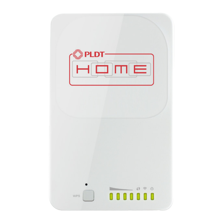
REPEATER
The wireless repeater extends the signal range
of many of PRO1’s wireless products. When
the W150W receives a coded wireless signal,
it repeats it to extend the wireless range of the
device.
®
Important Communication
Mode Note:
When using this product, any and all
components/devices of the system that
contain a selectable communication
mode (FSK/ASK Jumper Pin Switch),
MUST be set to ASK.

2
Getting to know the W150W Module
1
2LCD
Red Indicator Light
1
3
2
COMMUNICATION QUICK REFERENCE
When the W150W receives
a wireless signal to repeat, the
Recieved Symbol will ash.
After a few seconds the Red
Indicator Light and the
Transmit Symbol will ash.
Indicating a repeated signal.
3Module Button
Transmit symbol indicates
repeating signal.
Antenna symbol
indicates received
signal.
REFERENCE NUMBER indicates
the current repeater mode.
1. When powered, the set Device Reference Number appears on the LCD. To Determine the Device
Reference Number needed, see the chart below.
2. To enter Reference Number selection mode, press the Module Button . The Reference
Number will start ashing. While ashing, press Module Button again to select Reference Number
needed. Once desired number is selected--stop. The number will quit ashing in 5 seconds and the
Device Reference Number is set.
3
----
Reference
Number
1
2
3
4
4
4
Device the Signal
is coming from TO Device the Signal
is traveling to
----
Not used at this time
Indoor or Outdoor Remotes
(R251W, RZ251W, R250W, RZ250W) TOTO
TO
TO
TO
TO
Thermostat (T955WH)
Thermostat (Z955W)
Thermostat (Z955W)
Thermostat (T631W-2)
Wireless Thermostat
(T955WH, Z955W)
Equipment Base Module
Equipment Base Module
Damper Module (Z260W)
Equipment Base Module
3
1

3
INSTALLATION TIPS
Do not install the wireless module in locations:
• Where temperature could exceed 120ºF.
• Where exposed to rain or snow.
• Where exposed to extreme hot or cold.
NOTE: The wireless modules are NOT weatherproof.
Wireless Module - Installation
PRO1 Tip
Wireless Range
Range between the W150W module and the devices to be repeated is approximately 100 feet with no
obstructions and approximately 50 feet in standard residential construction. Place the W150W Repeater
somewhere between communicating devices to repeat the wireless signal and extend the range.
T955WH
W150W
BASE MODULE
Note:
The W150W Reference Number is
set to 3 in this example.
3

SUBBASE INSTALLATION & WIRING
For vertical mount put one screw top
and one screw bottom.
For horizontal mount put one screw left
and one screw right.
Mounting the wireless module subbase
4
The W150W must be hardwired (C and R terminals
connected to 24VAC power).
W150W Power Supply
C
R
C
L2
L1 (HOT)
R
Wiring Module to Power Supply
Horizontal mount
Horizontal mount
Vertical mount
UP
R
C
Vertical mount
Warning:
All components of the control
system and the thermostat
installation must conform to
Class II circuits per the NEC code.
Caution: Electrical Hazard
Failure to disconnect the power
before beginning to install this
product can cause electrical shock
or equipment damage.
Mount the Wireless Modules
Note:
The wireless modules can be wired
from the back or the bottom.
Align the 4 tabs on the subbase with
corresponding slots on the back of the
wireless modules. Then push gently
until the wireless repeater snaps in
place.

5
SPECIFICATIONS & CONTENT INFO
Power source
Operating ambient
Operating humidity
Frequency
Dimensions
18 to 30 VAC, NEC Class II, 50/60 Hz for hardwire (common wire)
+32ºF to +122ºF ( 0º to +50ºC )
90% non-condensing maximum
916 MHz
4.4 ”W x 4.4 ”H x .75”D
Specications
Pro1 IAQ Inc.
PO Box 3377
Springeld, MO 65804
Toll-free: 1-888-Pro1iaq (776-1427)
Toll Number (Outside the USA): 330-821-3600
Web: http://www.pro1iaq.com
Hours of Operation: Monday - Friday 9 AM - 6 PM Eastern
Warranty Registration:
Your new Pro1 wireless repeater has a 5 year limited warranty. You must register your warranty
within 60 days of installation. You can register your new product in 2 ways.
Go to www.pro1iaq.com, select warranty registration and ll out a short registration form.
- or -
Complete the form below and mail it to the address shown.
1
2
Complete form and mail to:
Name: ____________________________
Address: ____________________________
____________________________
City: ____________________________
State: ____________________________
Zip: _____________________
Thermostat Model: _____________________
Date Installed: _____________________
Pro1 IAQ Warranty Registration:
Pro1 IAQ Inc.
PO Box 3377
Springeld, MO 65804
