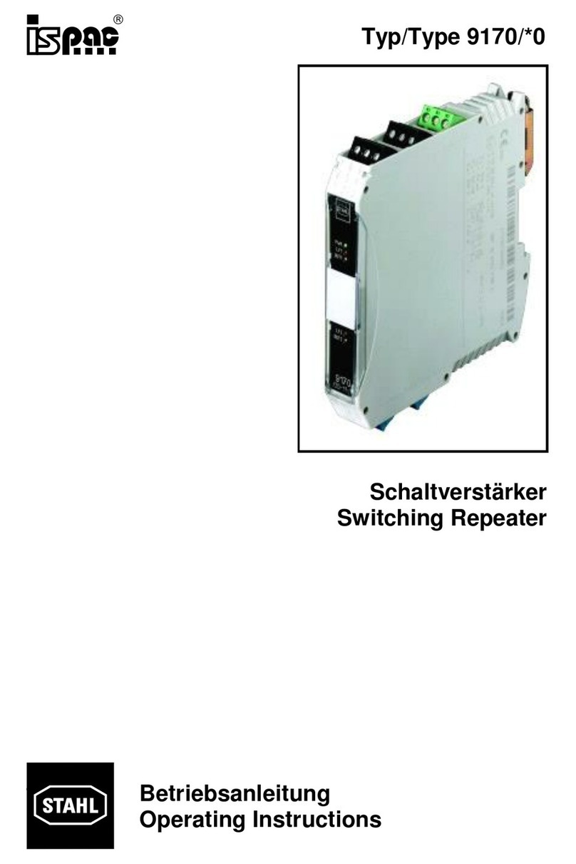
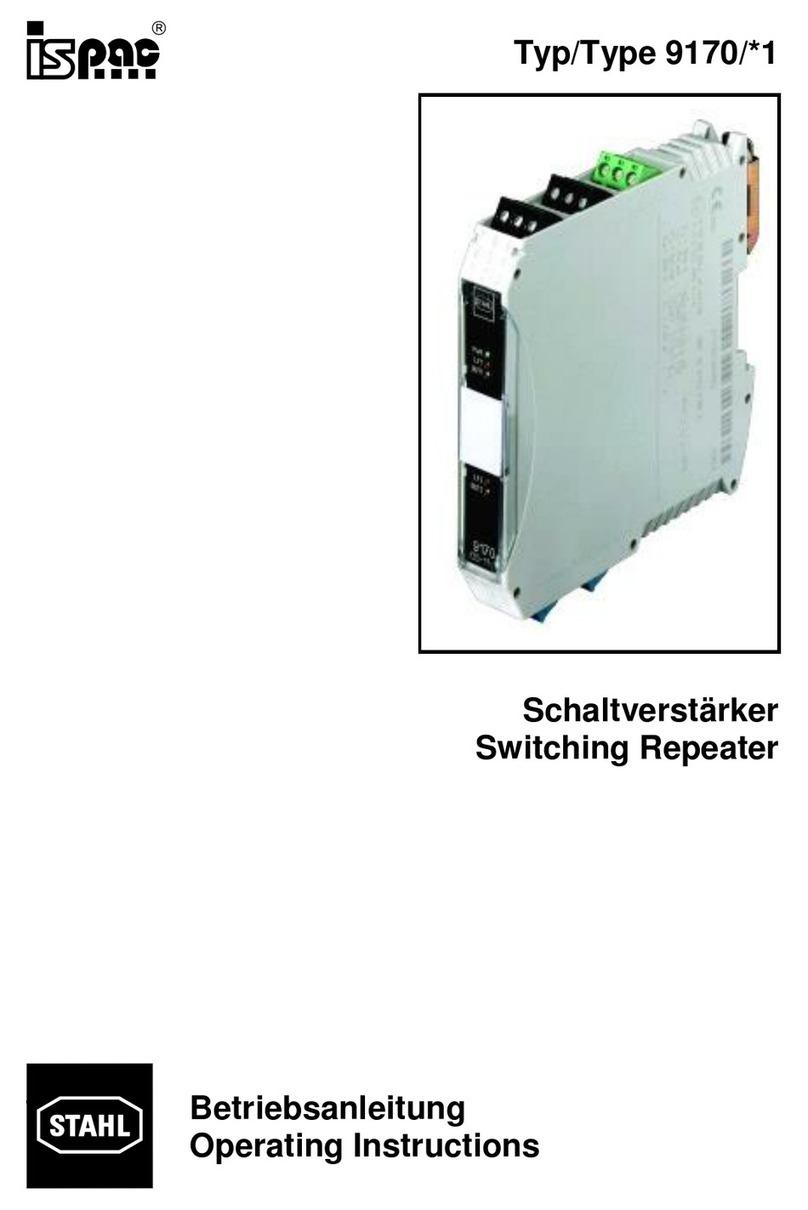
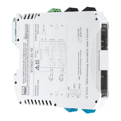
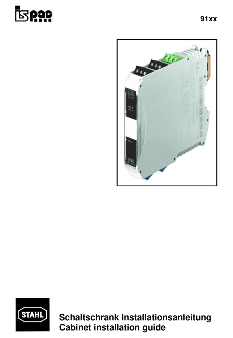
Stahl 9170/12-12-13 User manual

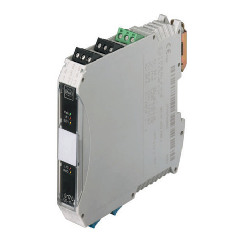
Type 9170
Switching Repeater
1.1.1
Operating Instructions
Type 9170
/*2
Switching Repeater

2
Content
1
Safety instructions....................................................................................................... 3
2
Conformity to standards.............................................................................................. 3
3
Function...................................................................................................................... 4
4
Marking and technical data .........................................................................................4
5
Engineering................................................................................................................. 5
5.1
Max. ambient temperatures.................................................................................. 5
5.2
Power dissipation................................................................................................. 5
5.3
Engineering of the power dissipation in cabinets..................................................6
6
Arrangement and fitting............................................................................................... 7
6.1
Dimensions.......................................................................................................... 7
6.2
Installation............................................................................................................ 7
6.3
Mounting and dismounting................................................................................... 7
7
Commissioning ........................................................................................................... 8
7.1
Connections......................................................................................................... 8
7.2
Engineering.......................................................................................................... 8
7.3
Settings................................................................................................................ 9
8
Operation and operational states ................................................................................ 9
9
Maintenance and repair ............................................................................................ 10
10
Accessories and spare parts.................................................................................. 10
EC-Declaration of Conformity........................................................................................... 11
EC-Type Examination Certificate ..................................................................................... 12

english Operating Instructions
Switching Repeater Type 9170/*2
3
1 Safety instructions
The most important safety instructions are summarised in this chapter. It is intended to
supplement the relevant regulations which must be studied by the personnel responsible.
When working in hazardous areas, the safety of personnel and plant depends on
complying with all relevant safety regulations. Assembly and maintenance staff working on
installations therefore have a particular responsibility. The precondition for this is an
accurate knowledge of the applicable regulations and provisions.
When installing and operating the device in an ATEX environment, the following has
to be observed:
•The national installation and assembly regulations (e.g. EN 60079-14) apply.
•The switching repeater is to be installed outside of hazardous areas.
•The switching repeater has to be connected to the Ground / Potential equalization via
the pac-Bus, terminal 2 by means of a wire with a diameter of # 16 AWG.
•The switching repeaters may only be connected to devices which will not be subjected
to voltages higher than AC 253 V (50 Hz).
•The safe maximum values of the connected field device(s) must correspond to the
values of the data sheet or the EC-type examination certificate.
•Interconnecting several active devices in an intrinsic safety circuit may result in other
safe maximum values. This could endanger the intrinsic safety!
•National safety and accident prevention regulations.
•Generally recognised technical regulations.
•Safety guidelines in these operating instructions.
•Any damage can compromise and even neutralise the explosion protection.
The following requirements apply if used in an MSHA environment:
•The switching repeater must be located out-by in a suitable enclosure or installed
inside an MSHA certified X/P enclosure if located in an area where permissible
equipment is required
•The installation shall preclude intermingling between the intrinsically safe input circuits
and the non-intrinsically safe power and relay circuits.
•The input power voltage to the switching repeater must not exceed a maximum 150
Vac rms or 31 Vdc.
•The voltage switched by the output relays must not exceed 150 Vac rms or 150 Vdc
and the current switched shall not exceed 4 Aac rms or 2 Adc.
•Pole 2 of the pac-Bus 5 pole terminal must be connected to frame ground.
•The output relays contacts of a two output channel switching repeater must switch
power from the same power source.
•Connection of a capacitive, inductive or voltage generating device to the intrinsically
safe input Channels 1 and 2 must be evaluated before being accepted as part of a
permissible machine.
Use the device in accordance with the regulations and for its intended purpose only (see
“Function”).
Incorrect or impermissible use or non-compliance with these instructions invalidates our
warranty provision.
No changes to the devices or components impairing their explosion protection are
permitted. Further, the device may only be fitted if it is undamaged, dry and clean.
2 Conformity to standards
The switching repeaters type 9170 comply with the following standards and directives:
Operating Instructions english
4
Switching Repeater Type 9170/*2
•EN 60947-5-6
•Directives 94/9/EG, 2004/108/EG
•IEC/EN 60079-0, EN 60079-11, EN 61241-11
•EN 61326-1
•ACRI 2001
3 Function
Switching repeaters are used for intrinsically safe operation of contacts, proximity switches
as defined by EN 60947-5-6 (NAMUR), optocoupler outputs, etc.Output variants equipped
with power relays have been provided to meet varying requirements.
4 Marking and technical data
Manufacturer
Type designation
CE marking
ATEX marking of explosion protection
and
and
Testing authority and certificate number
MSHA approval number
Max. ambient temperature range
R. STAHL
9170/*2-12-*3
C
0102
EII (1) G [Ex ia] IIC
EII (1) D [Ex ia] IIIC
EI (M1) [Ex ia] I
DMT 02 ATEX E 195 X
18-ISA090004-0
-4 °F...158 °F
(see chapter 5.1)
Safety data 1 channel 2 channels in parallel
Max. voltage U
o
Max. current I
o
Max. power P
o
Internal capacitance C
i
Internal inductance L
i
Max. connectable capacitance, C
o
IIC / IIB / I
Max. connectable inductance, L
o
IIC / IIB / I
Insulation voltage U
m
9,6 V 9,6 V
10 mA 20 mA
24 mW 48 mW
2,42 nF 4,84 nF
negligible negligible
3,6 µF/ 26 µF/ 99 µF 3,6 µF/ 26 µF/ 99 µF
350 mH / 1H / 1H 90 mH / 340 mH / 1H
253 V 253 V
See EC-type examination certificate for further information and value combinations.
Technical data (excerpted from the
data sheet)
Power supply
Nominal voltage U
N
DC power supply (Types 9170/*2-**-13)
AC power supply (Types 9170/*2-**-23)
24 V DC
120 V AC
Nominal current (for U
N
) DC/AC power
supply 50 mA / 13 mA
Power consumption (for U
N
) 0,9 W / 2 VA
I.S. Input in acc. with EN 60947-5-6
Output (see Operation and operational
states)
Power relay
max. 150 V AC / 4 A; 150 V DC / 2 A
Ambient conditions
Max. operating temperature -4 ...158 °F
Storage temperature -40...176 °F
Relative humidity (no condensation) < 95 %
Additional technical data can be found in the current data sheet.
Please consult with the manufacturer before operating under conditions which deviate from
the standard operating conditions.

english Operating Instructions
Switching Repeater Type 9170/*2
5
5 Engineering
5.1 Max. ambient temperatures
The ISpac isolators can be used over a wide temperature range. Depending on the isolator
version and installation method different maximum ambient temperatures may result.
Ventilation:
Without ventilation
Installation:
Single unit
DIN
-
rail
Orientation:
any
vertical
horizontal
Channels
Type
:
1
9170/12
-
12
-
13
158 °F
149 °
F
149 °
F
9170/12
-
12
-
23
149 °
F
158 °
F
2
9170/22
-
12
-
13
158 °F
131 °
F
149 °
F
9170/22
-
12
-
23
131 °
F
149 °
F
Ventilation:
With ventilation
Installation:
Single unit
DIN
-
rail
Or
ientation:
any
vertical
horizontal
Channels
Type:
1
9170/12
-
12
-
13
158 °F
158 °
F
158 °
F
9170/12
-
12
-
23
158 °
F
158 °
F
2
9170/22
-
12
-
13
158 °F
149 °
F
149 °
F
9170/22
-
12
-
23
149 °
F
149 °
F
5.2 Power dissipation
Data sheets are describing the maximum power dissipation in standard operation. In
practice not all isolators are working with full load. Therefore engineering is done typically
with an average power dissipation of 70 % (P
70%
).
Type
Channels
max. power dissipation
70 % power dissipation
9170/12-12-13 1 0,7 W 0,5 W
9170/22-12-13 2 1,2 W 0,8 W
9170/12-12-23 1 1,0 W 0,7 W
9170/22-12-23 2 1,6 W 1,1 W

Operating Instructions english
6
Switching Repeater Type 9170/*2
5.3 Engineering of the power dissipation in cabinets
When electronic devices are integrated in cabinets free air movement is restricted and the
temperature rises. To minimise the temperature rise it is important to optimise the power
dissipation as well as the elimination of the produced heat inside a cabinet.
a) Natural Convection in closed cabinets
•Application: when the dissipated power is moderate and when the system operates in a
dusty or harsh environment
•Calculation of the maximum allowed power dissipation:
Pmax = ∆
∆∆
∆t * S * K
P
max
[W] max. allowed power dissipation in the cabinet
∆
t [°C] max. allowed temperature rise
S [m²] free, heat emitting surface of the cabinet
K [(W/m²*°C)] thermal emitting coefficient (K=5.5 for painted steel sheets)
The calculated value for P
max
has to be smaller than the total average power dissipation
(70 % of max. power dissipation) of the installed isolators: Pmax < ∑P
70%
b) Natural convection in open cabinets
•Function: the heat is removed by cool air flowing through the devices
•Requirements:
- inlet and outlet ports in the lower and upper ends of the cabinet
- the air flow path must be kept free from obstacles.
•Result: Depending on the engineering the improvement can reach a two times higher
power dissipation as with a)
c) Forced ventilation with heat exchanger in closed cabinets
•Application: when either the harsh environment or the high dissipated power do not
allow natural convection
•Function: a heat exchanger with a fan pulls the air into the cabinet and pushes it into the
heat exchanger plates that are cooled by the external ambient air moved by a second
fan.
•Result: Depending on the engineering the improvement can reach a 5 or 6 times
higher power dissipation as with a)
d) Forced ventilation in open cabinets
•Function: the filtered air is taken from the bottom cabinet openings by one or more fans,
flows through the devices, and finally exits at the top of the cabinet.
•Calculation of the required air flow:
Q = (3.1 * P
70%
) / ∆
∆∆
∆t
Q [m³/h] required air flow
P
70%
[W] dissipated power (70 % of max. power dissipation)
∆
t [°C] allowed temperature rise in the cabinet
e) Air conditioned cabinets
•Application: for hot climates - it is possible to reach a cabinet temperature equal or even
lower than the ambient temperature
•Function: a specific refrigerating system or the existing air conditioning system can be
used for cabinet conditioning

english
Operating Instructions
Switching Repeater Type 9170/*2
6 Arrangement and fitting
6.1 Dimensions
6.2 Installation
The switching repeater is to be installed outside of hazardous areas.
6.3 Mounting and dismounting
a) Detachable terminals
All devices are provided with detachable terminals. A screwdriver is needed to
remove the terminals (as shown in the picture).
b) Mounting on DIN rails fitted with a pac-Bus
As depicted in the photo, set the device in position on the pac-
Bus (already
mounted on the DIN rail) and tilt/snap until it locks in.
Do not tilt at an angle to either side when snapping onto the pac-Bus.
Note: In order to prevent pole reversal during installation, the pac-
Bus elements
have been equipped with a keyed connection plug (see photo). The module is
fitted with a matching slot.
c) Connection of ground
The connection of ground to the switching
repeater is mandatory in order to achieve proper
explosion protection.
Please mount the terminal set 9194/50-01 as
illustrated in picture on the right side. Please
connect a ground connection of # 16 AWG to
terminal 2 of the terminal set.
Screw terminals
Operating Instructions
Switching Repeater Type 9170/*2
7
All devices are provided with detachable terminals. A screwdriver is needed to
Bus (already
Bus elements
have been equipped with a keyed connection plug (see photo). The module is
Dimension X
Screw terminals
108 mm

Operating Instructions english
8
Switching Repeater Type 9170/*2
7 Commissioning
7.1 Connections
Types 9170/*2-12-13
(24 V DC power supply)
Types 9170/*2-12-23
(120 V AC power supply)
7.2 Engineering
a) Mode of connection for line fault identification (volt-free contacts
at the input)
Open circuit identification: 22 kΩ(or 33 kΩ) in parallel
Short circuit identification: 2.7 kΩin series
The loading has to carry out in direct proximity of the contact.
b) Mode of connection for inductive loading at the output:
Inductive loadings have to be connected with a free
wheel diode.
We do not recommend to use a loading via varistor.
+
-
Hazardous location
Safe area
2.7
k
k
Ω
22 k
Ω
L-
L+

english Operating Instructions
Switching Repeater Type 9170/*2
9
7.3 Settings
Line fault detection (LF)
Line of action inverted (INV)
deactivated *)
activated
OFF *)
ON
Channel 1
Channel 2
*) Default factory setting
8 Operation and operational states
Output state
for “line of action inverted” (see 7.3)
Input Input current OFF ON
Line fault detection LF = deactivated
Proximity switch high
impedance / Contact:
open / open circuit I
E
≤1.2 mA Relay not energized /
Electronic output
deactivated
Relay energized /
Electronic output activated
Proximity switch low
impedance / Contact:
closed / short circuit I
E
≥2.1 mA Relay energized /
Electronic output activated
Relay not energized /
Electronic output
deactivated
Line fault detection LF = activated
Open circuit I
E
≤0.05...0.35mA Relay not energized /
Electronic output
deactivated
Relay not energized /
Electronic output
deactivated
Proximity switch high
impedance / Contact:
open I
E
= 0.35…1.2 mA Relay not energized /
Electronic output
deactivated
Relay energized /
Electronic output activated
Proximity switch low
impedance / Contact:
closed I
E
= 2.1…5 mA Relay energized /
Electronic output activated
Relay not energized /
Electronic output
deactivated
Short circuit R
E
≥100..360 ΩRelay not energized /
Electronic output
deactivated
Relay not energized /
Electronic output
deactivated
LF1
LF2
INV1
INV2
ON
OFF
1
2
LF1
LF2
INV1
INV2
ON
OFF
1
2
LF1
LF2
INV1
INV2
ON
OFF
1
2
LF1
LF2
INV1
INV2
ON
OFF
1
2

Operating Instructions english
10
Switching Repeater Type 9170/*2
9 Maintenance and repair
It is recommended that all repairs to our devices be carried out by R. STAHL.
In exceptional cases, repair may be performed by approved third-parties.
The devices are maintenance-free.
Troubleshooting chart:
Error detection Malfunction cause(s) Corrective action
“PWR” LED does not lit Power supply failure
Device fuse is defective
Polarity reversal
Check power supply.
If device fuse is defective, send device in for
repair.
Connect the power acc. to operating guide
“LF” LED lights all the time Switching element is not connected
correctly – short circuit or disruption
Switching element does not work in
compliance with NAMUR
Please verify that the connection is established
correctly.
Please apply the mode of connection for volt-
free contacts as described in 7.2 .
LED “OUT” lights but the
state of operation at the
output does not change
The exchangeable terminals are
mixed up. Please connect the terminals to the predefined
socket.
High switching frequencies
are not transmitted The electronic output is optimized for
the application along with active I/O
cards. In case of passive I/O cards
the potential for the generation of
High Level is missing.
The High Level can be generated if an resistor
is connected externally to the supply voltage
(e.g. +5V).
Self test
In order to check basic functions of the device, you may apply the following test steps.
Please disconnect the exchangeable terminals first. (see 6.3)
•Connect the device to the power supply (directly via terminals 7 and 9)
•Deactivate the line fault detection my means of the DIP switches at the front of
the device.
•Establish an electrical connection between terminal 11 and 12 (in case of dual
channel devices additionally between terminal 14 and 15)
•The LED ”OUT” (yellow) lights up. It indicates that the output has switched. If you
disconnect the connection between the terminals the LED turns dark. The result
of this test indicates that input signals are processed.
•Activate the line fault detection. The LED “LF” lights up no matter if the
connection between the terminal is established or not.
If the procedure described above does not obtain the desired result, please contact your
local R.STAHL sales and service representative. In order to quickly process your request,
please provide us with the following information:
•Type and serial number
•Purchase date
•Description of malfunction
•Application description (particularly the configuration of the input/output circuitry)
10 Accessories and spare parts
Use only original spare parts from R. STAHL Schaltgeräte GmbH.

11
EC-Declaration of Conformity

12
EC-Type Examination Certificate


R. STAHL Schaltgeräte GmbH
Am Bahnhof 30
74638 Waldenburg (Württ.) – Germany
www.stahl.de
ID-Nr. 9170611310
S-BA-9170/.2-001-en-
06/2009
This manual suits for next models
3
Table of contents
Other Stahl Repeater manuals

Stahl
Stahl ispac 9170/0 Series User manual

Stahl
Stahl 9186 Series User manual

Stahl
Stahl 9185/11-35-10 User manual

Stahl
Stahl 9163 Series User manual

Stahl
Stahl 9185 Series User manual

Stahl
Stahl 9164/13-20-0 Series User manual

Stahl
Stahl Ispac 9170 1 Series User manual

Stahl
Stahl ISpac 91 Series User manual

Stahl
Stahl 9186 5-12-11 Series User manual

Stahl
Stahl ispac 9186/12 User manual