pro bel Freeway 64 User manual

r
ro
o-
-B
Be
el
l
L
Lt
td
d
F
Fr
re
ee
ew
wa
ay
y
6
64
4
a
an
na
al
lo
og
gu
ue
e
v
vi
id
de
eo
o
U
U-
-F
Fr
re
ee
ew
wa
ay
y
6
64
4
A
An
na
al
lo
og
gu
ue
e
V
Vi
id
de
eo
o
1
1
C
Co
on
nt
te
en
nt
ts
s
1
1
I
In
nt
tr
ro
od
du
uc
ct
ti
io
on
n
2
2
2
2
I
In
ns
st
ta
al
ll
la
at
ti
io
on
n
a
an
nd
d
c
co
on
nf
fi
ig
gu
ur
ra
at
ti
io
on
n
4
4
2.1 Removal and replacement of module 4
2.2 Expanding from 16x16 to 64x64 6
2.3 Setting the level switch 8
2.4 Setting the destination assign switch 10
2.5 Selecting DC couple/DC restore 10
2.6 Output cable equalisation 12
2.7 LED indications 13
2.8 Resetting the module 14
3
3
T
Th
he
eo
or
ry
y
o
of
f
o
op
pe
er
ra
at
ti
io
on
n
1
16
6
4
4
r
ro
ob
bl
le
em
m
s
so
ol
lv
vi
in
ng
g
1
18
8
5
5
S
Sp
pe
ec
ci
if
fi
ic
ca
at
ti
io
on
n
2
20
0

F
Fr
re
ee
ew
wa
ay
y
6
64
4
a
an
na
al
lo
og
gu
ue
e
v
vi
id
de
eo
o
r
ro
o-
-B
Be
el
l
L
Lt
td
d
2
2
U
U-
-F
Fr
re
ee
ew
wa
ay
y
6
64
4
A
An
na
al
lo
og
gu
ue
e
V
Vi
id
de
eo
o
1
1
I
In
nt
tr
ro
od
du
uc
ct
ti
io
on
n
his manual covers the installation, operation and operational alignment of the
analogue video routing card (3740) for the reeway series of routing switchers.
n
n
A
An
na
al
lo
og
gu
ue
e
v
vi
id
de
eo
o
r
ro
ou
ut
ti
in
ng
g
Any demanding television applications will benefit from the inherent wide
bandwidth and high slew-rate capacity of this router. he circuitry offers complete
transparency to all encoded vertical-interval data and is fully compatible with SIS
signals.
he main features are:
· 30MHz bandwidth
· dual standard vertical-interval switching
· DC coupled or DC restored operation
· composite and YUV/RGB(S) configurations

r
ro
o-
-B
Be
el
l
L
Lt
td
d
T
Te
ec
ch
hn
ni
ic
ca
al
l
m
ma
an
nu
ua
al
l
U
U-
-F
Fr
re
ee
ew
wa
ay
y
6
64
4
A
An
na
al
lo
og
gu
ue
e
V
Vi
id
de
eo
o
3
3
1-16 analogue
video inputs
1 - 16 analogue
video outputs
reeway
B
Bl
lo
oc
ck
k
d
di
ia
ag
gr
ra
am
m

F
Fr
re
ee
ew
wa
ay
y
6
64
4
a
an
na
al
lo
og
gu
ue
e
v
vi
id
de
eo
o
r
ro
o-
-B
Be
el
l
L
Lt
td
d
4
4
U
U-
-F
Fr
re
ee
ew
wa
ay
y
6
64
4
A
An
na
al
lo
og
gu
ue
e
V
Vi
id
de
eo
o
2
2
I
In
ns
st
ta
al
ll
la
at
ti
io
on
n
a
an
nd
d
c
co
on
nf
fi
ig
gu
ur
ra
at
ti
io
on
n
n
n
2
2.
.1
1
R
Re
em
mo
ov
va
al
l
a
an
nd
d
r
re
ep
pl
la
ac
ce
em
me
en
nt
t
o
of
f
m
mo
od
du
ul
le
e
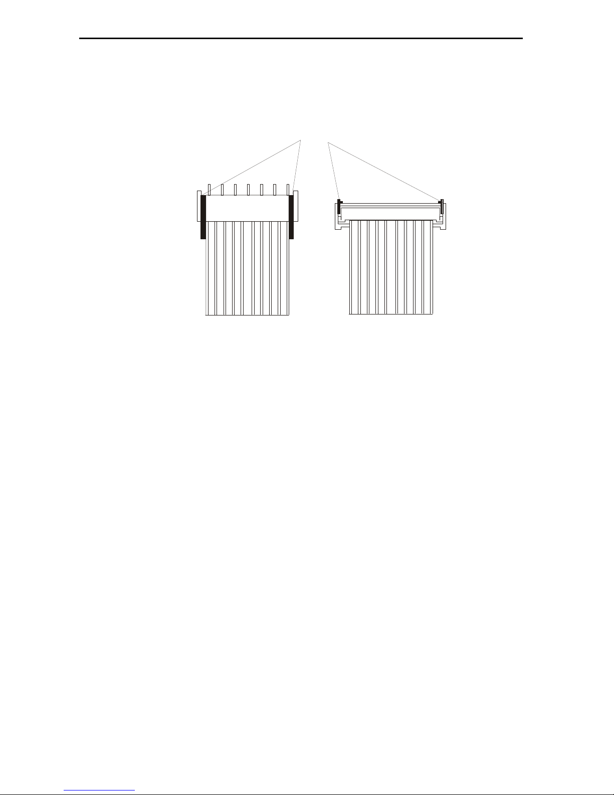
he module can be removed and replaced from the frame, powered or un-powered,
using the following procedure. When removing the bottom card it is necessary to
remove the door before continuing. For removal purposes it is advisable to remove
the ribbon cables first and then the cards.
· release the ribbon cables by pushing the catches up on either end of the
connector as shown
· lift up the card ejector on the module and gently pull the card out
Replacement is the reverse of above:
· slide the card along the guide rail of the required slot, gently pushing it fully
home until it marries up with the connector on the motherboard
r
ro
o-
-B
Be
el
l
L
Lt
td
d
T
Te
ec
ch
hn
ni
ic
ca
al
l
m
ma
an
nu
ua
al
l
U
U-
-F
Fr
re
ee
ew
wa
ay
y
6
64
4
A
An
na
al
lo
og
gu
ue
e
V
Vi
id
de
eo
o
5
5
Catches
Top view
Front view
F
Fr
re
ee
ew
wa
ay
y
6
64
4
a
an
na
al
lo
og
gu
ue
e
v
vi
id
de
eo
o
r
ro
o-
-B
Be
el
l
L
Lt
td
d
6
6
U
U-
-F
Fr
re
ee
ew
wa
ay
y
6
64
4
A
An
na
al
lo
og
gu
ue
e
V
Vi
id
de
eo
o
n
n
2
2.
.2
2
E
Ex
xp
pa
an
nd
di
in
ng
g
f
fr
ro
om
m
1
16
6x
x1
16
6
t
to
o
6
64
4x
x6
64
4
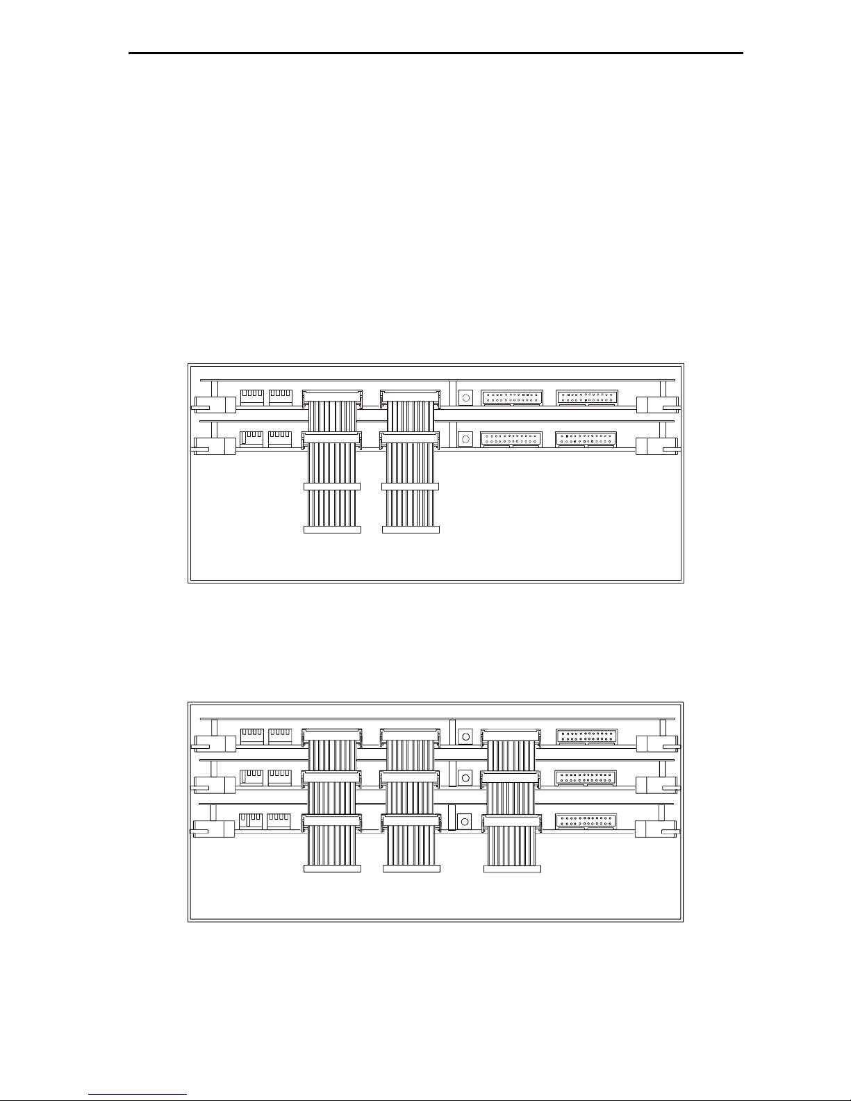
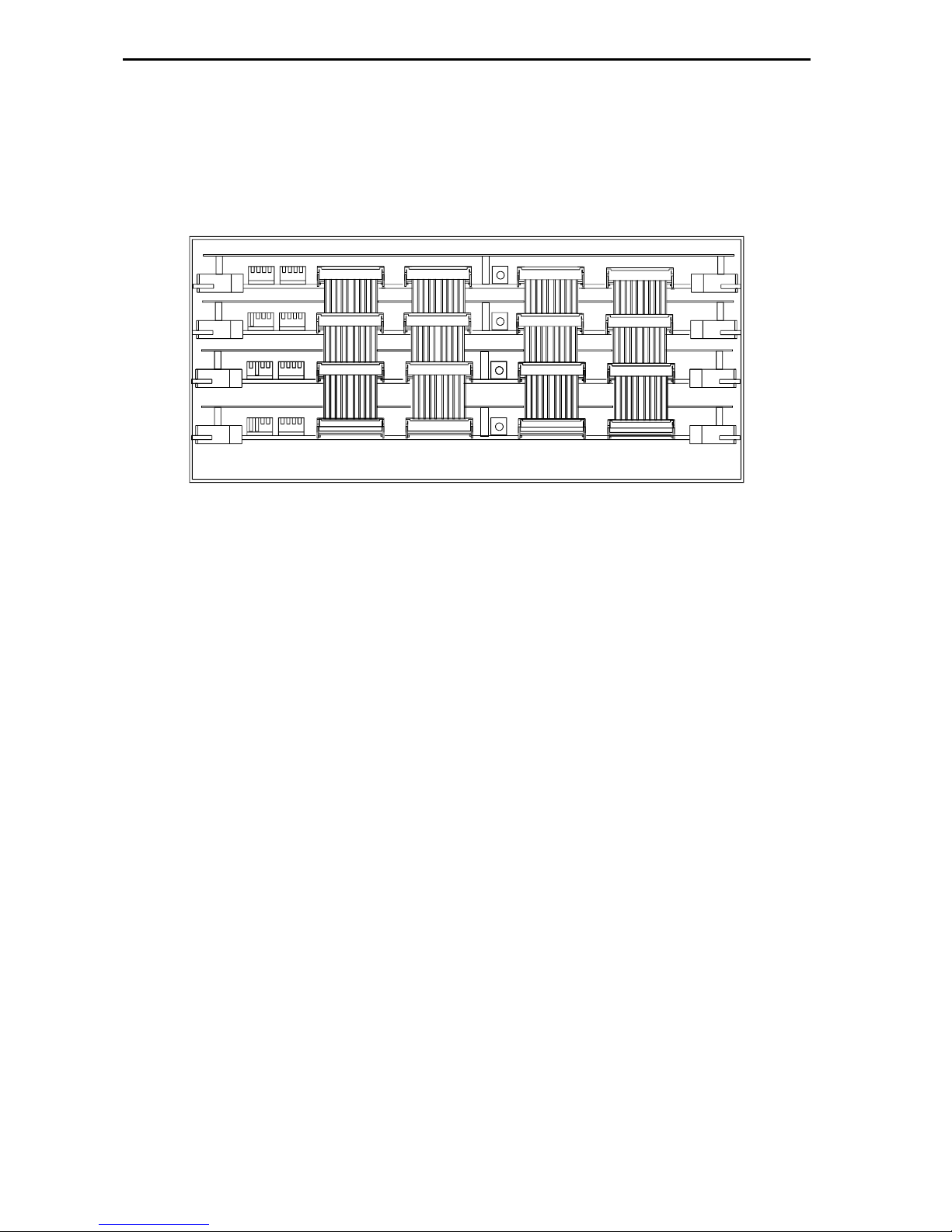
he following diagrams show the cable connections required for expanding the
router from 16x16.
3
3
2
2
x
x
3
3
2
2
e
e
x
x
p
p
a
a
n
n
s
s
i
i
o
o
n
n
4
48
8x
x4
48
8
e
ex
xp
pa
an
ns
si
io
on
n
r
ro
o-
-B
Be
el
l
L
Lt
td
d
T
Te
ec
ch
hn
ni
ic
ca
al
l
m
ma
an
nu
ua
al
l
U
U-
-F
Fr
re
ee
ew
wa
ay
y
6
64
4
A
An
na
al
lo
og
gu
ue
e
V
Vi
id
de
eo
o
7
7
6
6
4
4
x
x
6
6
4
4
e
e
x
x
p
p
a
a
n
n
s
s
i
i
o
o
n
n

F
Fr
re
ee
ew
wa
ay
y
6
64
4
a
an
na
al
lo
og
gu
ue
e
v
vi
id
de
eo
o
r
ro
o-
-B
Be
el
l
L
Lt
td
d
8
8
U
U-
-F
Fr
re
ee
ew
wa
ay
y
6
64
4
A
An
na
al
lo
og
gu
ue
e
V
Vi
id
de
eo
o
n
n
2
2.
.3
3
S
Se
et
tt
ti
in
ng
g
t
th
he
e
l
le
ev
ve
el
l
s
sw
wi
it
tc
ch
h
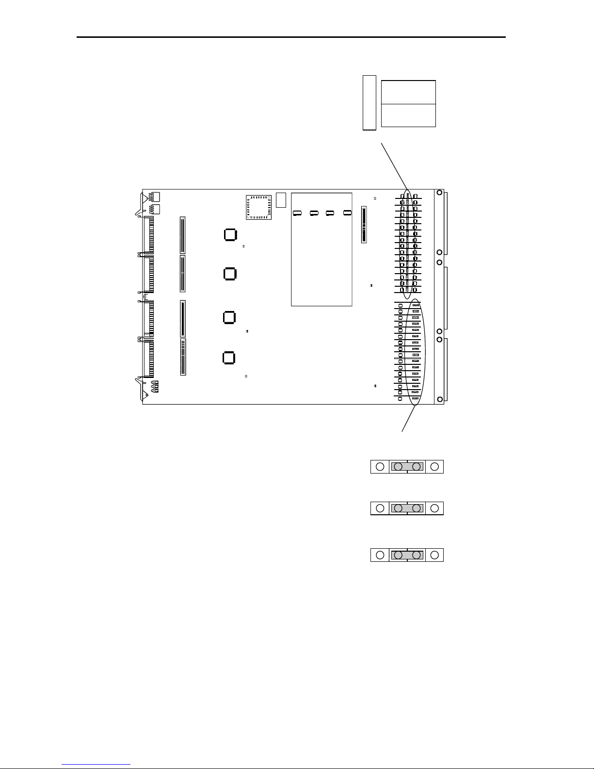
he card edge controls and indicators on the router card are limited to the Level and
Higher Destination Decode switches and the standard 3 LED array, both of which are
described in part one of the reeway Series User guide.
For separate routers to be controlled independently, each must have a different level
address set. his operation is achieved by means of the DIL switch marked level on
the front of each reeway card.
he levels are set thus:
W 1 W 2 W 3 W 4 Level No
0 0 0 0 1
1 0 0 0 2
0 1 0 0 3
1 1 0 0 4
0 0 1 0 5
1 0 1 0 6
0 1 1 0 7
1 1 1 0 8
he maximum total number of independent levels is 8. A typical system might be
arranged like this:
Level 1 Serial Digital Video
Level 2 Analogue Video
Level 3 AES Digital Audio
Level 4 Stereo Analogue Audio

r
ro
o-
-B
Be
el
l
L
Lt
td
d
T
Te
ec
ch
hn
ni
ic
ca
al
l
m
ma
an
nu
ua
al
l
U
U-
-F
Fr
re
ee
ew
wa
ay
y
6
64
4
A
An
na
al
lo
og
gu
ue
e
V
Vi
id
de
eo
o
9
9
Control card
Reset
switch
Off On
1
4
1
0
Off On
1
4
1
0
Dest
SW1
SW2
Level
ello
+5V
-5V
Green
LEDs

F
Fr
re
ee
ew
wa
ay
y
6
64
4
a
an
na
al
lo
og
gu
ue
e
v
vi
id
de
eo
o
r
ro
o-
-B
Be
el
l
L
Lt
td
d
1
10
0
U
U-
-F
Fr
re
ee
ew
wa
ay
y
6
64
4
A
An
na
al
lo
og
gu
ue
e
V
Vi
id
de
eo
o
n
n
2
2.
.4
4
S
Se
et
tt
ti
in
ng
g
t
th
he
e
d
de
es
st
ti
in
na
at
ti
io
on
n
a
as
ss
si
ig
gn
n
s
sw
wi
it
tc
ch
h
What’s the purpose of the switch marked ‘HIGHER DES DECODE’? Well, because we
make all reeway modules the same, in a router bigger than 16x16, you have to ‘tell’
each card what range of sources and destinations it’s assigned to. hat’s the purpose
of this switch. he range is assigned thus:
W 1 W 2 W 3 W 4 ource and destination Range
0 0 x x 1-16
1 0 x x 17-32
0 1 x x 33-48
1 1 x x 49-64
n
n
2
2.
.5
5
S
Se
el
le
ec
ct
ti
in
ng
g
D
DC
C
c
co
ou
up
pl
le
e/
/D
DC
C
r
re
es
st
to
or
re
e
In traditional television applications a DC restore function is nearly always
appropriate - in order to remove DC sit variations between signals. Without this
function, switching between signals with different C components can cause frame-
roll due to corruption of sync field-block.
However, in other applications of a wideband analogue router, the DC restore
function is definitely not appropriate. hese include the routing of computer-type
RGB graphics signals and medium rate telecoms signals. In these cases a stable DC
path is required.
o cater for all circumstances, reeway provides a user selection of a DC restored
input signal stage, or a DC coupled input stage ( all circuitry downstream is DC
coupled). his is selectable by means of PL9 which may be found in each signal block.
DC COUPLE selection
DC RESTORE selection
DC COUPLE
DC REST
DC COUPLE
DC REST
r
ro
o-
-B
Be
el
l
L
Lt
td
d
T
Te
ec
ch
hn
ni
ic
ca
al
l
m
ma
an
nu
ua
al
l
U
U-
-F
Fr
re
ee
ew
wa
ay
y
6
64
4
A
An
na
al
lo
og
gu
ue
e
V
Vi
id
de
eo
o
1
11
1
DC COUPLE
DC REST
PL9
Output equalisation
0m
10m
20m
F
Fr
re
ee
ew
wa
ay
y
6
64
4
a
an
na
al
lo
og
gu
ue
e
v
vi
id
de
eo
o
r
ro
o-
-B
Be
el
l
L
Lt
td
d
1
12
2
U
U-
-F
Fr
re
ee
ew
wa
ay
y
6
64
4
A
An
na
al
lo
og
gu
ue
e
V
Vi
id
de
eo
o
n
n
2
2.
.6
6
O
Ou
ut
tp
pu
ut
t
c
ca
ab
bl
le
e
e
eq
qu
ua
al
li
is
sa
at
ti
io
on
n
Output cable equalisation is useful in order to maintain frequency response in
situations wher the equipment ‘following’ the router is not immediately adjacent to
the router frame. Even 10 metres of good quality video cable can cause appreciable
attenuation of colour information in a composite signal. For this reason reeway
includes selectable output cable equalisation. his is not continuously variable, but is
selectable (on an input by output basis) in three regimes: 0 metres, 10 metres and 20
metres.
Provides PSF1/2, Belden 8281 or equivalent cable is used, these three settings can
compensate for cable losses for cables up to 25 metres in length, ensuring response
at subcarrier frequency never exceeds ±1% (±0.1dB).
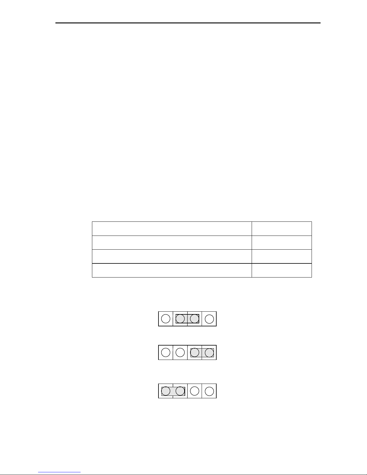
he table below notates the appropriate positions for output equalisation links for
given cable lengths.
Cable length Link position
PSF 1/2 between 0 and 5 metres 0m
PSF 1/2 greater than 5 metres, but less than 15 metres 10m
PSF 1/2 greater than 15 metres, but less than 25 metres 20m
Link positions are shown below:
0m
10m
20m

r
ro
o-
-B
Be
el
l
L
Lt
td
d
T
Te
ec
ch
hn
ni
ic
ca
al
l
m
ma
an
nu
ua
al
l
U
U-
-F
Fr
re
ee
ew
wa
ay
y
6
64
4
A
An
na
al
lo
og
gu
ue
e
V
Vi
id
de
eo
o
1
13
3
n
n
2
2.
.7
7
L
LE
ED
D
i
in
nd
di
ic
ca
at
ti
io
on
ns
s
wo of the three LEDs simply indicate that power is arriving at the board. reeway
routers all operate from two rails only (where others are needed these are generated
on the reeway cards themselves). he two rails are +5V and -5V.
he third LED is labelled ‘HELLO’. his is useful in determining if the control system
has spoken to a particular board and, specifically, to tell you if you set the ‘level’ and
‘higher dest decode’ switches correctly.
When the control system sends a command (say in response to a button push), the
appropriate part of the router responds, depending on how the board configuration
switches are set.
If a board receives a command on which it should act, it ‘winks’ the ‘HELLO’ LED.
Meaning, ‘Hello, I’ve just received a command that’s relevant according to my
programmed place in the scheme of things.’

F
Fr
re
ee
ew
wa
ay
y
6
64
4
a
an
na
al
lo
og
gu
ue
e
v
vi
id
de
eo
o
r
ro
o-
-B
Be
el
l
L
Lt
td
d
1
14
4
U
U-
-F
Fr
re
ee
ew
wa
ay
y
6
64
4
A
An
na
al
lo
og
gu
ue
e
V
Vi
id
de
eo
o
n
n
2
2.
.8
8
R
Re
es
se
et
tt
ti
in
ng
g
t
th
he
e
m
mo
od
du
ul
le
e
here are physically two RESE switches available to perform a hard reset of the
Freeway controller. One is located on the edge of the 2440 sub-module and the other
is remotely located on the front edge of the video card on which the 2440 is sited.
Pressing either has the same effect.
Initiating a hard reset is akin to powering down and powering up the control frame.
he controller re-boots and follows the usual power-up sequence. It should be noted
that the panels will shut down and then be restored after initialisation has
completed. It should also be noted that resetting the active controller in a dual
control environment will cause system changeover.
If no changes have been made to the database then no crosspoints will be changed.
However, crosspoint settings may change if the level type for a level was changed
prior to the reset as during initialisation the crosspoints are set according to the level
type for that level.
It is also advisable to perform a reset after database parameters are changed as
certain changes only take effect after a reset, i.e. changing level type, panel type,
source overrides, and controllable destinations.

r
ro
o-
-B
Be
el
l
L
Lt
td
d
T
Te
ec
ch
hn
ni
ic
ca
al
l
m
ma
an
nu
ua
al
l
U
U-
-F
Fr
re
ee
ew
wa
ay
y
6
64
4
A
An
na
al
lo
og
gu
ue
e
V
Vi
id
de
eo
o
1
15
5

F
Fr
re
ee
ew
wa
ay
y
6
64
4
a
an
na
al
lo
og
gu
ue
e
v
vi
id
de
eo
o
r
ro
o-
-B
Be
el
l
L
Lt
td
d
1
16
6
U
U-
-F
Fr
re
ee
ew
wa
ay
y
6
64
4
A
An
na
al
lo
og
gu
ue
e
V
Vi
id
de
eo
o
3
3
T
Th
he
eo
or
ry
y
o
of
f
o
op
pe
er
ra
at
ti
io
on
n
he 16 inputs are buffered using DC couple/DC restore circuitry and then routed by
the 64x16 crosspoint array. he microprocessor sets control destination and source
addresses and provides the strobes to the crosspoint array to set the routes.
he output amplifiers have three selectable eq/gain regimes which are selectable
with a moveable link.

r
ro
o-
-B
Be
el
l
L
Lt
td
d
T
Te
ec
ch
hn
ni
ic
ca
al
l
m
ma
an
nu
ua
al
l
U
U-
-F
Fr
re
ee
ew
wa
ay
y
6
64
4
A
An
na
al
lo
og
gu
ue
e
V
Vi
id
de
eo
o
1
17
7

F
Fr
re
ee
ew
wa
ay
y
6
64
4
a
an
na
al
lo
og
gu
ue
e
v
vi
id
de
eo
o
r
ro
o-
-B
Be
el
l
L
Lt
td
d
1
18
8
U
U-
-F
Fr
re
ee
ew
wa
ay
y
6
64
4
A
An
na
al
lo
og
gu
ue
e
V
Vi
id
de
eo
o
4
4
P
Pr
ro
ob
bl
le
em
m
s
so
ol
lv
vi
in
ng
g
T
Th
he
e
g
gr
re
ee
en
n
L
LE
ED
Ds
s
o
on
n
t
th
he
e
r
ro
ou
ut
ti
in
ng
g
c
ca
ar
rd
d
a
ar
re
e
o
of
ff
f?
?
here is no power on the card.
· check that there is power from the PSUs
· check cable interconnections
· ensure that the card is properly seated in the frame
T
Th
he
e
H
HE
EL
LL
LO
O
L
LE
ED
D
o
on
n
t
th
he
e
c
ca
ar
rd
d
r
re
em
ma
ai
in
ns
s
o
of
ff
f?
?
No command has been received by the board.
· check the power
· check that the ‘level’ and ‘higher dest decode’ switches are set correctly
· check cable interconnections

r
ro
o-
-B
Be
el
l
L
Lt
td
d
T
Te
ec
ch
hn
ni
ic
ca
al
l
m
ma
an
nu
ua
al
l
U
U-
-F
Fr
re
ee
ew
wa
ay
y
6
64
4
A
An
na
al
lo
og
gu
ue
e
V
Vi
id
de
eo
o
1
19
9

F
Fr
re
ee
ew
wa
ay
y
6
64
4
a
an
na
al
lo
og
gu
ue
e
v
vi
id
de
eo
o
r
ro
o-
-B
Be
el
l
L
Lt
td
d
2
20
0
U
U-
-F
Fr
re
ee
ew
wa
ay
y
6
64
4
A
An
na
al
lo
og
gu
ue
e
V
Vi
id
de
eo
o
5
5
S
Sp
pe
ec
ci
if
fi
ic
ca
at
ti
io
on
n
n
n
I
In
np
pu
ut
ts
s
Number and type: 16: unbalanced on BNCs, 1V pk-pk amplitude
Impedance: 75W
Return loss: Better than 40dB to 3.58MHz and 4.43MHz
Superimposed DC: ±
1V max
Coupling: DC or sync-tip restored
n
n
O
Ou
ut
tp
pu
ut
ts
s
Number and type: 16 unbalanced on BNCs
Impedance: 75W
Return loss: Better than 40dB to 3.58MHz and 4.43MHz
DC offset: Less than 50mV
n
n
P
Pe
er
rf
fo
or
rm
ma
an
nc
ce
e
Gain: 0dB ±0.1dB
Freq. Response: ±
0.1dB to 8MHz,+2/-3dB to 30MHz
Crosstalk } -63dB (single adjacent)
} -60dB (all hostile) @ 4.43MHz
Output eq.: Selectable cable eq. on outputs
2 Pulse/Bar: <0.2% K
Chrom/Lum gain: <
±
0.5%
Chrom/Lum delay: <
±
2ns
Group Delay Var: <5ns 50Hz to 15MHz
Differential Phase: <0.15° @ 4.43MHz
Table of contents


