Pro-face CA1-WMALRG-01 User manual

-1-
Thank you for purchasing Pro-Face's Wall Mount Adaptor.
This adaptor can be attached to the following products:
PS-600G Series, PS-500P Series, GP-2500/2600 Series, FP-2500/2600 Series,
GLC2600 Series, and GP2000H Series units (hereafter referred to as the "Unit.")
Using this adaptor, you can attach any of the aforementioned Units to a wall.
Wall Mount Adaptor Installation Guide
• This product can be attached directly only to GP2000H Se-
ries units. To attach this product to any of the other Units
listed above, an optional "Rear Cover" is required. (CA1-
RCVLRG-01). Once this cover is attached to the rear of the
Unit, this product is then attached to that cover.
• This product is not CE marked or UL/c-UL(CSA) compliant.
Therefore, be aware that when it is used in combination with
a product that is CE marked and UL/c-UL(CSA) compliant,
that product will lose its conformance with these standards.
(CA1-WMALRG-01)
All Company/Manufacturer names used in this manual are the registered trade-
marks of those companies.
© Copyright 2001 Digital Electronics Corporation All rights reserved.
-2-
Indicates situations where bodily injury or machine
damage can occur.
Indicates situations where severe bodily injury, death or
major machine damage can occur.
This Installation Guide includes important safety-related information that must be followed
to ensure the correct and safe use of the Wall Mount Adaptor. Prior to attaching this product,
be sure to read both this guide and any related manuals to thoroughly understand the correct
operation and functions of both the Wall Mount Adaptor and the Unit.
Safety Icons
Throughout this guide the following icons are used to indicate procedures requir-
ing special attention to safety.
These icons have the following meaning:
Safety Precautions
CAUTION
WARNING
CAUTION
• Prior to installing the Wall Mount Adaptor, carefully read Section 3. Installa-
tion.
WARNING
• Installing the Wall Mount Adaptor while power is supplied to the Unit may
lead to an electric shock. Prior to installing the Wall Mount Adaptor, confirm
that the Unit's power supply is disconnected.
To Prevent Unit Failure
• Since the Unit is a precision device, do not subject it to shocks or exces-
sive vibration.
• Be sure that no water, liquid or metal particles are adhering to the Unit,
since they can cause unit failure or an electric shock.
• Do not operate or store the Unit in locations exposed to direct sunlight,
high temperatures or dust.
• Do not operate or store the Unit in locations where vaporized chemicals
are present in the air, or where chemicals may contact the unit.
• Do not attempt to open or modify the Unit.
• Do not use the Unit where corrosive gasses are present.
-3-
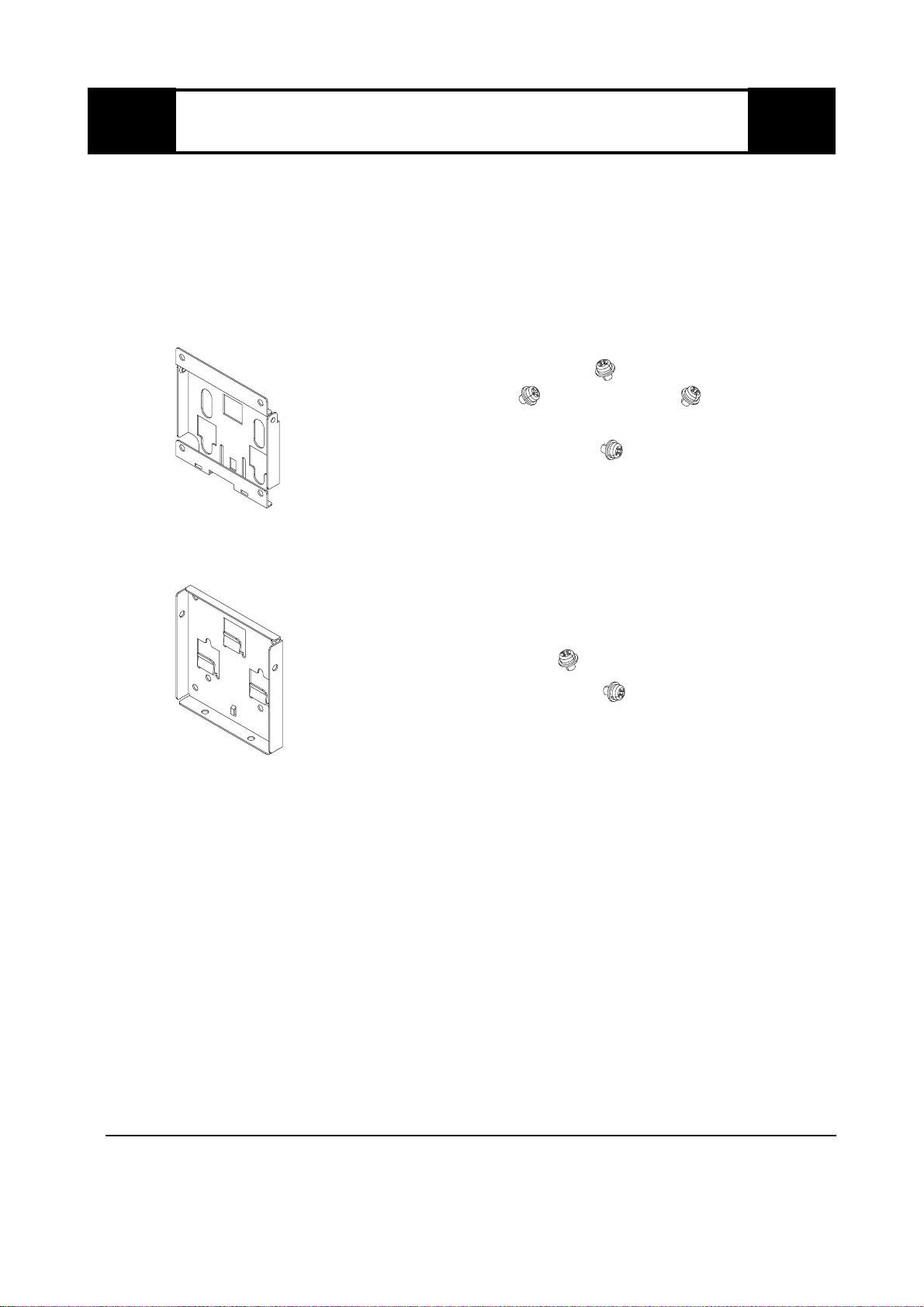
*1 The screws required to attach the Wall Mount Adaptor Plate to the wall are not included
in this package. Be sure to consider the wall's materials and strength when deciding on
the type of attachment screws to use.
Package Contents
Pro-face has thoroughly inspected this package's contents and quality prior to
shipping. If, however, any of the items listed here is broken or missing, or you
have any comments regarding the product, immediately contact your local Pro-
face distributor.
The Wall Mount Adaptor 's (Model No. CA1-WMALRG-01) package includes
the following items. Prior to using the unit, be sure to check that all the items are
included in the package.
Unit Rear Face Plate : 1
Unit Rear Face Attachment Screws: 4
Wall Mount Adaptor Plate*1 : 1
Wall Mount Adaptor Attachment
Screws: 2
-4-
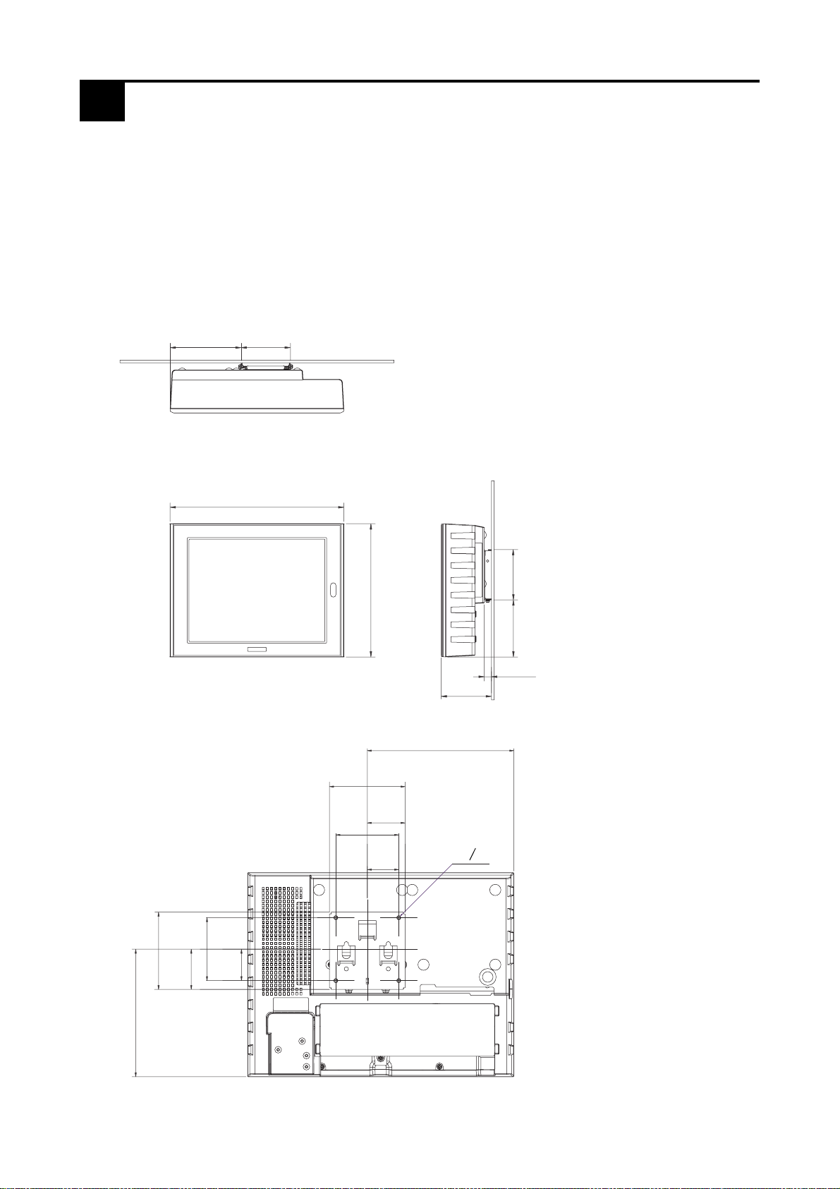
When using the Wall Mount Adaptor with PS-600G Series, PS-500P Series, GP-
2500/2600 Series, FP-2500/2600 Series, and GLC2600 Series units:
With these Units the optional Rear Cover is required. (CA1-RCVLRG-01) The
following drawings show the dimensions with the Wall Mount Adaptor attached
to this cover.
The following Unit is a PS-600G.
(Excluding
projections)
1External Dimensions
Rear
90[3.54]
13[0.51]
92[3.62]
317[12.48]
243[9.57]
Front Side
Wall Mount Adaptor dimensions
W90[3.54] x H92[3.62] x D13[0.51]
Top
104[4.09]
130[5.12]
92[3.62]
175[6.89]
90
[3.54] 45
[1.77]
75
[2.95]
37.5
[1.48]
48
[1.89] 75
[2.95]
152[5.98] 92
[3.62]
37.5
[1.48]
Unit: mm [in.]
4-o5
-5-
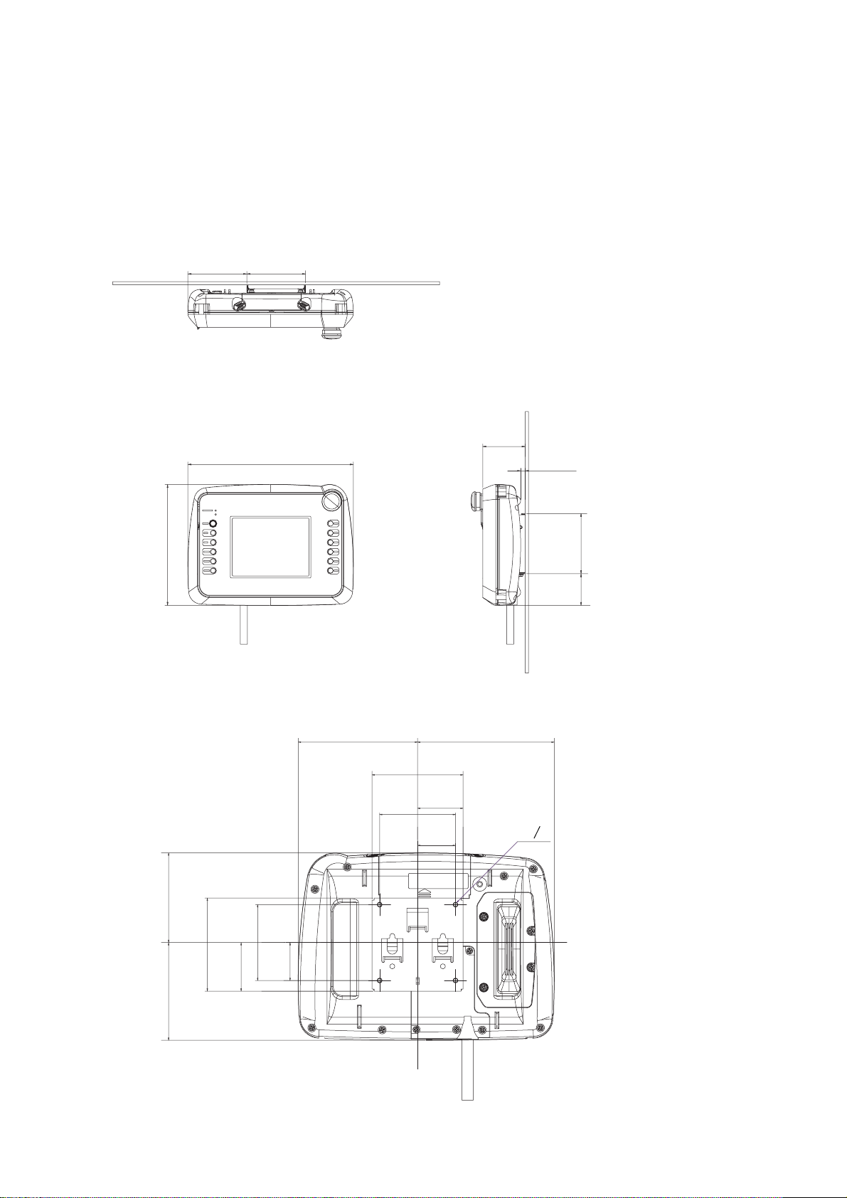
Front Side
Top
Rear
When using the Wall Mount Adaptor with a GP2000H Series unit:
The following drawings show the dimensions with the Wall Mount Adaptor
attached to the Unit.
The following Unit is a GP2301H.
Unit: mm [in.]
(Excluding
projections)
Wall Mount Adaptor dimensions
W90[3.54] x H92[3.62] x D13[0.51]
90[3.54] 90[3.54]
185[7.28]
253[9.96]
65
[2.56] 7[0.28]
49
[1.93] 92
[3.62]
118[4.65] 135[5.31]
90
[3.54] 45
[1.77]
75
[2.95] 37.5
[1.48] 4-o5
37.5
[1.48]
75
[2.95]
48
[1.89]
92
[3.62]
97[3.82] 89[3.50]

-6-
Structural
2Specifications
Be careful when installing the Wall Mount Adaptor to check on the envi-
ronment where it will be used, especially the levels of vibration that will
be present. Certain conditions can lead to an amplification of small si-
multaneous vibrations to produce a large overall vibration. This could
result in the contents of the screen being difficult to read, or make the
screen hard to operate, which could, in turn, cause an accident. To avoid
this problem, either position the Adaptor in a location where vibration is
minimal, or attach vibration absorbing material to the wall.
CAUTION
• Prior to installing the Wall Mount Adaptor, be sure to consider the weight of
the Unit, the force required to place the Unit on the wall, and the wall mate-
rial when deciding on the size/strength of the attachment screws. This is to
prevent the Unit or the Adaptor from accidentally falling from the wall.
• Be sure when installing the Adaptor not to pinch your fingers.
• Be sure to check that you have installed all the attachment screws prior to
using the Adaptor. This is to prevent the Unit from accidentally falling.
3Installation
WARNING
• Installing the Wall Mount Adaptor while power is supplied to the Unit may
lead to an electric shock. Prior to installing theWall Mount Adaptor, confirm
that the Unit's power supply is disconnected.
• Be sure to wear gloves, to prevent cuts or abrasions.
ExternalDimensions W90
[
3.54
]
xH92
[
3.62
]
xD13
[
0.51
]
mm
[
in.
]
Weight Approx.0.2[0.44]kg[lb.]
-7-
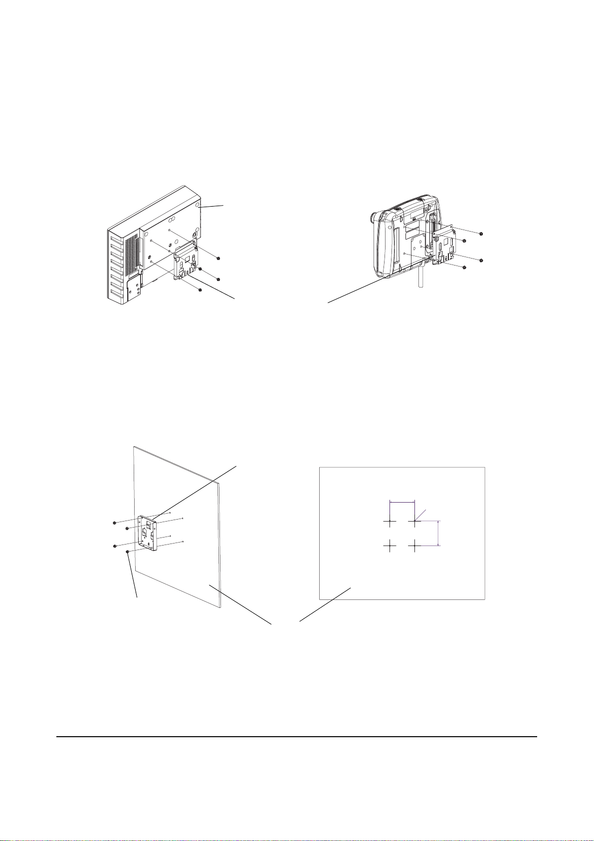
1) Attach the Unit Rear Face Plate to the Unit's Rear Cover.
(Fastening torque: 0.5 to 0.7 N•mm)
2) Attach the Wall Mount Adaptor Plate to the wall.
(this example uses M4 screws.)
Attachment dimensions
(Unit: mm [in.])
4-M4
Wall Mount
Adaptor
Plate
Wall
M4 Screws
With PS-600G Series, PS-500P Series, GP-
2500/2600 Series, FP-2500/2600 Series,
and GLC2600 Series units: With GP2000H Series units:
Unit Rear Face Plate
Rear Cover
(sold separately)
*1 The screws required to attach the Wall Mount Adaptor Plate to the wall are not included
in this package. Be sure to consider the wall's materials and strength when deciding on
the type of attachment screws to use.
75
[2.95]
75
[2.95]
-8-
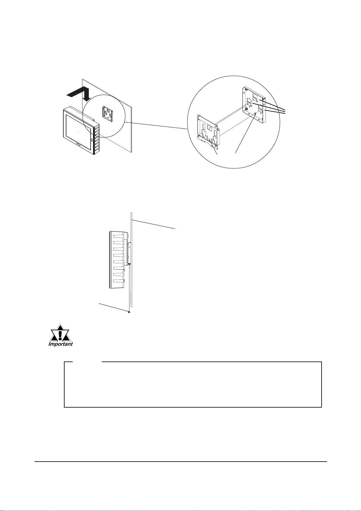
3) Hold the Unit firmly and place it over the Wall Mount Adaptor's Mounting
Tabs. The middle guide will help to position the unit.
4) The two (2) Set Screws at the bottom of the Adaptor are used to hold the
plates in place
Fastening torque: 0.5 to 0.7 N•m
Set Screws (2)
Guide
Mounting
Tabs
With PS-600G Series, PS-500P Series, GP-2500/2600 Series, FP-2500/2600
Series, and GLC2600 Series units, be sure to use these set screws.
© 2001 Digital Electronics Corporation. All rights reserved.
Note
Please be aware that Digital Electronics Corporation shall not be held
liable by the user for any damages, losses, or third party claims arising
from the uses of this product.
Digital Electronics Corporation
8-2-52 Nanko Higashi, Suminoe-ku, Osaka 559-0031, Japan
URL: http://www.pro-face.com/
Wall
Table of contents


