manuals.online logo
Brands
  1. Home
  2. •
  3. Brands
  4. •
  5. Yaesu
  6. •
  7. Receiver
  8. •
  9. Yaesu FR-101 User manual

Yaesu FR-101 User manual

FR-101
COMMUNICATIONS
RECEIVER
•
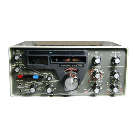
GENERAL
DESCRIPTION
The model FR-101
is
a solid-state communications
receiver designed
to
provide extreme flexibility
that
even
the most demanding amateur desires with provisions for
all mode reception
on
twenty
one
500
KHz amateur and
major shortwave broadcast bands from
160
through 2
meters. The versatile FR-I
01
receiver
is
capable
of
t.ransceive or independent receive and transmit function
with the matching
FL
-
101
transmitter or FT-101 E/
277E
transceiver.
New, solid-state technology, with features such
as
a
double-balanced mixer, offer unparalleled performance
and rejection
of
cross-modulation and intermodulation
interference.
All
circuits are composed
of
standard,
computor
type,
plug-in modules, for reliable operation
and service• simplicity. A linear tuning, temperature
compensated VFO with I KHz frequency readability
is
incorporated. A .100 KHz/25 KHz crystal calibrator
is
built-in. The FR-101 also includes fast
attack
/slow
release
AGC
for
SSB
or
AM
and fast release for
CW.
lf
desired, the
AGC
can be completely disabled. A built-in
noise blanker with adjustable threshold control provides
excellent elimination
of
most impulse type noise.
In addition to external VFO operation, a crystal
oscillator
is
built-in for crystal-control operation
of
4
channels of fixed frequency reception. The FR-I
01
includes a self-contained
AC
power supply · adjustable
from 100/
110/117
/
200
/
220
/
234
volt
AC
when the
primary power transformer winding
is
appropriately
wired.
The
SP
-101PB/277PB phone-patch and externa
l.
speaker
combination
is
a useful accessory for amateur operation.
SPECIFICATIONS
Frequency Range:
160m 1.8 -
2.0MHz
80 3.5 -4.0
60
4.5-
5.0*
40
7.0-
7.5
31
9.5 -10.0*
25
11.5 -12.0*
20 14.0 -14.5
19
15
.0 - 15.5*
16 17.5 -
18
.0*
15
21.0 -21.5
13
21.5 -22.0*
11
25.5 -26.0*
CB
27.0 -27.5*
lOA 28.0 -28.5
lOB
28.5 -29.0
lOC
29.0 -29.5*
lOD 29.5 -29.9*
VHF6m
50.0 -52.0* 52.0 -54.0*
VHF2m
144 -146* 146 -148*
ti
1 4.
0-
4.5**
ti
2 5.
0-
5.2**
ti
3 7.
5-
9.0**
ti
4 22.0 -27.0**
Type
of
Emission:
USB, LSB,
CW,
AM,
FM* or RTTY
Frequency Stability:
Within 100 Hz during any 30 minute period after
warm-up. Not more than 100
Hz
with 10% line
voltage variation.
Calibration Accuracy:
I KHz maximum after 100 KHz calibration.
Backlash:
Not more than 50 Hz.
Antenna Impedance:
50 ohm unbalanced nominal.
Power Requirement:
100/110/117
/2
00/220
/234 volt
AC
50/60
Hz or
13
.5 volt
DC
nominal.
Sensitivity:
SSB
and
CW
...
0
.3
µV for 10
dB
Noise plus Signal
to Noise Ratio on 14 MHz.
AM
.................
lµVon
14MHz.
FM
................. 12
dB
SINAD
Selectivity:
CW·N*
...........0.6 KHz/6 dB, 1.5 KHz/60
dB
CW,
SSB
, RTTY,
AM·N
............ 2.4 KHz
/6
dB, 4 KHz/60
dB
AM·W*
............ 6 KHz
/6
dB,
12
KHz/50
dB
FM*
................ 20 KHz
/6
dB, 45 KHz/50
dB
Harmonic & Other Spurious Response:
Image Rejection ............... Better than 60
dB.
Internal Spurious Signal ... Below I µV equivalent
to antenna input.
Automatic Gain Control:
AGC
threshold nominal I µV.
Selectable
AGC
time constant, fast or slow.
Fast attack time 3 milli-second and slow attack
time 4 milli-second. Fast release time 0.5 second
and slow release time 2 seconds.
Audio Noise Level:
Not less than
40
dB
below I watt.
Audio Output:
2 watts at 4 ohm impedance.
Audio Distortion:
Less than 10%at 2 watts output.
Dimensions:
340(W) x 153(H) x 285(D) mm.
Weight:
9
Kg.
*Options for FR-I0I Standard Type Receiver.
**Options for FR-101 Standard and Deluxe Type Receives.
SEMICONDUCTORS
Silicon TR:
FET:
IC:
18
x 2SC372Y, I x 2SC784R, 6 x 2SC735Y
Ix
2SA634
8 x 2SK19GR, 3 x 3SK35,
Ix
3SK40M
Ix
AN214,
Ix
TA7061AP, 2 x
CA
.3053,
I x MC1496G,
Ix
µPC-141C
Diode:
2 x IS2236,
1x1S2689,
5 x WZ090, I x WZ0109,
Ix
1S993, 6 x
1Sl555,
14 x
1Sl007,
4 x 1S188FM, 4 x V06B, 2 x TLR104
INSTALLATION
GENERAL
Carefully remove
the
FR-101 receiver from
the
carton
and examine
it
for any physical damage. Should any be
apparent,
notify
the
carrier immediately, stating the
damage in detail. Save
the
carton
and packing materials
for future use.
LOCATION
In
general,
the
location
of
the
FR-101
is
not
critical,
however it
is
recommended
that
excessively warm
locations be avoided. The FR-101 should be placed in a
location
that
has adequate space
to
permit free air
circulation through
the
cabinet opening.
POWER REQUIREMENT
Two prewired plugs are furnished
with
the
unit
for
AC
or
DC
voltage
operation.
The FR-101
is
supplied
with
a
multi-voltage power transformer and can be
operated
in
many areas
of
the
world where voltages
may
differ from
your
local supply voltage. Therefore, before connecting
the
AC
cord
to
the power
outlet,
be sure
that
the
voltage
marked on
the
rear
of
the
receiver agrees
with
the
local
AC
supply voltage.
CAUTION
PERMANENT DAMAGE WILL RESULT IF
IM-
PROPER
AC
SUPPLY VOLTA<:;E IS APPLIED TO THE
RECEIVER.
The FR-101 will
operate
satisfactorily from 12 volt,
negative ground
battery
source
by
connecting
the
DC
power cord
to
the
rear panel receptacle. The receiver
requires an average
of
0.5 amp. When making connec-
tions to
the
battery,
be certain
that
the
RED lead
is
connected
to
the positive (+) and
the
BLACK lead
to
the
negative (- ) terminals
of
the
battery.
Reversed connec-
tion could
permanently
damage
the
receiver circuitry.
ANTENNA AND GROUND
The FR-101
is
designed
for
use
with
a resonant
antenna
at
the
operating frequency
and
having an impedance
of
50
to
75 ohms. This requirement
is
easily
met
by
using a
center-fed dipole
antenna
resonated to
the
receiving
frequency and fed with coaxial cable.
For
amateur
band
operation,
any commercially designed
antenna
system
with
an impedance
of
50
to 75 ohms
may
be used.
Jf a
tuned,
open-wire transmission line
or
a long wire
antenna
is
used, a suitable
antenna
tuner
must be used
between
the
receiver and
antenna.
For
more detailed
description on antennas, please refer
to
"The
ARRL
Antenna
Hand
Book"
or
"The
Radio
Amateur
Hand
Book".
It
is
recommended
to
use
the
transmitting
antenna
when
the
FR-101
is
used
with
a transmitter
or
a transceiver.
Antenna
change-over
is
accomplished
by
an antenna
relay provided in our transmitter
or
transceiver.
The FR-101 should be connected t8 a good ground. The
ground lead should be connected to
the
terminal marked
GND located
on
the rear panel
of
the
receiver.
SPEAKER
A 4
ohm
speaker should be connected to the jack on
the
rear
of
the
chassis marked SP. One lead
of
the speaker
output
is
grounded to
the
chassis
so
that
the one lead
of
the speaker should be connected
as
illustrated
in
Figure
2.
Our accessory speaker model SP-10l B/
2778
or
SP-1
OlPB/277PB provides
the
correct impedance match
and matches in appearance with the FR-I 01.
HEADPHONE (
4 to 8
ohm
impedance)
A headphone jack
is
provided ·on
the
front panel for the
use
of
a high sensitivity headphone. When a low
sensitivity headphone
is
used, the 100 ohm resistor,
RI I, should
be
shorted for adequate volume. (Ref. to
Fig.
I)
MUTE
The MUTE
jack
on
the
rear
of
the chassis
is
wired
so
that
the
receiver will operate only when
the
inner-
conductor
of
this
jack
is
shorted
to
ground. When the
FR-101
is
operated
separately, and external muting
is
not
desired,
the
RCA plug
with
shorted inner and
outer
conductors
should be inserted
into
the MUTE jack. The
inner-conductor should, therefore, be connected to a
relay contact in
the
transmitter,
or
the transceiver,
which
is
normally
open
in transmit and grounded in
receive.
It
is
recommended
that
a shielded wire be used
for the interconnection between
the
transmitter or
transceiver.
111
IOOV
llOV
117V
200V
220V 234V
POWER TRANSFORMER
PRIMARY
CONNECTIONS
CONTROLS
AND
SWITCHES
The FR-101 has been specifically designed for ease
of
operation and versatility.
All
controls have been pro-
perly adjusted at
the
factory. Several panel controls and
switches are unusual in operation, and improper adjust-
ment may result in poor receiver performance. The
FRONT
(1)
MAIN
TUNING
The MAIN TUNING knob determines the frequency
which
you
are receiving.
(2)
BAND
The BAND switch
is
a
twenty
one position switch. The
tunable frequency range
of
each band
is
listed in the
spe:::ifications on page 2.
(3)
FUNCTION
SWITCH
The FUNCTION switch consists
of
five push
button
switches: POWER, STBY,
NB
, DIGIT and CALIB.
function
of
various controls and switches
is
described
in
the following section.
Be
certain
that
you understand
thoroughly the individual function
of
each before
operating the receiver.
PANEL
POWER: When this switch
is
in the depressed position,
the power transformer primary
is
connected
to
the power line for
AC
operation. A
separate
DC
cable
is
provided for connection
to
a battery for
DC
operation.
STBY: With this switch in the depressed position, the
receiver
is
muted.
NB
: With this switch in the depressed position, the
Noise Blanker
is
activated.
DIGIT: This switch
is
used
on
the digital readout
receiver
to
turn
off
the last digit
if
the flicker
is
annoying.
CALIB: With this switch in the depressed position, the
100 KHz/25 KHz calibrator
is
switched on.
A control is used for the calibration
of
-LL -.J
:_:.,._
1
--
-
.l.
1
-·
- '
-·
(4) MODE
The MODE switch
is
an eight position switch which
determines the appropriate detector and the filter in use.
In the
AM
position, a diode detector
is
incorporated and
the carrier oscillator
is
switched off. In the
CW,
RTTY,
and
SSB
(USB & LSB) positions, a ring demodulator
is
used
as
a detector with the appropriate carrier oscillator
turned on. In the
FM
position, an (optional)FM
detector unit
is
switched in. The appropriate filter
is
also
automatically selected by the MODE switch.
(5) AF-RF GAIN
The AF and
RF
GAIN control
is
a concentric double-
shaft potentiometer. The inner knob controls the audio
output
level
of
the receiver and the outer lever knob
controls the
RF
and IF gain
of
the receiver.
(6) SELECT
This switch provides the selection
of
an external VFO
or
one
of
four crystal-controlled oscillator positions. Nor-
mal operation
of
the FR-101 requires that the switch be
placed in the
"INT"
(Internal) position. When the switch
is
in the
"INT"
position, a red lamp marked VFO
is
lighted.
(7)
AGC
This switch selects the
AGC
time constant. In the
SLOW
position, the
AGC
time constant
is
0.75 second and
in
the FAST position, it
is
approximately 0.025 second. In
the
OFF
position,
AGC
voltage
is
not
generated. The
SLOW
position
is
normally used with
SSB
and
CW,
and
the FAST position
is
normally used for break-in
CW
and
RTTY. The
OFF
position may be used on
CW
under
difficult reception conditions in conjunction with the
RF Gain control
(8)
CLAR-TRANS
These controls use a concentric double-shaft potentiom-
eter. The CLAR (Clarifier) control -the inner knob -
provides a means
of
varying the receiver frequency a few
KHz to either side
of
the transmitting frequency when
the FR-101
is
used
as
a companion receiver
to
the
FL-101 or FT-101E/277E. Thus it
is
possible to set the
pitch
of
the voice you are receiving
to
the most readable
point without affecting your transmitting frequency.
The CLAR control may be switched
off
and the receiver
locked to the transmitting frequency
by
setting the
CLAR control to the
OFF
position. Normally, you will
want to keep the clarifier in the
OFF
position until the
initial contact
is
made. The CLAR control may then be
used to zero-in and correct any drift on the received
signal. With the clarifier
ON
position, a red lamp
is
lighted.
The TRANS (Transceiver) control
is
used to coincide the
receiving frequency with transmitting frequency when
the FR-101
is
used in conjunction with the FL-101 or
FT-101E/277E. Slowly advance the MONITOR knob
of
the FR-101 to monitor the transmitted signal, then
adjust the TRANS control for the most natural voice
quality while transmitting.
(9) PRESELECTOR
The PRESELECTOR control permeability-tunes the
antenna and RF coils
in
the receiver front-end. The scale
on this control
is
calibrated with the
wave
length
markings showing the correct setting for various bands.
This control has two pointers -red and white. The red
pointer corresponds
to
red band markings and the white
pointer to white band markings.
(10) MONITOR-SQUELCH
The MONITOR control
is
used to monitor the trans-
~itted
signal when the FR-101
is
used in transceive with
the FL-101 transmitter or FT-101E/277E transceiver.
The SQUELCH control adjusts the receiver squelch
threshold sensitivity in the
FM
reception mode (when
the optional
FM
detector unit
is
installed).
(11) VHF
The VHF switch selects the (optional) 6 meter and 2
meter VHF convertors. In normal reception, this switch
should be set to the HF position.
(12)
RF
ATT
The RF ATT
(RF
Attenuator) switch attenuates the
incoming signal
to
prevent over-loading
of
the front-end
when
an
extremely strong signal
is
present.
(13)
PHONE-RECORD
PHONE and RECORD jacks are provided for private
listening and recording when desired. The attenuator
resistor, R11,
is
connected to the PHONE jack in order
to
use
high sensitivity stereo headphones.
(14)
S-METER
The S-METER indicates the relative signal strength
of
a
received signal.
It
is
calibrated in S-Units from
S-1
to
S-9
and in
DB
over S-9.
(15) BAND INDICATOR
The BAND INDICATOR automatically indicates the
band in use when the BAND switch
is
set to the desired
band.
(16)
DIAL LOCK
The DIAL LOCK locks the dial for the dial calibration.
Fig.
I
Other manuals for FR-101

3

Other Yaesu Receiver manuals

Yaesu VR-500 User manual

Yaesu

Yaesu VR-500 User manual

Yaesu VR-5000 User manual

Yaesu

Yaesu VR-5000 User manual

Yaesu FT DX 3000 User manual

Yaesu

Yaesu FT DX 3000 User manual

Yaesu FT-710 Technical manual

Yaesu

Yaesu FT-710 Technical manual

Yaesu FT-2500M Administrator guide

Yaesu

Yaesu FT-2500M Administrator guide

Yaesu FRG-8800 User manual

Yaesu

Yaesu FRG-8800 User manual

Yaesu VR-5000 User manual

Yaesu

Yaesu VR-5000 User manual

Yaesu FRG-100 User manual

Yaesu

Yaesu FRG-100 User manual

Yaesu FRG-9600 User manual

Yaesu

Yaesu FRG-9600 User manual

Yaesu FRG-7700 User manual

Yaesu

Yaesu FRG-7700 User manual

Yaesu FT-560 User manual

Yaesu

Yaesu FT-560 User manual

Yaesu VR-500 User manual

Yaesu

Yaesu VR-500 User manual

Yaesu VR-120D User manual

Yaesu

Yaesu VR-120D User manual

Yaesu FT-1000 User manual

Yaesu

Yaesu FT-1000 User manual

Yaesu FRG-9600 User manual

Yaesu

Yaesu FRG-9600 User manual

Yaesu FRG-8800 User manual

Yaesu

Yaesu FRG-8800 User manual

Yaesu VR-5000 User manual

Yaesu

Yaesu VR-5000 User manual

Yaesu FRDX-400 User manual

Yaesu

Yaesu FRDX-400 User manual

Yaesu FR-100-b User manual

Yaesu

Yaesu FR-100-b User manual

Yaesu FRG-7 User manual

Yaesu

Yaesu FRG-7 User manual

Yaesu FRG-100 User manual

Yaesu

Yaesu FRG-100 User manual

Yaesu VR-120D Manual

Yaesu

Yaesu VR-120D Manual

Yaesu VR-120 User manual

Yaesu

Yaesu VR-120 User manual

Yaesu VR-5000 User manual

Yaesu

Yaesu VR-5000 User manual

Popular Receiver manuals by other brands

Televes ZAS HD SAT user manual

Televes

Televes ZAS HD SAT user manual

Realistic DX-75 Operating and service instructions

Realistic

Realistic DX-75 Operating and service instructions

Saris 4620 Assembly instructions

Saris

Saris 4620 Assembly instructions

Mini DTR 206C PVR user manual

Mini

Mini DTR 206C PVR user manual

RF Elements TwistPort manual

RF Elements

RF Elements TwistPort manual

Denon DN-200WS user guide

Denon

Denon DN-200WS user guide

Yamaha RX-V467 owner's manual

Yamaha

Yamaha RX-V467 owner's manual

Russound SaphIR 858 instruction manual

Russound

Russound SaphIR 858 instruction manual

Quasonix RDMS Firmware update procedure

Quasonix

Quasonix RDMS Firmware update procedure

Pioneer XV-HTD1 Service manual

Pioneer

Pioneer XV-HTD1 Service manual

ATZ HDMI-V2-44HE150 manual

ATZ

ATZ HDMI-V2-44HE150 manual

Sony XNV-770BT MyTomTom Specifications

Sony

Sony XNV-770BT MyTomTom Specifications

Grundig STR 7122 TWIN Service manual

Grundig

Grundig STR 7122 TWIN Service manual

Creative Blaster Modem user guide

Creative

Creative Blaster Modem user guide

Panduit ATLONA AT-OME-RX11 installation guide

Panduit

Panduit ATLONA AT-OME-RX11 installation guide

VOLTCRAFT UTPS-40 operating instructions

VOLTCRAFT

VOLTCRAFT UTPS-40 operating instructions

JVC KW-ADV794 instructions

JVC

JVC KW-ADV794 instructions

Litelink VT-1001 operating instructions

Litelink

Litelink VT-1001 operating instructions

manuals.online logo
manuals.online logoBrands
  • About & Mission
  • Contact us
  • Privacy Policy
  • Terms and Conditions

Copyright 2025 Manuals.Online. All Rights Reserved.