PRO.SIS.TEL. PST User manual

PRO. SIS. TEL.
Produzione sistemi telecomunicazioni
Antenna Rotator
Azimuth “D” DC version
ser’s manual
Rev.1.7b-usb
FCC
C.da Conghia 298 - 70043 Monopoli BA Italy
Tel-Fax ++39 080 8876607
E-mail:[email protected]
Copyright ® PRO.SIS.TEL. 2017

Warning
This manual must be read carefully before proceeding to assembly.
Warranty
1) The rotator with the control box, hereinafter called “product”, or “rotator”, is warranted for 2
years from date of purchase, provided that it is supported by the document of sale issued by the
manufacturer or authorized distributor.
2) The warranty covers replacement or repair of any defective component.
3) This warranty does not apply to product which have been subjected to misuse, ne li ence,
accident, incorrect wirin performed by the user, improper installation or non-compliance to
instructions furnished by us, dama e to product which has been repaired or altered without
authorization or to injury or loss resultin from careless maintenance. The warranty does not cover
dama e due to transportation and all causes not arisin from defects in workmanship, and faults
caused by adjustment of internal trimpots.
4) The warranty does not cover costs of transport or insurance for material returned to our
workshops.
5) The manufacturer is not responsible for personal injury or property dama e resultin from
improper or careless use of the product.
6) All product is tested after assembly and is supplied without defect. We exclude the
substitution or the prolon ation of warranty for a possible dama e.
7) After the 2 years warranty period, maintenance or repair will be subject to parts and labor
char es.
8) No person is authorized to assume for us any liability in connection with the sale of our
products.
9) This warranty does not cover dama e to people or thin s due to misuse, improper or
careless installation, or misunderstandin of instructions furnished by us.
10) The ri ht of recession must be exercised in accordin to the law.
11) Our products are subject to continuous improvement. We reserve the ri ht to implement
improvements and chan es without prior notification.
12) The le al code applyin in MONOPOLI, Italy, will apply, in cases of dispute.
13) Purchasers of product are deemed to accept para raphs 1, 2, 3, 4, 5, 6, 7, 8, 9, 10, 11, 12
and 13 as above.
Model: PST
S/N:
Date of purchase:
2

Important
Read this instruction manual carefully before attemptin to operate with the antenna rotator.
Save this instruction manual.
This instruction manual contains important safety and operatin instruction for antenna rotator.
Precautions
! WARNING, never connect or disconnect rotor cable or USB connectors while
power is on. This may results in electrical shock or burn.
Table of contents
Section 1: Description;
Section 2: Installation and use;
Section 3: Principle of operation ;
Section 4: Technical specifications;
Section 5: CD
Appendix 1: Declaration of conformity
Appendix 2: Warnin
Table:
Note:
Last up-date 28 March 2017
3

Section 1
The controller “D” version
1-1 Front panels description.
1 - POWER SWITCH (POWER)
Turns power ON and OFF
2 – Right lever: CW momentary switch
Pushin and holdin this switch will make the rotator turn clockwise
If you have used the preset, or computer control to start rotation, you can over-ride those commands
by momentarily depressin the switch.
3 – Left Lever: CCW momentary switch
Pushin and holdin this switch will make the rotator turn anti-clockwise
If you have used the preset, or computer control to start rotation, you can over-ride those commands
by momentarily depressin the switch.
4 - Display
The display will show the current bearin in de rees.
When the preset knob is turned, the display will show the preset bearin .
The decimal points on the LED display blink
* when you turn the tar et position knob on the front panel
* rotation be ins and is in pro ress
* when rotation is complete. At that time the display will blink for the pro rammed delay time before
further rotations are permitted. (Note - if the CW or CCW keys have been used, further rotations in the
same direction are not subject to this delay time)
5 - Preset rotating encoder
To preset rotation, turn the knob to the desired bearin . 3 seconds later, rotation towards the preset
position will start, with the display showin the bearin as it chan es. "Err" is displayed if the preset
knob is turned to a position outside the rotation limits.
4

1-2 Rear panel description.
1 – SB connector
Enables connection to a PC port for remote operation.
Pin 5 = computer round
Pin 2 = serial data out (to computer data in)
Pin 3 = serial data in (from computer data out)
2 - Rotator control cable male connector.
Connect the rotator to the controller
3 – AC Main Power male socket (230Vac or 115 Vac)
4 – Fuse holder.
19x5mm, 1.6A fuse is required.
1-3 “D” Controller features.
Warning:
this is a complex controller, make sure you understand before using it.
This controller has several features settable via SB serial port and some of such features are
even settable manually. A four ways dip-switch allows manual selections.
Controller parameters settable in either modes:
Soft start – Soft stop
South stop or North stop
Rotation range 360 or 500
Calibration
Off-set
Controller parameters settable via SB only:
Reverse delay
Preset delay
PWM duty cycles
Rotation range
Optimizer
Rotor chk
Controller display mode settable manually only:
Absolute or relative display mode.
Entering in Absolute mode
The controller uses an ADC which accepts 0-5V volta es. The antenna position volta e readout is
mapped to be inside the 0-5V ran e. In the absolute mode the display shows directly the rotator
position expressed in absolute de rees: you read values from 0 to 500. In the other operational modes
(north/south-stop) the absolute readin s are converted into different an ular position numbers, but
only for input/display purposes: internally the pro ram works with absolute an les.
The absolute mode can be only entered turnin -on the CBOX with the CW key pressed until the
display shows a blinkin “---“ (three minus): now you can release the key and the absolute mode is
entered. You can move the motor usin CW and CCW keys between the rotation limits.
To exit from such a mode you must recycle CBOX power (forcin another mode by USB command
isn’t effective).
In the absolute mode the rotor can be only operated by the CW/CCW
The absolute mode is usefull for CBOX calibration (see CALIBRATION para raph).
It is NOT recommended to turn bi antennas which need to be started and stopped softly.
5

The bearin values in de ree as shown by the display, are not absolute but relative, as show in the
conversion tables:
000 250 500
110
070
000 240
430
180 180270 090
340160Vdc
De .
absolute values
relative values
east side west sideNS SW E
outran e outran e
000 250 500
290
070
180 070
430
000 000090 270
340160Vdc
De .
absolute values
relative values
east sidewest side NS SW E
outran e outran e
South stop
North stop
South stop
North stop
That means when the VDC applied at ADC converter input is 000V or less, the ABS value is 000 and
the display show 110 de . if setted on South stop (default) while show 290 de . if setted on North
stop.
With an applied volta e of 2.50V the display will show 000 de when in South stop and 180 de when
in North stop, while with an applied volta e of 5V the display will show 250 de . when in South stop
and 070 de . when in North stop.
The on-board dip-switch
There is an on-board dip-switch that allows the user to chan e some operatin modes without usin
the supplied PC pro ram.
Remember that the dip-switch status is read only at power-up and copied into the EEPROM: you
must turn-off and turn-on the main power for a dip-switch chan e to be effective.
There are four switches:
#1: select the source of the three followin parameters: if ON the source is the other three
switches status, otherwise the relative EEPROM contents modifiable throu h the W command
#2: operatin mode: if ON is north-stop, otherwise is south-stop
#3: rotation ran e: if ON the rotation ran e is 0 to 500 absolute de rees, otherwise is 70 to
430 absolute de rees
#4: PWM: if ON the PWM is enabled, otherwise is disabled
The above parameters (ENA_PWM, LOWLIM, UPLIM, MODE) are not modifiable by USB serial
commands if the switch #1 is ON (dip-switch selected). LOWLIM and UPLIM chan e accordin ly with
the POS_OFFSET values.
Soft start and soft stop:
A MOSFET controlled PWM is included. When it is in active it permits soft-start and soft-stop for the
rotator.
Default value: included.
South stop or North stop:
Selectable via USB port or on board dip-switch, it’s possible to switch the display readin mode.
Default value: South stop.
Rotation range 360 or 500:
500 de rees of travel is enabled as the default value. This allows 70 de rees travel past 360 de rees,
in both directions. Some users may wish to limit travel to 360 de rees. There are two ways to do this
- By settin the on-board dip-switch as described above.
- By usin the supplied software - which will allow any limits to be set, to one de ree accuracy. Note -
Absolute values must be entered in the input fields.
Default value: 0-500 De rees
6
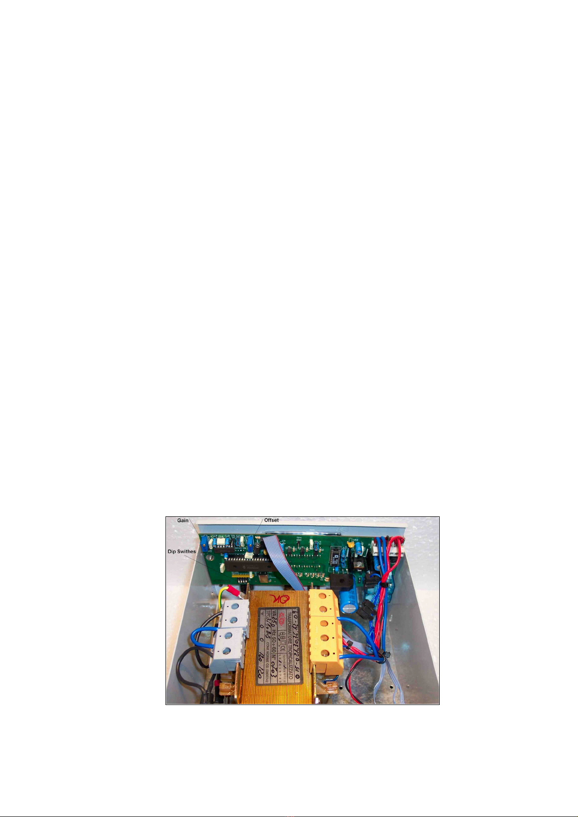
Calibration
Two on board trimmers are provided to calibrate the controller.
Note – adjustment of these trimmers which leads to a “fault” is not covered by the warranty.
Please do not adjust them if you are not sure of the correct procedure.
If necessary, you can recalibrate your controller via USB port. See calibration procedure issue.
Off-set
If the initial antenna direction it’s not coincident with the eo raphic direction, you can fix it manually
usin an on board off-set trimmer as well via USB.
Default value: 0
Revers delay
A reverse delay time is provided. This is to reduce stress on your rotator / tower and antenna systems
caused by too-rapid reversal of direction. The default time is 3 seconds, but this may be altered in the
software to suit your antenna system.
Preset delay
A preset delay time is provided. This allows you time to finalise the preset position before the rotator
starts to turn. The default is 3 seconds, which may be altered in the sofware.
PWM duty cycles
This feature controls the accelleration / deceleration of the rotator between rest and full rotation speed.
This feature is kind to your antenna system as it ives smooth startin and stoppin of your antenna.
Rotation range
This controller allows you to have 500 de rees of total rotor rotation ran e with 70 de rees of extra
travel for each side. An on board dip switch allow you to choose between two rotations ran es, 0-500
de rees (default) or 0-360 de rees.
Optimiser
If you select rotation by preset knob or computer control, the optimiser will determine the shortest
direction to tar et.
Rotor chk
If implemented, if you select a tar et with preset or computer control, the CPU will check the feeback
si nal from the rotator, and within 5 seconds will prevent the rotator from turnin in the event of an
abnormality.
Controller internal view
7

Calibration procedure.
Initial calibration is carried out in the factory.
Note – adjustment of these trimmers incorrectly may require service attention by your dealer.
THIS IS NOT COVERED BY THE WARRANTY and your dealer may raise a time and labour
charge for the work.
To use the on-board OFFSET trimmer to perform subsequent calibration
1. Turn the antenna to a known position if the true position differs from the controller display.
2. Adjust the on-board OFFSET trimmer until they are the same.
Note
The Calibration potentiometer will only permit a minor amount of adjustment. If your antenna position
is rossly incorrect, you will need to correct it by repositionin the antenna on the mast.
The complete calibration procedure is the SB - RS232 philosophy.pdf file for expert only)
1-4 The rotator
The rotator has a unique desi n. The motor is located on the side of the machine.
The motor output shaft terminates on a flan e, where different kinds of mast clamp, available from us,
may be fixed with bolts. Users may also supply their own clamp.
On the motor side is located a five-contact connector for motor power supply and potentiometer
terminals.
The potentiometer, used as the antenna position reader, is located inside the foot plate, and driven by
the transmission output shaft.
PST 110 - 71 - 61 PST2051 - 641
Rotator cable ends
Rotators end 110-71-61 2051-641 controllers end
8

Section 2
Installation and connections
2.1 npacking
After unpackin , immediately report any dama e to the deliverin carrier or dealer.
Keep the shippin cartoon.
2.2 Power supply connection
Connect the power cable and switch power on, display will show PHH and 110. Switch power OFF.
2.3 Rotator control cable preparation & connection
Before installin the rotator inside a tower, you need to prepare male connector for remote
control cable, make all connections and test rotator operation throu hly on the round, as described
below.
Connect the rotator and control box with a 5-core control cable. Two cores are used for the
motor DC power supply, and three for the position readin potentiometer. If the diameter of the control
cable is too thin, it will limit the volta e and reduce the torque.
Do not use cable with less than 0.5 mm² of section area.
Before connectin rotator and controller, make sure that power switch is OFF.
Cable plug Motor terminals board
Wire no. 1 must be connected to 1 (VDC motor power) >= 1mm²
Wire no. 2 must be connected to 2 (VDC motor power) >= 1mm²
Wire no. 3 must be connected to 3 (P to pot central lead)
Wire no. 4 must be connected to 4 (+5 Vdc pot lead)
Wire no. 5 must be connected to 5 (0 Vdc pot lead/GRO ND)
Warning: Improper wiring can result in damage to the rotator
circuitry when the power is swiched on.
THIS IS NOT COVERED BY THE WARRANTY.
2.4 Rotator cable inspection
Ensure the cable is correctly wired before connectin it to the controller.
Chekin the rotor cable you need a di ital multimeter.
Rotator truth table
Pins 1 and 2 (DC motor resistence = 4 ~19 ohm)
Pin 1 and 2 to ground = open
Pins 1-2 to pins 3-4-5 = open
Pins 3 and 4 = ~ 2.06K (positive wiper to potentiometer)
Pins 3 and 5 = ~ 7.65K (negative wiper to potentiometer)
Pins 4 and 5 = ~ 10K (entire potentiometer)
Pins 3-4-5 to ground = open
Those values are valid when rotator is pointin North, a small tollerance is acceptable.
If you don’t see these values, check your cable connections.
se truth table each time you notice something wrong on your controller.
2.5 Preinstallation check
! Warning, use only CW and CCW switch while preinstallation check is in pro ress.
Switch power ON, display will show PHH and after than the rotator position.
If display shows 110. or 2.50, check the connection cable.
Fully depress the CW lever switch for 1-2 seconds. the rotator should start to move in the CW
direction. Release the switch and try the same test for CCW. The opposite rotation will be a little
delayed by the preset delay time, which is normal. Note the controller display durin this test. The
9

readout should increase for CW and decrease for CCW. If these tests ive incorrect results, refer to
the troubleshootin section of this manual. If the results are correct, test full rotation to the electronic
limits in both CW and CCW directions. When this test has been performed turn the rotator to 000
de rees with the leverl switches. Then test the preset feature by settin a new direction with the preset
knob. Observe that the rotator will turn to that position and stop. The optimiser feature will ensure that
travel to the preset position is always in the shortest manner.
2.6 Troubleshooting
-Power
- Check the presence of the house power at power outlet;
- Check that the power cable plu s is correctly connected.
- Check the fuse. If it’s blown, replace it with one of the correct value and switch power on. If it
blows a ain, the user contacts the local service a ent.
-Motor turns in the wrong direction
-If while you were pushin CW switch the rotator started in counter clock wise sense, then the
motor is ettin reversed DC polarity. Chan e over the motor wires.
-Rotator follows the right CW and CCW commands but display shows the opposite.
- With a di ital voltmeter, check the presence of +5Vdc on the motor board, lead no. 4
If +5Vdc is not there, check the rotator cable connections/continuity.
- Display shows 110. and rotate only CW.
Potentiometer is misali ned, check the resistence as in the “truth table” if the resistence
valoue is lower than what it should be, than rotate the rotator CW till you et the ri ht
resistence valoue.
- Display shows 250. and rotate only CCW.
Potentiometer is misali ned, check the resistence as in the “truth table” if the resistence
valoue is hi her than what it should be, than rotate the rotator CCW till you et the ri ht
resistence valoue.
2.7 Rotator installation
Before drillin holes in the mountin plate, place the rotator inside the tower and adjust its
position so there will be no interference between rotator body and tower.
Put the antenna mast inside the mast clamp and lock centrally. The centre axis line must be within
0.5° of true.
By a pen, mark the position of the mountin holes on the mountin place, remove the rotator, and
drill the holes .
Use the four bolts with washers and self-lockin nuts to secure the rotator on the mountin plate.
Before ti htenin the bolts, insert the antenna mast in mast clamp, turn the rotator for 1 revolution
and adjust its position until the central axis line is within 0.5° . Now ti hten the bolts.
Note: Keep you rotator base dry, make sure that your tower rotator plate has enough
dreinage holes. Your rotator could get moisture in the base bell from the water standing on the
plate. If your tower rotator plate doesn’t have drainage holes and you can’t drill some, than put
some washers between the rotator base and the tower rotator plate.
2.8 Antenna direction adjustement
Antenna rotator ali nement is mechanical. After the antenna is installed on the mast, turn
rotator to the desired bearin . Unlock the bolts on mast clamp and with a ma netic compass turn the
antenna mast until the antenna beam direction is like that shown on the rotator control box. Lock the
antenna mast with the mast clamp bolts. The antenna beam direction now is fixed. If you want to
chan e it, you must rotate the antenna clamp on antenna mast. See Calibration Offset issue.
2.9 Rotator maintenance
The worm- eared motors are lubrificated for life and no maintenance is required. If you live in
an industrial zone or sea area, after a time you may have some corrosion to the outer casin . Rotators
are coated with anticorrosive paint at the factory and if repaintin is necessary, use ordinary
anticorrosive paint for ferrous metal.
10

Section 3
Principles of operation
3.1 Rotator
The rotator is manufactured with a worm-wheel eared motor drived by a hi h torque dc
motor.This method, normally used in heavy duty industrial and professional machinery, permits a very
hi h reduction ratio, with hi h power torque with both low power motor drive and hi h brake torque,
due the self-brakin property of the worm-wheel eared motor.
3.2 Electrical configuration
3.2.1 Indicator circuit
Three di it, 7 se ments led display are used for the direction indicator and the antenna direction
is displayed in de rees.
A 10 turns 10K potentiometer is used as position readin , only 1 turn of the 10 turns is used to
read antenna headin . See truth table.
3.2.2 Motor power switch
The motor is powered throu ht two 10 Amps lon life relays.
DRAW
: PST61DC, working basic block scheme
115V 60Hz
230V 50Hz
POWER
SUPPLY
AC
FILTER
PRO.SIS.TEL.
C.d Conghi 298
70043 Monopoli BA
tel.- f x ++39 80 8876607
www.prosistel.it
DRAWN BY
: Capitanio Piero
S/N
: A005
INPUT
RS232
0-12V c
0-9V c
CCW
ENCODER
CW
TRANSF
0-42V c
DISPLAY
CPU
DC
MOTOR
POWER
DATE
: December, 15 2003
REV
: 1
GND
POT.
2 -
3 P
4 +5VDC
1 +
M
11

Section 4
Specifications
4.1 Worm gear box
The worm ear box has a waterproof aluminium case conforms to the CEE 89/392/CEE
standard.
4.2 Motor
The motor, in a steel waterproof case conforms to CE and FCC class B.
4.3 Control unit
Microprocessor controlled di ital readout display havin USB serial port built inside.
The controller has ferrous parts painted. Conform to CE and FCC class B.
Rotators Specifications
METRICS
Model Wind
area
m2
Motor
torque
Kg/cm
Brake
torque
Nm
Vert.
load
Kg
Rotor
speed
360°
Variable
speed
Rotation
range
Motor
Volts
Wires
N. Redout RS232 Preset Kg
PST 641D 1.2 1.000 400 450 ± 60” yes 500 12 Vdc 5 digital yes yes 10
PST 2051D 2.5 2.000 600 650 ± 60” yes 500 12 Vdc 5 digital yes yes 14
PST 61D 3.9 3.800 1.180 850 ± 90” yes 500 12 Vdc 5 digital yes yes 25
PST 71D 8.8 6.000 2.172 1.000 ± 120” yes 500 24 Vdc 5 digital yes yes 35
PST 110D 10 6.000 3.400 1.200 ± 150” yes 500 24 Vdc 5 digital yes yes 45
S/ K
Model Wind
area
Sq.ft
Motor
Torque
Lbs ft
Brake
torque
Lbs ft
Vert.
load
Lbs
Rotor
speed
360°
Variable
speed
Rotation
range
Motor
Volts
Wires
N. Redout RS232 Preset Lbs
PST 641D 12 73 703 990 ± 60” yes 500 12 Vdc 5 digital yes yes 22
PST 2051D 25 147 1.000 1.430 ± 60” yes 500 12 Vdc 5 digital yes yes 31
PST 61D 39 280 2.100 1.870 ± 90” yes 500 12 Vdc 5 digital yes yes 55
PST 71D 88 1.032 4.032 2.200 ± 120” yes 500 24 Vdc 5 digital yes yes 77
PST110D 100 1.032 6.050 2.200 ± 150” yes 500 24 Vdc 5 digital yes yes 110
Note:
It is a good practice do not overpass the 50% of the maximum rotator wind load.
12

Section 5
With this user’s manual a CD is provided.
CD contains several folders in which there are some files with some extra informations about your
antenna rotator, as a copy of this manual as well.
We su est you pay attention on such extra informations, from which you can learn more about this
antenna rotator, but in meantime they are intended for expert technicians, so make sure to well
undestand what you are readin before to do anythin .
Setup Pro.Sis.Tel. Box D Vxxx.exe
an self-installer file, when you run it, the PC creates a copy of the contents of the CD and
install the software tool PRO.SIS.TEL. Box D V. X.XX.X
Drivers folder for PC SB port
Use such drivers when the PC operatin system does not have their own drivers.
Folder manuals and service documents
In this folder you will find a copy of the printed manual and service documents.
We recommend the readin of each of these.
Please read it carefully.
Service issues raised by incorrect use of the software are not covered by the warranty
This manual and the files on the CD are part of the equipment, store them carefully.
Dear customer,
thank you for purchase a Pro.Sis.Tel./BigBoyRotators, if you are happy with it please talk to
everybody, if you are unhappy with it please talk with us.
Your feed back and su estions, will be very appreciated, to improve our products.
Annamaria Fiume
IK7MWR
MADE IN ITALY
Protect your environment, in case of discontinuing of this unit, consign it to
specialized metal waste collector.
13

Appendix 1
DICHIARAZIONE DI CONFORMITA’
DECLARATION OF CONFORMITY
according to EN45014: 1998
Si dichiara che il prodotto: Rotore d’antenna mod. PST ……….D è conforme ai requisiti
essenziali delle seguenti direttive comunitarie:
This product: Antenna rotator model PST………..D is fully conforms
to the council directives:
-89 336 CEE
-92 31 CEE
-93 68 CEE marcatura CE per prodotti destinati ad essere utilizzati entro taluni limiti di
tensione
-93 97 CEE
-73 23 CEE
recepite dai seguenti decreti legislative
as amended by italian law.
-Nr. 791 del 18 10 1977 attuazione 73 23
-Nr. 615 del 12 11 1996 recepimento direttive 92 31 CEE, 93 68 CEE, 93 97 CEE
-Nr. 626 del 25 11 1996 attuazione della direttiva 93 68 CEE
-Nr. 277 del 31 07 1997 modifiche alla Nr. 626 del 25 11 96
E’ conforme ai requisiti di prodotto indicati dalle seguenti norme armonizzate:
It is conforms to product’s requirements as indicate in the following armonized rules:
- CEI EN 50082-1 Compatibilità elettromagnetica, norma generica sull’immunità. Ambienti
residenziali, commerciali ed industria leggera.
- CEI EN 50081-1 Compatibilità elettromagnetica, norma generica sull’emissione. Parte 1,
ambienti residenziali, commerciali e dell’industria generica.
- CEI EN 60335-1 Sicurezza degli apparecchi elettrici d’uso domestico e similare. Parte 1,
norme generali.
Esso è certific to FCC cl sse B.
It is cl ss B FCC certified.
In fede
Annmaria Fiume
Monopoli lì, 01 07 2005
14

PST61 - 71:
6 1 2"
(ø165mm)
ø12mm
1 2"
ø10mm
3 8"
PST2051:
5 1 8"
(ø130mm)
PST641:
4 1 2"
(ø115mm)
DRAW: Rotor plates holes diagram
PRO.SIS.TEL.
C.da conghia 298
70043 Monopoli BA
ITALY
www.prosistel.it
Note – this drawing is not to scale
15
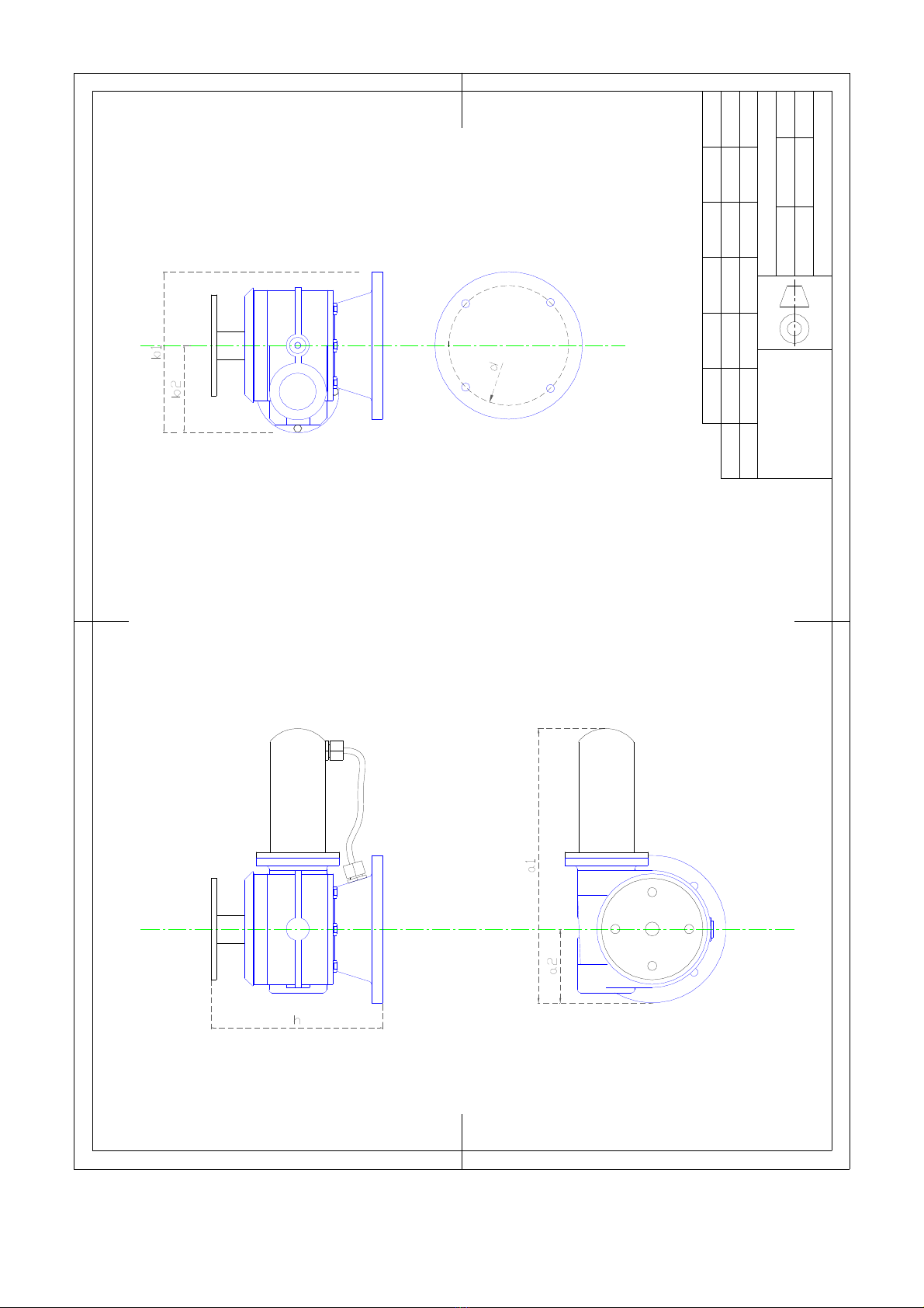
Dr w:
PST641-2051 general dimensions
Fixing plate
down view
PRO.SIS.TEL.
C.da Conghia 298
70043 Monopoli BA ITALY
tel. ++39 080 8876607
www.prosistel.it
280
298PST2051
PST641
a1
Drawn by:
Capitanio Piero
Scale:
1:1
a2
70
80
b1
150
175
b2
90
95
115
d
130
Note:
measurements in mm
Date:
May 05 2004
Checked by:
170
h
186
Rev:
16
PRO.SIS.TEL.
C.da Conghia 298
70043 Monopoli BA ITALY
tel. ++39 80 8876607
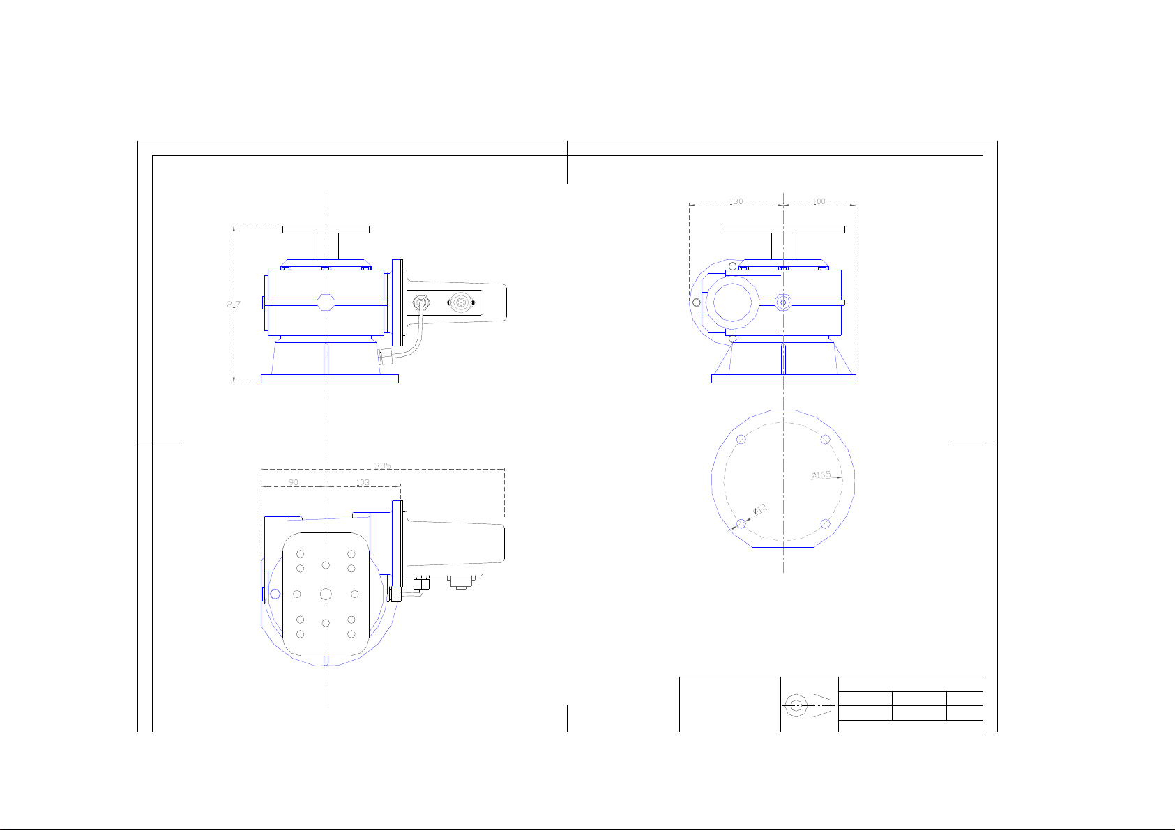
Dr w:
PST61D, general dim.
Drawn by:
Capitanio Piero
Checked by:
Rev:
Scale:
1:1
Date:
Feb 02 2007
Note:
measurements in mm
Fixing plate
down view
Serial number:

PRO.SIS.TEL.
C.da Conghia 298
70043 Monopoli BA ITALY
tel. ++39 80 8876607
Serial number:
Note:
measurements in mm
Dr w:
PST71DC general dimensions
Drawn by:
Capitanio Piero
Checked by:
Date:
April 09 2008
Scale:
1:1
Rev:
Fixing plate
down view
18

Company: Pro.Sis.Tel.
Draw: PST110D-Dimensions
Date: Sept. 03 2010
Rev:
Note: Quotes in millimeters
19
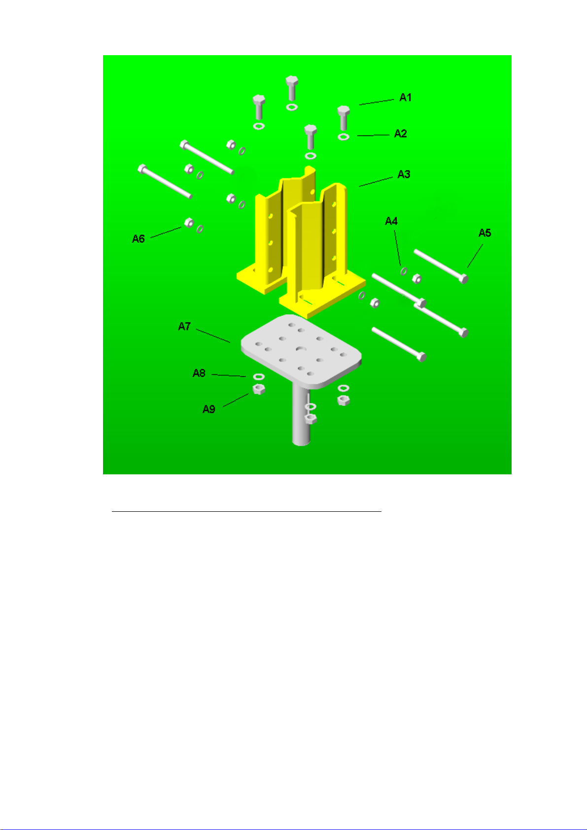
A1- Bolt, stainless steel, M10x40mm x 4
A2- Washer ø10mm, stainless steel x 4
A3- Mast clamps 3”, zinc galvanized steel x 2
A4- Split washer ø8mm, stainless steel x 6
A5- Bolt, stainless steel, M8x100mm x 6
A6- Stainless steel nut, M8 x 6
A7- Rotator shaft with plate, zinc galvanized steel x 1
A8- Split washer ø10mm, stainless steel x 4
A9- Nut M10, stainless steel x 4
This manual suits for next models
10
Other PRO.SIS.TEL. Antenna manuals

PRO.SIS.TEL.
PRO.SIS.TEL. PST-RD34T User manual

PRO.SIS.TEL.
PRO.SIS.TEL. PST-34TV User manual

PRO.SIS.TEL.
PRO.SIS.TEL. PST152VC Installation guide

PRO.SIS.TEL.
PRO.SIS.TEL. PST-40VF Installation guide

PRO.SIS.TEL.
PRO.SIS.TEL. PST-1524TV User manual

PRO.SIS.TEL.
PRO.SIS.TEL. PST-20VF Installation guide

PRO.SIS.TEL.
PRO.SIS.TEL. PST-32 Installation guide

PRO.SIS.TEL.
PRO.SIS.TEL. PST-152TV User manual

PRO.SIS.TEL.
PRO.SIS.TEL. PST-27 Installation guide

PRO.SIS.TEL.
PRO.SIS.TEL. PST-30VF User manual


