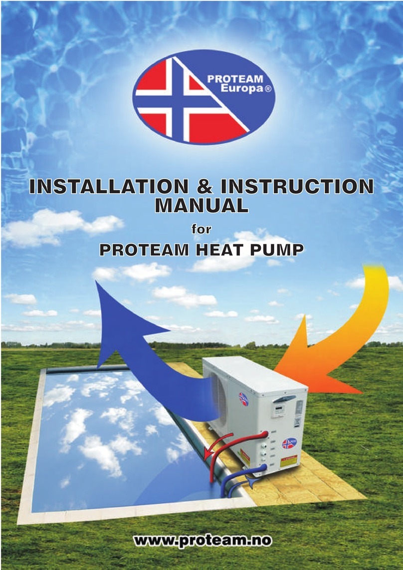
Pro-Team PC-NVI-90 User manual

Models:
PC-NVI-90
,
PC-NVI-110,
PC-NVI-140
,
PC-NVI-170,
PC-NVI-210,PC-NVI-230
PC-NVI-270,
PC-NVI-320
-
In
stallati
on
and
Operatio
n
Manual
-
PROTEAM EUROPA
Swimm
ing
Po
ol
Hea
t
Pump

THANK YOU
DearCustomer,
Thankyou for choosing Proteam Inverter Swimming PoolHeat Pumps for heating
or cooling your pool and extending your swimming season. The Proteam Inverter
Heat Pump is a smart heat pump which knows how to
heat your pool and
maintain its temperature in the most efficient way, thanks to the full
inverter
technology.
Pleasereadthemanualcarefullytogetthe maximum
benefitfromyourheatpump.
Please read carefully

TABLE OF CONTENT
INTRODUCTION.....................................................................................................................2
This manual .....................................................................................................................2
The unit .............................................................................................................................2
SAFETY INSTRUCTIONS.......................................................................................................2
ITEMS INSIDE PRODUCT BOX...................................................................................................4
OVERVIEW OF THE UNIT......................................................................................................5
EXPLODED VIEW........................................................................................................................6
INSTALLATION..............................................................................................................................7
Installation information...................................................................................................7
Condition of installation .................................................................................................7
Installation location.........................................................................................................7
Perfecting your installation ..............................................................................................7
Water connection.............................................................................................................7
Electrical connection ......................................................................................................9
Trial run..........................................................................................................................10
OPERATING THE UNIT ........................................................................................................10
Controller Instruction....................................................................................................10
Display Instruction...........................................................................................................11
Instruction for Function....................................................................................................12
Function Diagnosis..........................................................................................................12
PARAMETER CHECKING AND ADUSTMENT.....................................................................12
Parameter list..................................................................................................................13
Malfunctioning of the unit and maintenance....................................................................13
MAINTAINING THE UNIT .....................................................................................................16
Cleaning the pipe system in the heat exchanger........................................................17
Cleaning the air system......................................................................................................17
Winter Shutdown/Lay-up ..............................................................................................17
TROUBLESHOOTING ..........................................................................................................17
ENVIRONMENTAL INFORMATION............................................................................................18
DISPOSAL REQUIREMENTS...............................................................................................18
WIRING DIAGRAM................................................................................................................19
Specification ..........................................................................................................................21
READ THIS MANUAL CAREFULLY BEFORE STARTING UP THE UNIT. DO NOT
THROW IT AWAY. KEEP IT IN YOUR FILES FOR FUTURE REFERENCE.
BEFORE OPERATING THE UNIT, MAKE SURE THE INSTALLATION HAS BEEN CARRIED
OUT CORRECTLY BY A PROFESSIONAL DEALER. IF YOU FEEL UNSURE ABOUT
OPERATION, CONTACT YOUR DEALER FOR ADVICE AND INFORMATION.

INTRODUCTION
This manual
This manual contains important information about the unit. Please read this manual carefully before
you use and service the unit.
The unit
Heat pumps are one of the most economical systems to heat swimming pools efficiently. Using free
renewable energy from the air and earth, heat pumps deliver up to five times more energy than a
traditional heating system such as gas boiler or electric heater. Which means you can save 4/5
times the cost compared to other traditional heating systems. Swimming pool heat pumps extend
your swimming season and provide you a higher level of swimming comfort, allowing you to enjoy
your pool not only in summer, but also in spring, autumn and even winterif you like.
Ecological and economical heating
By making use of renewable energy available in the outside air, heat pumps consume less
energy and have lower carbon emissions. The use of the more environmentally-friendly
refrigerant gas R410A means that that negative effects ontheOzone are minimized.
Titanium heat exchanger
The titanium heat exchanger guarantees a longerlife span, ensuring the unit remains free from
corrosion and rust. The use of titanium means that the heat pumps can be used with all types of
water treatment systems including chlorine, iodine, bromine and salt.
Multiple functions
-Cooling, Heating and Auto functions are available
-Auto-operation, Auto-restart, Auto-defrost
-Timer on/off: no human input required
Wide temperature operating range: -10°C to46°C
Reliable operation
To ensure maximum performance and reliability of the unit, multiple protection deviceshave
been built into the units, including: insufficient water flow protection, high/lowpressure protection,
overload protection, compressor protection.
Safe use
Swimming pool heat pumps work without oil, gas or other hazardous substances, thereby
preventing risks associated with such materials. In addition, no gas connection or fuel tank is
required. So there is no risk of intoxication, smell or pollution from leakage.
Self-diagnosis
When there is a malfunction, the swimming pool heat pump will make a self-diagnosis by
displayingan error code on the control panel, making it possible to identify the potential problem
relatively quickly.
SAFETY INSTRUCTIONS
To prevent injury to users and others, or damage to property, the instructions below must befollowed.
Incorrect operation due to negligence or non-compliance with instructions may cause harm or damage.
Install the unit only when it complies with local regulations, by-laws and standards. Check the main
voltage and frequency. This unit is only suitable for earthed sockets, connection voltage 220 –240 V
~ / 50Hz.
The following safety precautions should always be taken intoaccount:
-Be sure to read the WARNING below before installing the unit.
-Be sure to observe the cautions specified here as they include important safety-related issues.
2

3
- Afterreadingtheseinstructions,besuretokeepthemhandyforfuturereference.
Donotinstalltheunityourself.
Incorrectinstallationcouldcauseinjuryduetofire,electricshock,theunitfallingorleakageofwater.
Consultthedealerfromwhomyoupurchasedtheunitoraspecializedinstaller.
Installtheunitsecurely.
Whenincorrectlyinstalled,theunitcouldfallcausinginjury.Wheninstallingtheunitinasmallroom,
please
takemeasures(likesufficientventilation)topreventasphyxiacausedbyleakageof
refrigerant.
Usethespecifiedelectricalwiresandconnectthewiresfirmlytotheterminalboard.
Incorrectconnectionandfixingcouldcauseafire.
Besuretousetheparts providedorspecifiedfortheinstallationwork.
Theuseofdefectivepartscouldcauseaninjuryduetopossiblefire,electricshocks,theunitfallingetc.
Perform the installation securely and refer to the installation instructions.
Incorrectinstallationcouldcauseinjuryduetofire,electricshocks,theunitfalling,leakageof
water etc.
Performelectricalworkaccordingtotheinstallationmanualandbesuretouseadedicatedcircuit
breaker.
Ifthecapacityofthepowercircuitisinsufficientorthereisanincompleteelectricalcircuit,itcouldresultinfire
orelectricshock.
Theunitmustalwayshaveanearthedconnection.
Ifthepowersupplyisnotearthed,youmust notconnecttheunit.
Neveruseanextensioncabletoconnecttheunittotheelectricpowersupply.
Ifthereisnosuitable,earthedwallsocketavailable,haveoneinstalledbyarecognizedelectrician.
Do not move/repair the unit yourself.
Beforeproceedingwithanymaintenance,serviceorrepairwork,theproductmustbeisolatedfromthe
mainelectricalsupply.Onlyqualifiedpersonnelshouldcarryoutthesetasks.Impropermovementor
repair ontheunitcouldleadtowaterleakage,electricalshock,injuryorfire.
Do notinstall the unitin aplacewhere there is a chanceof flammable gasleaks.
Ifthereisagasleakandgasaccumulatesintheareasurroundingtheunit,itcouldcauseanexplosion.
Perform the drainage/piping work according to the installation instruction.
Ifthereisadefectinthedrainage/pipingwork,watercouldleakfromtheunitandhouseholdgoodscould
getwet and bedamaged.
Do not clean the unit when the power is‘ON’.
Alwaysshutthepower ‘OFF’ whencleaningorservicingtheunit.Ifnot,itcouldcauseaninjuryduetothe
highspeedrunningfanoranelectricalshock.

4
Donotcontinuetoruntheunitwhenthereissomethingwrongorthereisastrangesmell.
Thepowersupplyneedstobeshut‘OFF’ tostoptheunit;otherwisethismaycauseanelectricalshockor
fire.
Donotputyourfingersorother objectsintothefan,or
evaporator.
Thefanrunsathighspeed,itcouldcauseserious
injury.
ITEMS INSIDE PRODUCT BOX
Beforestartingtheinstallation,pleasemakesurethatallpartsarefoundinsidethebox.
The UnitBox
Item
Image
Quantity
Proteam Inverter
Swimmingpoolheat
pump
1
Installationand
Operation Manual
1
Water Connectors
(50mm)
2
Winter Cover
1
Anti-vibration
rubber feet
4
Water Drainage Pipe
1

5
OVERVIEW OF THE UNIT
Unit Dimensions
Model
PC-NVI-90/110/140
PC-NVI-170/210/230
PC-NVI-270/320
A
986
1076
1176
B
668
720
822
C
356
426
451
D
405
456
481
E
608
628
723
F
116
116
116
G
380
330
500

6
EXPLODED
VIEW
No
Name
No.
Name
1
TopCover
14
BottomPanelcomponent
2
Electric box cover
15
Invertercompressor
3
Support frame
16
Middle-pressure switch
4
Electronic control components
17
Low-pressure switch
5
Finheatexchanger
18
Power waterproof cover
6
Fanblade
19
Controller
7
Middle panel
20
Rightpanel
8
AC fanmotor
21
Needle valve
9
Fan
22
Four-wayvalve
10
FrontPanel
23
High-pressurevalve
11
Discharge grill
24
Electronic expansion valve
12
Reactance waterproof box
25
Titaniumtubeheatexchanger
13
Reactance
26
Balance tank

7
INSTALLATION
Installationinformation
Theinformationgivenhereismeanttogivetheuserabetter
understanding of the installation.
Installation place
Installtheswimmingpoolheatpumponaflat,horizontal,andstablesurface.Maintain1m ofopenspacein
frontofthedischargegridsand3montheoutletsideof theventilator.Andreserveenoughspacetoallow
access to temperaturecontroller.
Makesurethatthedischargedairwillnotbebreathedin.
To perfect yourinstallation
--Avoiddirectingtheflowofventilatedairtowardsanoise-sensitive area,suchasaroomwindow.
--Avoidpositioningheatpumponasurfacethatcantransmitvibrationstothe house.
--Trytoavoidplacingapplianceunderatreeorexposedtowaterormud,whichwouldprobably make
maintenance more difficult.
Waterconnection
Theheatpumpisconnectedtoafiltrationcircuitwithaby-pass.
Itisimperativethattheby-passisplacedafterthepumpandthefilter.
The
by-passgenerallyconsistsof3valves.
Thismakesitpossibletoregulatethewaterflowwhichpassesthroughtheheatpumpandtoisolatetheheat
pumpcompletelyforanymaintenancework,withoutcuttingtheflowoffilteredwater.
Duringthefirstmonthsofuse,yourheatpumpissubjecttocondensation.Thiswillresultin
waterdischarge from the unit (can be a lot or a little dependingonthemoisturecontent),which
willgradually
diminish.

8
Tochannelcondensationflows,werecommendthatyouinstallacondensatedrainkit.For
this
purpose,theheatpumpmustberaisedbyatleast10cm.
Howtoinstallthecondensatedrainkit?
1.
Installyourheatpumpbyraisingit byatleast10cmusingsolid,moisture-resistantstuds.
2.
Connecttheexhausthosetothedrainholelocatedunderneaththeheatpump.
Hydraulic Connection

9
Electrical connection
Electricalsupplymustcorrespondtothatindicatedontheappliance.
Connectioncablesmust besizedaccordingtoappliancepowerandinstallationrequirements.
Please
refertobelowtable:
Thesevaluesare for indicative purposes only: consult a qualified electriciantodeterminetheexact
requirements foryourpool
installation.
Usethecableglandsandgrommetsprovidedinsidetheheatpumptoroutecables.
I
f
th
e
len
gth
o
f
y
o
u
r
c
ab
le
is
mor
e
th
an
10
mete
rs,
w
e
adv
is
e
y
o
u
t
o
se
e
k
adv
ic
e
fr
o
m
a
pr
o
fe
ss
i
on
al.
A
v
o
l
tage
v
ariati
on
o
f
±
10%
d
u
rin
g
o
p
er
a
tio
n
is
ac
c
ep
ta
ble.
T
h
e
p
o
w
er
s
u
pp
ly
li
n
es
mu
st
be
s
ecu
r
ely
fast
ened.
T
h
e
ca
ble
mu
st
b
e
su
ita
ble
f
o
r
o
u
tdo
o
r
u
s
e.
T
h
e
filte
r
mu
st
b
e
c
lean
ed
r
egu
la
rly
to
en
su
r
e
that
th
e
w
ate
r
in
th
e
sys
te
m
is
c
l
e
an
and
to
av
o
id
an
y
pr
o
ble
ms
r
elat
ed
t
o
di
r
t
o
r
c
l
o
ggin
g
o
f
th
e
filt
e
r
.
Heat
pump
Cabl
e
si
z
e
PC-NVI-90
3x2.
5mm
2
/A
WG
14
PC-NVI-110
3x2.
5mm
2
/A
WG
14
PC-NVI-140
3x4.
0mm
2
/A
WG
12
PC-NVI-170
3x4.
0mm
2
/A
WG
12
PC-NVI-210
3x6.
0mm
2
/A
WG
10
PC-NVI-230
3x6.
0mm
2
/A
WG
10
PC-NVI-270
3x10mm
2
/A
WG
8
PC-NVI-320
3x10mm
2
/A
WG
8

10
Trial run
Afterconnectingwatertothepoolsystem,completewithasuitableby-passandelectricalconnectionsbya
qualified engineer.
Besurethat:
1)
Appliance is horizontal and on a firmbase.
2)
Watercircuitiswellconnected(noleaksandnochanceofinjuryduetobadlyfittedhydrauliccouplings).
3)
Electricalcircuitiswellconnected(allcablestightenedcorrectlyatterminalsandintermediatecircuit
breaker), insulated and earthedcorrectly.
4)
The installation requirements described previously are strictly adhered to.
ATTENTION:THEHEATPUMPONLYFUNCTIONSWHENWATERFLOWISPRESENT.
Thenyoucanstartuptheheatpumpfollowingeverypointinthebeloworder:
-
Open by-pass valves
-
Start pool system pump
-
Turn on pool heat pump
-
Set regulation
OPERATING THE UNIT
Operatingtheunitcomesdowntooperatingthedigitalcontroller.
NEVERLETTHEDIGITALCONTROLLERGETWET.THISMAYCAUSEANELECTRICSHOCK
OR
FIRE.
NEVERPRESSTHEBUTTONSOFTHEDIGITALCONTROLLERWITHAHARD,POINTED
OBJECT.
THISMAYDAMAGETHEDIGITALCONTROLLER.
NEVERINSPECTORSERVICETHEDIGITALCONTROLLERYOURSELF, ASKAQUALIFIED
SERVICE
PERSONTODOTHIS.
1.
Controller Instruction
1.1
General
InputVoltage: DC12V
RS485 Communication
Short-Press for 1~5 seconds / Long-Press for 5 seconds.
NoButtonpressformorethan30s: controllersurfacewillexittodefault screen.
User
canoperatethecontrolleronlywhenthegreenislighton.
BacklightofScreenisorange, charactersandsymbolsareblack.
Operation temperature range for controller is -30
~
70
℃。
1.2
Dial Set
Onthebackofcontrollerboard, thereare4dials:
DP1
DP2
DP3
DP4
ONforbeepsound
ONforsoundwhenwater
flow warning
ONforbacklighton
always
ON for self-diagnose
status
OFFforno beepsound
OFFforno sound
when
water flow
warning
OFFforbacklighton
for 30s
OFFfornormal

11
1.3
Display and Operation Surface
2.
Display Instruction
2.1
Instruction for Buttons
Starton/off: Short-presstoturn on. Alsousercanpressthisbuttontoexitwhenfinishedsettingorchecking.
Running Modes: Short-Press to change mode. Long-Press
to enter menu option
Increase: Temperatureset+orpreviousscreen
Decrease: Temperature set - ornextscreen
BoostRunningmode:Short-presstoenter
SmartRunningmode:Short-presstoenter
SilentRunningmode:Short-presstoenter
2.2
Intructions for Display Symbols
:Heatingmode
:Cooling mode
:Auto-runmode
:Boost mode
:Smartmode
:Silentmode
:
wifi function
(when applicable)
:HeatPumpoutputcapacityinrealtime
:
Water in Temperature

12
:Water out Temperature
:Error Warning
2.3 Instruction for special display
When turn off the heat pump,screen only shows the last running symbol and data shows 0.
When heat pump has error warning,symbol displays and twinkles, water in area displays P or E, water
out area displays Error code.
3. Instruction for Function
3.1Switch Modes
When heat pump is on,short-press to switch Heat/Cool/Auto,each mode is available for selecting
Boost/Smart/Silent three modes
3.2Set Temperature
When heat pump is on,short-press or into water temperature setting surface. Water in area
temperature value twinkles,press or to select value,press to confirm and exit current setting.No
any set up after 30 seconds,the controller will save the last setting and go back to original surface.
3.3Set Parameter
When heat pump is on,Long-press into memu, displays Parameter Query,press or select
among Parameter Query/Parameter Setting/Debugging Status/History Fault.Short-press to confirm your
selction and switch to ,press or select, displays the value.
When on status of Parameter Setting , and display two“88”,it is asking you to enter your
password, press and to select,press to confirm.When password is right, displays
Parameter No. Displays related parameter value.
When on status of Debugging , displays the Number, 01 water pump debugging, 02 testing mode, and
displays ON or Off. The related mode symbol twinkles after entering into testing mode.
Display on each status:
Parameter Query Parameter Setting Debugging Status Error Query
Note:Value twinkles,means it is available for changing,or in verse
%

13
PARAMETER CHECKING ANDADUSTMENT
Parameter list
Someparameterscanbecheckedandadjustedbythecontroller.Belowistheparameterlist.
No.
Name
Instruction
1
Compressor running Frequency
Current hz
2
EEVOpendegree
Current Value/5
3
Ambient Temperature
Current
℃
4
Outlet Water Temp.
Current
℃
5
ExhaustgasTemp.
Current
℃
6
ReturngasTemp.
Current
℃
7
CoilTemp.
Current
℃
8
4-wayValveOutletTemp.
Current
℃
9
Water Circulaton Pump
0-off;1-on
10
4-wayValveStatus
0-off;1-on
11
Standby
/
12
Standby
/
13
Standby
/
14
Standby
/
15
Standby
/
16
Running Current of Compressor
Current*10
17
Voltage
Current/10
18
Standby
/
19
Standby
/
20
Standby
/
21
Fanspeed
Current/10
Malfunctioning of the unit
and maintenance
Whenanerroroccurs,ortheprotectionmodeissetautomatically,thecircuitboardandthewired
controllerwillbothdisplaytheerrormessage.
Error
Meaning
Analysis
Diagnosis
Solution
P01
Water
Flow
failure
1.
No water flow
2.
Flow switchfailure
3.
Water systemblock
1. Check if water in valve is
closedornowaterin
2.Check if flow switch is
blocked ordamaged
3. Check if “Y”-Shape filter
blocked
1.
Open the valve
2.
Replace flowswitch
3.Cleanorreplacefilter
P02
High pressure
protection
1.Water flow is
too
little
1. Check if water flow is not
enoughorwaterpumpflowis
not enough
1.Refillwaterorchangetoa
newpumpwith largerwater
flow;

14
2. High-pressureswitch
is damaged;
3.Refrigerant
system
block;
4. EEV deadlock 。
2.
Check if high-pressure
switch is off;
3.
Check if refrigerant system
is blocked
4.
Switch heat pump off,
then turn it on
and off to
check if EEV reset can
be heard.
2.
Replacehigh-pressure
switch
3.
Replace filter
4.ReplaceEEV
P03
Low pressure
protection
1. Lack of gas
2.Refrigerant
system
block;
3.Heat
pump
operating
range exceeded
1.
Check if gas system is
leaking
2.
Checkiffilter isblocked
3.
Check if ambient temp. or
watertemp.are above limits
1.
Repair the leak
and
re
fill with gas
2.
Replacefilter
P04
T3 Coil
overheat
protection
1.
Heat Pump fan
discharge area is
blocked
2.
Evaporator
is
blocked
3.
T3 coil sensor
position
was
changed
1.
checkifthedischargearea
is
open/free
2.
check if the evaporator is
blocked
3.
check if the coil sensor
resistancevalueiscorrect
1.
Free up the dischargearea
2.
Clean the evaporator
3.
Replacesensor
P05
Exhaust gas
temperature
protection
1.
Lack of gas
2.
sensor position
was
changed
1.
Check if there is a leak in
the refrigerant system
2.
Check if the sensor
r
esistancevalue iscorrect
1.
Repair leak and refill gas
2.
Replacesensor
P06
Outlet water
temperature
anti-freezing
protection
1.
lower waterflow;
2.
heat exchanger
blocked;
3.
Y-shaped filter
blocked;
4.
Overlow load。
1.
checkifthere is airin
water
system;
2.
Plateheatexchangerif
blocked;
3.
checkifY-shapedfilterhas
block;
4.
check that design of
indoor
water system is
appropriate, if
there is a
waterbypass。
1.
If there is a problem
with the drain valve,
replace it;
2.
blowplateheatexchanger
with water orhigh-pressure
gas from the opposite
direction;
3.
clean Y-shapedfilter;
4.
watersystemmusthave
bypass
P07
Pipe
temperature
anti-freeze
protection
1.
lack ofgas in system
2.
watersytemis
blocked;
3.
coolingsystemis
blocked。
1.
checksystemfor
leaks;
2.
check if Y-shaped filter
is blocked;
3.
checkifcoolingsystem
filter is blocked。
1.
Repair leak and refill gas
;
2.
Clean Y-shapedfilter;
3.
Change filter。
P08
High-pressure
2
protection
Highpressureswitch2
fault
checkifhighpressureswitch
2 cuts out under unit OFF
condition
changehighpressureswitch2
E01
Controller
communicatio
n failure
Communication
cable fault
Checkcommunicationcable
Re-connect or change
connectioncable
E02
TP1exhaust
gas
temperature
sensorfailure
sensor temperature
deviation or
failure
Check sensor
resistance
valueorif
sensoris faulty
Re-connect
cable or
change sensor

15
E03
T3 coil
temperature
sensorfailure
sensor temperature
deviation or
failure
Check sensor
resistance
valueorif
sensoris faulty
Re-connect
cable or
change sensor
E04
T4 ambient
temperature
sensorfailure
sensor temperature
deviation or
failure
Check sensor
resistance
valueorif
sensoris faulty
Re-connect
cable or
change sensor
E05
T5 liquidgas
temperature
sensor
sensor temperature
deviation or
failure
Check sensor
resistance
valueorif
sensoris faulty
Re-connect
cable or
change sensor
E06
THreturngas
temperature
sensorfailure
sensor temperature
deviation or
failure
Check sensor
resistance
valueorif
sensoris faulty
Re-connect
cable or
change sensor
E07
TWwatertank
temperature
sensorfailure
sensor temperature
deviation or
failure
Check sensor
resistance
valueorif
sensoris faulty
Re-connect
cable or
change sensor
E08
T6inletwater
temperature
sensorfailure
sensor temperature
deviation or
failure
Check sensor
resistance
valueorif
sensoris faulty
Re-connect
cable or
change sensor
E09
T7outletwater
temperature
sensorfailure
sensor temperature
deviation or
failure
Check sensor
resistance
valueorif
sensoris faulty
Re-connect
cable or
change sensor
E10
Controller and
Drive PCB
Communicate
failure
Communication
cable failure
Check if communication
cable is faulty
Re-connect
cable or
change connection cable
E11
reserved
Wiringerror
or
IPMmoduleinvalid
Check ifwiring
error
Re-connectcableorchangeIPMmodule
E12
reserved
E13
reserved
E14
reserved
E15
DC main cable
voltage very
low
E16
DC main cable
voltage very
high
E17
AC current
protection
(input side)
E18
IPM
module
abnormity
E19
PFC
abnormity
E20
Compressor
start
f
ailure
E21
Compressor
lacks phase
E22
IPM
module

16
reset
E23
Compressor
over-current
E24
PFC
module
extra high
temperature
E25
Current
detection
circuit
failure
E26
outofstep
E27
PFC
module
temperature
sensor
abnormity
E28
communication
failure
E29
IPMmodule
veryhigh
temperature
E30
IPM module
temperature
sensorfailure
E31
reserved
E32
IPM
adjustment
data
E33
IPM
adjustment
data
E34
ACinput
voltage
abnormal
E35
IPM
adjustment
data
E36
Reserved
E37
IPMmodule
current
frequency
limits
E38
IPMmodule
voltage
frequency
limits
E51
Failure of fan
motor drive
UNIT MAINTENANCE
Toprotectthepaintwork,avoidleaningorputtingobjectsontheunit.The outer casing of theheatpump
partscanbe
wipedwithadampclothanddomesticcleaner(Warning:Neverusecleaningagents
containingsand,
soda,acidorchlorideasthesecandamagethesurfaces)

17
Topreventfaultsduetosedimentsinthetitaniumheatexchangeroftheheatpump,ensurethattheheat
exchangercannotbecontaminated(watertreatmentandfiltersystemnecessary).Intheevent that
operatingmalfunctionsduetocontaminationoccur,thesystemshouldbecleanedasdescribedbelow.
(Warning:thefinsonthefinnedtubeheatexchangerhave sharp edges-dangerofbeingcut!)
Cleaningthepipesystemintheheatexchanger
Contamination in the pipes andheat exchanger can reduce the performance ofthe heat pump’s titanium
heatexchanger. Ifthis is the case, thepipesystemandheat exchangermust be cleanedbyatechnician.
Useonlypressurizeddrinkingwaterforcleaning.
Cleaning the air system
Thefinnedheatexchanger,ventilatorandcondensateoutflowshouldbecleanedofcontaminants(leaves,
twigs,etc.)beforeeachnewheatingperiod.Thesetypesofcontaminantscanbemanuallyremovedusing
compressedairorbyflushingwithcleanwater.
Itmaybenecessarytoremovethedevicecoverandairinletgridfirst.
Attention:Beforeopeningthedevice,ensurethatallcircuitsareisolatedfromthepowersupply.
Topreventtheevaporatorandthecondensatetrayfrombeingdamaged,donotusehardorsharpobjects
for cleaning.
Under extreme weather conditions (e.g. heavy snowfall), ice may form on the air intake and exhaust air
outlet
grids. If thishappens, theice must beremoved in thevicinity ofthe airintake and exhaustair outlet
grids
toensurethattheminimumairflowrateismaintained.
Winter Shutdown
Ifthereisachance offreezingafterthebathing-seasonhas ended, when theswimmingpool heating is
switchedoffandtheexternaltemperatureisexpectedtodropbelowtheoperatinglimit,thewatercircuit
of
theheatpumpshouldbecompletelydrained.Otherwise,suitableconstructionalmeasuresshouldbe
takenbythecustomertoprotecttheheatpumpagainstdamagefromfreezing.
Attention: The warranty does not cover damage caused by inadequate winterizing measures during the
winter.
TROUBLESHOOTING
This section provides useful information for diagnosing and correcting certain issues which may occur.
Beforestartingthetroubleshooting procedure,carryoutathoroughvisualinspectionoftheunitandlook
forobviousdefectssuchaslooseconnectionsordefectivewiring.
Beforecontactingyourlocaldealer,readthischaptercarefully,itwillsaveyoutimeandmoney.
WHENCARRYINGOUTANINSPECTIONONTHESWITCHBOXOFTHEUNIT,ALWAYS
MAKE
SURE
THATTHEMAINSWITCHOFTHEUNITISSWITCHED‘OFF’.
Theguidelinesbelowmighthelptosolveyourproblem.Ifyoucannotsolvetheproblem,consultyour
installer/localdealer.
Theheatpumpwillnotrun.
Please check whether:
Thereissupplyvoltage(trippedfuse,powerfailure).
Theoperatingswitchonthewirecontrollerisswitchedon,andwhetherthecorrectsetpoint
temperaturehasbeenset.
Thesettemperaturelevelcannotbereached.
Please check whether:

18
Thepermissibleoperatingconditionsfortheheatpumphavebeenadheredto(airtemperaturestoo
highortoolow).
Theairinletoroutletareaisblocked,restrictedorverydirty.
Thereareclosedvalvesorstop-cocksinthewaterpipes.
Thescheduledtimerdoesworkbuttheprogrammedactionsareexecutedatthewrongtime(e.g.1hour
toolateortooearly).
Please check whether:
Theclockandthedayoftheweekaresetcorrectly,adjustifnecessary.
Ifyoucannotcorrectthefaultyourself,pleasecontactyourafter-salesservicetechnician.
Work
ontheheatpumpmayonlybecarriedoutbyauthorizedandqualifiedafter-salesservice
technicians.
ENVIRONMENTAL INFORMATION
ThisequipmentcontainsfluorinatedgreenhousegasescoveredbytheKyotoProtocol.Itshouldonlybe
serviced or dismantled by professional trained personnel.
ThisequipmentcontainsR410Arefrigerantintheamountasstatedinthespecification.Donotdischarge
R410Aintotheatmosphere:R410A,isafluorinatedgreenhousegaswithaGlobalWarmingPotential
(GWP) =1975.
DISPOSALREQUIREMENTS
Dismantlingoftheunit,treatmentoftherefrigerant,ofoilandofotherpartsmustbedoneinaccordance
withrelevantlocalandnationallegislation.
Yourproductismarkedwiththissymbol.Thismeansthatelectricalandelectronicproducts
shall
notbemixedwithunsortedhouseholdwaste.
Donottrytodismantlethesystemyourself:thedismantlingofthesystem,treatmentofthe
refrigerant,ofoilandotherpartsmustbedonebyaqualifiedinstallerinaccordancewithrelevantlocal
and
national legislation.
Unitsmustbetreatedataspecializedtreatmentfacilityforre-use,recyclingandrecovery.Byensuringthat
thisproductisdisposedoffcorrectly,youwillhelptopreventpotentialnegativeconsequencesforthe
environmentandhumanhealth.Pleasecontacttheinstallerorlocalauthorityformoreinformation.
WIRINGDIAGRAM
Pleaserefertothewiringdiagramontheelectricbox.
This manual suits for next models
7
Table of contents
Other Pro-Team Heat Pump manuals
Popular Heat Pump manuals by other brands

Raypak
Raypak 6300tiPD Specifications

DeDietrich
DeDietrich ALEZIO O HYBRID user guide

Viessmann
Viessmann VITOCAL 300-A Installation and service instructions for contractors

STIEBEL ELTRON
STIEBEL ELTRON wpf 20 Operation and installation manual

Electrolux
Electrolux CXH09HL1W user manual

Dimplex
Dimplex LIK 8MER Installation and operating instructions