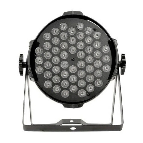
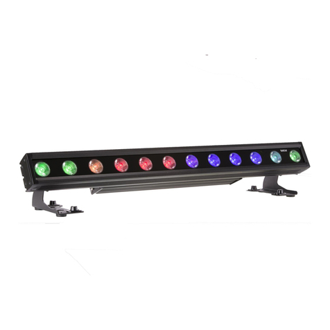
Pro-tec PAR 36 RGB LED MKII User manual

Bedienungsanleitung /
User Manual
PAR 36 RGB LED MKII
PAR 56 RGB LED MKII
PAR 64 RGB LED MKII
PAR 64 RGB LED 24x1W
mit DMX Ein- und Ausgang/
with DMX In- and Output

LED PAR
2
Inhalt
1
Sicherheitsbestimmungen...................................................................................................... 3
2
Einführung.............................................................................................................................. 3
3
Übersicht................................................................................................................................ 4
4
Funktionsauswahl .................................................................................................................. 5
4.1
Automatischer Wechsel ............................................................................................ 5
4.2
Auto Fade Modus...................................................................................................... 6
4.3
Manueller Modus....................................................................................................... 7
4.4
DMX Slave 5 Kanal Modus....................................................................................... 8
4.5
DMX Master 5 Kanal Modus..................................................................................... 9
4.6
DMX Slave 3 Kanal Modus..................................................................................... 12
4.7
DMX Master 3 Kanal Modus................................................................................... 13
5
Technische Daten ................................................................................................................ 14
Content
6
Safety Instructions................................................................................................................ 15
7
Introduction........................................................................................................................... 15
8
Overview .............................................................................................................................. 15
9
Function Selection................................................................................................................ 16
9.1
Auto change mode..................................................................................................16
9.2
Auto fade mode....................................................................................................... 17
9.3
Manual mode .......................................................................................................... 18
9.4
DMX slave 5ch mode.............................................................................................. 19
9.5
DMX master 5ch mode ........................................................................................... 20
9.6
DMX slave 3ch mode.............................................................................................. 22
9.7
DMX master 3ch mode ........................................................................................... 23
10
Technical Specifications....................................................................................................... 24

LED PAR
3
1 Sicherheitsbestimmungen
- Bitte packen sie das Gerät vorsichtig aus und prüfen sie es auf eventuelle Transportschäden.
- Das Gerät darf nicht in Betrieb genommen werden, nachdem es von einem kalten Raum in
einen warmen Raum gebracht wurde. Das hierbei entstehende Kondenswasser kann unter
Umständen ihr Gerät zerstören. Lassen sie das Gerät solange ausgeschaltet, bis es
Zimmertemperatur erreicht hat.
- Nehmen sie den LED Par Strahler erst in Betrieb, wenn sie sich mit dieser Bedienungs-
anleitung vertraut gemacht haben.
- Das Gerät muss unter allen Umständen trocken gehalten werden.
- Beim Austausch von Sicherungen verwenden sie bitte immer den gleichen Typ wie das zu
ersetzende Teil. Bitte benutzen sie nur original Ersatzteile.
- Das Effektgerät darf nicht an einen Dimmer angeschlossen werden.
- Vor Wartungsarbeiten wie z.B. Lampenwechsel das Gerät immer vom Netz trennen. Im
Gehäuse befinden sich keine Teile, die vom Benutzer gewartet werden können. Das Gehäuse
darf nur von qualifiziertem Fachpersonal geöffnet werden.
- Berühren sie kein Kabel oder andere Teile, während das Gerät in Betrieb ist.
Spannungsführende Teile können zu lebensgefährlichen Stromschlägen führen!
- Das Gehäuse darf während des Betriebs nicht mit bloßen Händen berührt werden.
- Benutzen sie dieses Effektgerät nicht in Gegenwart von kranken Menschen, wie z.B.
Epileptikern.
2 Einführung
Dieser High Power LED Strahler kann in verschiedenen Modi genutzt werden:
1. Master oder Slave mit 5 DMX Kanälen
2. Master oder Slave mit 3 DMX Kanälen
3. und im Stand Alone Modus
Die Besonderheit an diesem LED PAR ist, dass er als 4-Kanal DMX Controller verwendet werden
kann. In diesem Modus werden vier LED PAR-Strahler mit XLR-Kabel durch ihre DMX Ein- und
Ausgänge verbunden. Der erste LED PAR läuft im DMX Master Modus und sendet DMX Signale zu
den angeschlossenen LED PAR im Slave Modus. Es gibt verschiedene Muster, z.B. alle
angeschlossenen LED PAR-Strahlern laufen synchron, jeder einzelne PAR zeigt ein eigenes Muster,
Lauflichtprogramme oder Fade in - Fade out Muster. Die Abfolge der Muster können im Takt der
Musik oder durch einen Drehregler gesteuert werden. Die Musikempfindlichkeit ist einstellbar. Die
Farbmuster reichen von einem 100% Farbmodus, einem 100% / 50% Farbmodus bis zu einem 100% /
75% / 50% /25% Farbmodus. Die Farbwahl erfolgt zufällig.

LED PAR
4
3 Übersicht
Geräte Rückseite
Dieses Bild zeigt die Rückseite des LED PAR Scheinwerfers
DMX-Input (Eingang):
Schließen sie hier das Kabel eines externen DMX Steuergerätes an.
DMX-Input pin Signal
1 Erdung
2 Signal “-”
3 Signal “+”
DMX-Output (Ausgang):
Schließen sie hier das DMX Kabel für das nächste DMX Gerät an.
DMX-Output pin Signal
1 Erdung
2 Signal “-”
3 Signal “+”
Function (Funktionen):
Mit diesen 4 DIP Schaltern wird die Funktion des LED PAR eingestellt.
Pattern (Muster):
Die Funktion dieser 10 DIP Schalter ist abhängig von dem eingestellten Modus, z.B. werden im
Chaser Modus mit den DIP Schaltern die Muster eingestellt.
Speed (Geschwindigkeit):
Manuelle Geschwindigkeitseinstellung.
Music (Musik):
Empfindlichkeitseinstellung für das eingebaute Mikrofon im Falle von Musik-Ansteuerung.

LED PAR
5
4 Funktionsauswahl
Die Funktionen des LED PAR werden über die 4 DIP Schalter (SW1-SW4) auf der Rückseite des
Gerätes anhand dieser Tabelle eingestellt:
SW1 SW2 SW3 SW4 Funktion
0 0 0 X Automatischer Wechsel
1 0 0 X Auto Fade
0 1 0 X Manueller Modus
1 1 0 X DMX Slave 5 Kanal
0 0 1 X DMX Master 5 Kanal
1 0 1 X DMX Slave 3 Kanal
0 1 1 X DMX Master 3 Kanal
X X X 0 Geschwindigkeitskontrolle über den Drehregler, sofern der
gewählte Modus dies unterstützt.
X X X 1 Geschwindigkeitskontrolle über Musik, sofern der gewählte
Modus dies unterstützt.
0 = DIP Schalter ist aus
1 = DIP Schalter ist an
X = beachten sie die weiteren Informationen
DMX Funktionen
Aufbauen einer Kettenserie
Verbinden sie den DMX Ausgang des ersten DMX Gerätes mit dem DMX Eingang des zweiten
Gerätes usw. bis alle DMX Geräte verbunden sind. Das letzte DMX Gerät in dieser Kette benötigt zum
Abschluss einen 120 Ohm Wiederstand zwischen Signal “-“ und Signal “+”.
LED PAR als DMX Master
Im Master Modus arbeitet der DMX Strahler als Kontroller für die weiteren angeschlossenen DMX
Strahler. Wird der LED PAR-Strahler als Master genutzt, muss dieser der erste in der DMX Kette sein.
LED PAR DMX Slave
Im DMX Slave Modus arbeitet der DMX Strahler als normaler DMX Empfänger. Er wird über ein
externes DMX Gerät angesteuert.
4.1 Automatischer Wechsel
Der LED PAR zeigt verschiedene Farben in Abhängigkeit der Geschwindigkeit. In diesem Modus
arbeitet der LED PAR-Strahler im Stand-Alone Betrieb und wechselt die Muster automatisch. Der
DMX Aus- bzw. Eingang wird nicht benutzt.
Einstellung des Modus
Um in den Auto Change Modus zu gelangen, ändern sie die 4 DIP Schalter auf der Rückseite des
Gerätes wie in der folgenden Tabelle beschrieben:
SW1 SW2 SW3 SW4 Mode
0 0 0 X Automatischer Wechsel
0 = DIP Schalter ist aus
1 = DIP Schalter ist an
X = beachten sie die weiteren Informationen
Einstellung der Geschwindigkeit
Mit dem DIP Schalter 4 (SW4) können sie den die Ansteuerung der Geschwindigkeit anhand der
Tabelle ändern.
SW1 SW2 SW3 SW4 Mode
X X X 0 Geschwindigkeitskontrolle über den Drehregler
X X X 1 Geschwindigkeitskontrolle über Musik

LED PAR
6
0 = DIP Schalter ist aus
1 = DIP Schalter ist an
X = beachten sie die weiteren Informationen
Farbmuster Einstellung
Über die 10 DIP Schalter (SW1-SW10) auf der Rückseite des LED Strahlers können sie die
verschiedenen Farbmuster anhand der folgenden Tabelle einstellen:
SW1
SW2
SW3
SW4
SW5
SW6
SW7
SW8
SW9
SW10
Farbmuster Auswahl
1 0 0 0 0 0 0 0 0 0 100% Farbwechsel
0 1 0 0 0 0 0 0 0 0 100%, 50% Farbwechsel
1 1 0 0 0 0 0 0 0 0 100%, 75%, 50%, 25% Farbwechsel
0 = DIP Schalter ist aus
1 = DIP Schalter ist an
4.2 Auto Fade Modus
Der LED PAR erzeugt verschieden Farben, die je nach Einstellung ein-/ausblenden. Das Gerät
arbeitet im Stand-Alone Modus und der DMX Aus- bzw. Eingang wird nicht benutzt.
Einstellen des Modus
Um in den Auto Change Modus zu gelangen, ändern sie die 4 DIP Schalter (SW1-SW4) auf der
Rückseite des Strahlers wie in der folgenden Tabelle beschrieben:
SW1 SW2 SW3 SW4 Modus
1 0 0 X Auto Fade
0 = DIP Schalter ist aus
1 = DIP Schalter ist an
X = in diesem Modus kann die Geschwindigkeit nicht über den Drehregler oder die Musik gesteuert
werden.
Fade Geschwindigkeit
Die Fade Geschwindigkeit wird über die 10 DIP Schalter (SW1-SW10) auf der Rückseite des Gerätes
anhand der folgenden Tabelle eingestellt:
SW1 SW2 SW3 SW4 SW5 SW6 SW7 SW8 SW9 SW10 Fade Zeit
0 0 0 0 X X X 0 0 0 10:30 Minuten
1 0 0 0 X X X 0 0 0 2,5 Sekunden
0 1 0 0 X X X 0 0 0 5 Sekunden
1 1 0 0 X X X 0 0 0 10 Sekunden
0 0 1 0 X X X 0 0 0 20 Sekunden
1 0 1 0 X X X 0 0 0 40 Sekunden
0 1 1 0 X X X 0 0 0 80 Sekunden
1 1 1 0 X X X 0 0 0 160 Sekunden
0 0 0 1 X X X 0 0 0 320 Sekunden
0 = DIP Schalter ist aus
1 = DIP Schalter ist an
X = beachten sie die folgende Tabelle (Farbmuster Einstellungen)
Farbmuster Einstellung
Die Fade Farbmuster werden über die 10 DIP Schalter (SW1-SW10) auf der Rückseite des Gerätes
anhand der folgenden Tabelle eingestellt:
SW1
SW2
SW3
SW4
SW5
SW6
SW7
SW8
SW9
SW10
Farbmuster Einstellungen
X X X X 1 0 0 0 0 0 100% Farbwechsel, Fade in und Fade out
X X X X 0 1 0 0 0 0
100%, 50% Farbwechsel, Fade in und Fade
out
X X X X 1 1 0 0 0 0
100%, 75%, 50%, 25% Farbwechsel, Fade in
und Fade out

LED PAR
7
X X X X 0 0 1 0 0 0 100% Farbwechsel, Fade in
X X X X 1 0 1 0 0 0 100%, 50% Farbwechsel, Fade in
X X X X 0 1 1 0 0 0 100%, 75%, 50%, 25% Farbwechsel, Fade in
0 = DIP Schalter ist aus
1 = DIP Schalter ist an
X = beachten sie die letzte Tabelle (Fade Geschwindigkeit)
4.3 Manueller Modus
In diesem Modus stellen sie für den LED PAR eine feststehende Farbe ein. Das Gerät arbeitet im
Stand Alone Modus und der DMX Aus- bzw. Eingang wird nicht benutzt.
Einstellen des Modus
Um in den Manuellen Modus zu gelangen, ändern sie die 4 DIP (SW1-SW4) Schalter auf der
Rückseite des Strahlers wie in der folgenden Tabelle beschrieben:
SW1 SW2 SW3 SW4 Modus
0 1 0 X Manueller Modus
0 = DIP Schalter ist aus
1 = DIP Schalter ist an
X = in diesem Modus kann die Geschwindigkeit nicht über den Drehregler oder die Musik gesteuert
werden.
Farbmuster Einstellung
Rote Farbe
Die Rote Farbe wird über 10 DIP Schalter (SW1-SW10) auf der Rückseite des Gerätes anhand der
folgenden Tabelle eingestellt:
SW1
SW2 SW3 SW4 SW5 SW6 SW7 SW8 SW9 SW10 Rote Farbe / Helligkeit
0 0 0 X X X X X X 0 0%
1 0 0 X X X X X X 0 14%
0 1 0 X X X X X X 0 28%
1 1 0 X X X X X X 0 42%
0 0 1 X X X X X X 0 57%
1 0 1 X X X X X X 0 71%
0 1 1 X X X X X X 0 85%
1 1 1 X X X X X X 0 100%
0 = DIP Schalter ist aus
1 = DIP Schalter ist an
X = beachten sie die folgenden Tabellen
Grüne Farbe
Die Grüne Farbe wird über 10 DIP Schalter (SW1-SW10) auf der Rückseite des Gerätes anhand der
folgenden Tabelle eingestellt:
SW1 SW2 SW3 SW4 SW5 SW6 SW7 SW8 SW9 SW10 Grüne Farbe / Helligkeit
X X X 0 0 0 X X X 0 0%
X X X 1 0 0 X X X 0 14%
X X X 0 1 0 X X X 0 28%
X X X 1 1 0 X X X 0 42%
X X X 0 0 1 X X X 0 57%
X X X 1 0 1 X X X 0 71%
X X X 0 1 1 X X X 0 85%
X X X 1 1 1 X X X 0 100%

LED PAR
8
0 = DIP Schalter ist aus
1 = DIP Schalter ist an
X = beachten sie die vorhergehende Tabelle
Blaue Farbe
Die blaue Farbe wird über 10 DIP Schalter (SW1-SW10) auf der Rückseite des Gerätes anhand der
folgenden Tabelle eingestellt:
SW1 SW2 SW3 SW4 SW5 SW6 SW7 SW8 SW9 SW10 Blaue Farbe / Helligkeit
X X X X X X 0 0 0 0 0%
X X X X X X 1 0 0 0 14%
X X X X X X 0 1 0 0 28%
X X X X X X 1 1 0 0 42%
X X X X X X 0 0 1 0 57%
X X X X X X 1 0 1 0 71%
X X X X X X 0 1 1 0 85%
X X X X X X 1 1 1 0 100%
0 = DIP Schalter ist aus
1 = DIP Schalter ist an
X = beachten sie die vorhergehenden Tabellen.
4.4 DMX Slave 5 Kanal Modus
Das Gerät wird über 5 DMX Kanäle angesteuert. Mit den DIP Schaltern 1 bis 9 wird der erste DMX
Kanal auf Empfang gesetzt.
Einstellen des Modus
Um in den 5 Kanal DMX Slave Modus zu gelangen, ändern sie die 4 DIP Schalter (SW1-SW4) auf der
Rückseite des Strahlers wie in der folgenden Tabelle beschrieben:
SW1 SW2 SW3 SW4 Modus
1 1 0 X DMX Slave 5 Kanal
0 = DIP Schalter ist aus
1 = DIP Schalter ist an
X = beachten sie die folgende Tabelle
Einstellen der Geschwindigkeit
Mit dem DIP Schalter 4 (SW4) können sie den die Ansteuerung der Geschwindigkeit anhand der
Tabelle ändern.
SW1 SW2 SW3 SW4 Mode
X X X 0 Geschwindigkeitskontrolle über den Drehregler, sofern der
gewählte Modus dies unterstützt.
X X X 1 Geschwindigkeitskontrolle über Musik, sofern der
gewählte Modus dies unterstützt.
0 = DIP Schalter ist aus
1 = DIP Schalter ist an
X = beachten sie die letzte Tabelle

LED PAR
9
DMX Einstellungen im 5 Kanal Betrieb
Die Tabelle zeigt den DMX Wert, der von einem externen DMX Kontroller zum LED PAR gesendet
werden muss:
Kanal 1, Wert Funktion
0 - 63 RGB Control, Kanal 2 = rot, Kanal 3 = grün, Kanal 4 = blau
64 – 127 7 Farbwechsel, Kanal 5 = Geschwindigkeitssteuerung
128 – 191 7 Farbwechsel, Kanal 5 = Geschwindigkeitssteuerung
192 – 255 3 Farbwechsel, Kanal 5 = Geschwindigkeitssteuerung
Kanal 2, Wert Funktion
0 – 255 Rot 0% – 100%
Kanal 3, Wert Funktion
0 – 255 Grün 0% – 100%
Kanal 4, Wert Funktion
0 – 255 Blau 0% – 100%
Kanal 5, Wert Funktion
0 - 10 Keine Funktion – keine Geschwindigkeit
11 - 100 Wert 11 bis 100, von schnell nach langsam
101 - 150 Keine Funktion – keine Geschwindigkeit
151 - 255 Geschwindigkeitssteuerung durch den LED-Strahler, Musik oder über den
Drehregler
Einstellung des ersten DMX Empfangskanals
Der Wert der DIP Schalter 1 bis 9 ist ein Binär Code. Um den gewünschten DMX Empfangskanal
einzustellen, müssen sie die DIP Schalter (SW1-SW10) wie in der folgenden Tabelle setzen:
SW1 SW2 SW3 SW4 SW5 SW6 SW7 SW8 SW9 SW10 Erster DMX Empfangskanal
1 0 0 0 0 0 0 0 0 0 1
0 1 0 0 0 0 0 0 0 0 2
0 0 1 0 0 0 0 0 0 0 4
0 0 0 1 0 0 0 0 0 0 8
0 0 0 0 1 0 0 0 0 0 16
0 0 0 0 0 1 0 0 0 0 32
0 0 0 0 0 0 1 0 0 0 64
0 0 0 0 0 0 0 1 0 0 128
0 0 0 0 0 0 0 0 1 0 256
0 = DIP Schalter ist aus
1 = DIP Schalter ist an
Anmerkung:
Wenn alle Schalter auf Null stehen, ist der erste DMX Empfangskanal 1. Falls nur der Schalter 1 an
ist, ist der erste DMX Empfangskanal Kanal 1.
Der maximale erste Empfangskanal ist Kanal 508. Falls der erste Empfangskanal höher als Kanal 508
gewählt wird, ist der maximale Empfangskanal dennoch Kanal 508.
4.5 DMX Master 5-Kanal Modus
In diesem Modus ist der LED PAR ein 5 Kanal DMX Kontroller. Dieser 5 Kanal Modus ist für die neuen
und alten LED PAR-Strahler entwickelt worden. Die angeschlossenen Slaves müssen in den 5 Kanal
DMX Slave Modus gesetzt sein (siehe Kapitel 4.4).

LED PAR
10
Mode Einstellungen
Um den DMX Master 5 Kanal Modus einzustellen, müssen sie auf der Rückseite des LED PAR die 4
DIP Schalter(SW1-SW4) anhand der folgenden Tabelle einstellen:
SW1 SW2 SW3 SW4 Modus
0 0 1 X DMX Master 5 Kanal
0 = DIP Schalter ist aus
1 = DIP Schalter ist an
X = beachten sie die folgenden Informationen
Einstellen der Geschwindigkeit
Mit dem DIP Schalter 4 (SW4) können sie den die Ansteuerung der Geschwindigkeit anhand der
Tabelle ändern.
SW1 SW2 SW3 SW4 Modus
X X X 0 Geschwindigkeitskontrolle über den Drehregler
X X X 1 Geschwindigkeitskontrolle über Musik
0 = DIP Schalter ist aus
1 = DIP Schalter ist an
X = beachten sie die vorhergehenden Informationen
DMX Einstellungen im 5-Kanal Betrieb
Der LED PAR im Master Modus sendet die DMX Daten wie in der folgenden Tabelle beschrieben. Der
angeschlossene Slave muss eingestellt sein wie in Kapitel 4.4 beschrieben.
1. DMX Kanal = 0, RGB control
2. DMX Kanal = rot
3. DMX Kanal = grün
4. DMX Kanal = blau
5. DMX Kanal = 0, keine Funktion, keine Geschwindigkeit
6. DMX Kanal = 0, RGB control
7. DMX Kanal = rot
8. DMX Kanal = grün
9. DMX Kanal = blau
10. DMX Kanal = 0, keine Funktion, keine Geschwindigkeit
11. DMX Kanal = 0, RGB control
12. DMX Kanal = rot
13. DMX Kanal = grün
14. DMX Kanal = blau
15. DMX Kanal = 0, keine Funktion, keine Geschwindigkeit
16. DMX Kanal = 0, RGB control
17. DMX Kanal = rot
18. DMX Kanal = grün
19. DMX Kanal = blau
20. DMX Kanal = 0, keine Funktion, keine Geschwindigkeit
Einstellen der Farbmuster
Über die 10 DIP Schalter (SW1-SW10) auf der Rückseite des Gerätes werden die verschiedenen
Farbmuster anhand der folgenden Tabellen eingestellt:

LED PAR
11
Farbmuster
Alle LED PAR-Strahler sind an und wechseln die Farbe.
SW1
SW2
SW3
SW4
SW5
SW6
SW7
SW8
SW9
SW10 Farbmuster
0 0 0 0 0 0 0 0 0 0 4 Kanal, Muster 1, alle an, alle machen das Selbe
1 0 0 0 0 0 0 0 0 0 4 Kanal, Muster 2, alle an, alle machen das Selbe
0 1 0 0 0 0 0 0 0 0 4 Kanal, Muster 3, alle an, alle machen das Selbe
1 1 0 0 0 0 0 0 0 0
4 Kanal, Muster 1, alle an, jeder LED PAR hat
eine andere Farbe
0 0 1 0 0 0 0 0 0 0
4 Kanal, Muster 2, alle an, jeder LED PAR hat
eine andere Farbe
1 0 1 0 0 0 0 0 0 0
4 Kanal, Muster 3, alle an, jeder LED PAR hat
eine andere Farbe
0 = DIP Schalter ist aus
1 = DIP Schalter ist an
Ein- und Ausblenden (faden) der Farbmuster
SW1
SW2 SW3
SW4 SW5
SW6
SW7
SW8
SW9
SW10 Farbmuster
0 1 1 0 0 0 0 0 0 0
4 Kanal, Muster 1, alle an, alle machen das
Selbe mit Fade in und Fade out.
1 1 1 0 0 0 0 0 0 0
4 Kanal, Muster 2, alle an, alle machen das
Selbe mit Fade in und Fade out.
0 0 0 1 0 0 0 0 0 0
4 Kanal, Muster 3, alle an, alle machen das
Selbe mit Fade in und Fade out.
1 0 0 1 0 0 0 0 0 0
4 Kanal, Muster 1, alle an, jeder LED PAR hat
eine andere Farbe mit Fade in und Fade out.
0 1 0 1 0 0 0 0 0 0 4 Kanal, Muster 1
, alle an, jeder LED PAR hat
eine andere Farbe mit Fade in und Fade out.
1 1 0 1 0 0 0 0 0 0
4 Kanal, Muster 1, alle an, jeder LED PAR hat
eine andere Farbe mit Fade in und Fade out.
0 = DIP Schalter ist aus
1 = DIP Schalter ist an
Überblenden der Farben
SW1 SW2 SW3
SW4
SW5
SW6
SW7
SW8
SW9
SW10 Farbmuster
0 0 1 1 0 0 0 0 0 0
4 Kanal, Muster 1, alle an, alle machen das
Selbe mit fade over (überblenden)
1 0 1 1 0 0 0 0 0 0
4 Kanal, Muster 2, alle an, alle machen das
Selbe mit fade over
0 1 1 1 0 0 0 0 0 0
4 Kanal, Muster 3, alle an, alle machen das
Selbe mit fade over
1 1 1 1 0 0 0 0 0 0
4 Kanal, Muster 1, alle an, jeder LED PAR hat
eine andere Farbe mit fade over
0 0 0 0 1 0 0 0 0 0
4 Kanal, Muster 1, alle an, jeder LED PAR hat
eine andere Farbe mit fade over
1 0 0 0 1 0 0 0 0 0
4 Kanal, Muster 1, alle an, jeder LED PAR hat
eine andere Farbe mit fade over
0 = DIP Schalter ist aus
1 = DIP Schalter ist an

LED PAR
12
Vorprogrammierte Farbmuster
Ein LED Strahler von vier ist an
SW1
SW2
SW3
SW4
SW5
SW6
SW7
SW8
SW9
SW10 Farbmuster Auswahl
0 1 0 0 1 0 0 0 0 0
Chaser Muster 1, rechts nach links, gleiche
Farbe pro Schritt
1 1 0 0 1 0 0 0 0 0 Chaser Muster 1, rechts nach links –
links nach
rechts, gleiche Farbe pro Schritt
0 0 1 0 1 0 0 0 0 0
Chaser Muster 2, rechts nach links, gleiche
Farbe pro Schritt
1 0 1 0 1 0 0 0 0 0 Chaser Muster 2, rechts nach links –
links nach
rechts, gleiche Farbe pro Schritt
0 1 1 0 1 0 0 0 0 0
Chaser Muster 3, rechts nach links, gleiche
Farbe pro Schritt
1 1 1 0 1 0 0 0 0 0 Chaser Muster 3, rechts nach links –
links nach
rechts, gleiche Farbe pro Schritt
0 0 0 1 1 0 0 0 0 0
Chaser Muster 1, rechts nach links, neue Farbe
pro Schritt
1 0 0 1 1 0 0 0 0 0 Chaser Muster 1, rechts nach links –
links nach
rechts, neue Farbe pro Schritt
0 1 0 1 1 0 0 0 0 0
Chaser Muster 2, rechts nach links, neue Farbe
pro Schritt
1 1 0 1 1 0 0 0 0 0 Chaser Muster 2, rechts nach links –
links nach
rechts, neue Farbe pro Schritt
0 0 1 1 1 0 0 0 0 0
Chaser Muster 3, rechts nach links, neue Farbe
pro Schritt
1 0 1 1 1 0 0 0 0 0 Chaser Muster 3, rechts nach links –
links nach
rechts, neue Farbe pro Schritt
0 = DIP Schalter ist aus
1 = DIP Schalter ist an
Zwei von vier LED PAR sind an
SW1
SW2
SW3
SW4 SW5
SW6
SW7 SW8
SW9
SW10
Farbmuster Auswahl
0 1 1 1 1 0 0 0 0 0 Chaser Muster 1, rechts nach links, neue
Farbe pro Schritt
1 1 1 1 1 0 0 0 0 0 Chaser Muster 1, rechts nach links – links
nach rechts, neue Farbe pro Schritt
0 0 0 0 0 1 0 0 0 0 Chaser Muster 2, rechts nach links, neue
Farbe pro Schritt
1 0 0 0 0 1 0 0 0 0 Chaser Muster 2, rechts nach links – links
nach rechts, neue Farbe pro Schritt
0 1 0 0 0 1 0 0 0 0 Chaser Muster 3, rechts nach links, neue
Farbe pro Schritt
1 1 0 0 0 1 0 0 0 0 Chaser Muster 3, rechts nach links – links
nach rechts, neue Farbe pro Schritt
0 = DIP Schalter ist aus
1 = DIP Schalter ist an
4.6 DMX Slave 3-Kanal Modus
Der 3 Kanal Slave Modus ist für die Benutzung mit einem Standard DMX Controller. Der LED PAR
kann mit allen 512 DMX Kanälen angesteuert werden.

LED PAR
13
Einstellung des Modus
Um den DMX Master 3 Kanal Modus einzustellen, müssen sie auf der Rückseite des LED PAR die 4
DIP Schalter (SW1-SW4) anhand der folgenden Tabelle einstellen:
SW1 SW2 SW3 SW4 Modus
1 0 1 X DMX Slave 3 Kanal
0 = DIP Schalter ist aus
1 = DIP Schalter ist an
X = in diesem Modus gibt es keine Geschwindigkeitsreglung über den Drehregler oder über Musik.
DMX Einstellungen
1. DMX Kanal 1 = rot
2. DMX Kanal 2 = grün
3. DMX Kanal 3 = blau
Setup für den ersten Empfangskanal
Der Wert der DIP Schalter 1 bis 9 ist ein Binär Code. Um den gewünschten DMX Empfangskanal
einzustellen, müssen sie die DIP Schalter (SW1-SW10) wie in der folgenden Tabelle setzen:
SW1
SW2
SW3
SW4 SW5
SW6
SW7 SW8
SW9 SW10
Erster DMX Empfangskanal
1 0 0 0 0 0 0 0 0 0 1
0 1 0 0 0 0 0 0 0 0 2
0 0 1 0 0 0 0 0 0 0 4
0 0 0 1 0 0 0 0 0 0 8
0 0 0 0 1 0 0 0 0 0 16
0 0 0 0 0 1 0 0 0 0 32
0 0 0 0 0 0 1 0 0 0 64
0 0 0 0 0 0 0 1 0 0 128
0 0 0 0 0 0 0 0 1 0 256
0 = DIP Schalter ist aus
1 = DIP Schalter ist an
Anmerkung:
Wenn alle Schalter auf Null stehen, ist der erste DMX Empfangskanal 1. Falls nur der Schalter 1 an
ist, ist der erste DMX Empfangskanal Kanal 1.
Der maximale erste Empfangskanal ist Kanal 510. Falls der erste Empfangskanal höher als Kanal 510
gewählt wird, ist der maximale Empfangskanal dennoch Kanal 510.
4.7 DMX Master 3 Kanal Modus
Dieser Modus hat die gleiche Funktion wie der “DMX Master 5-Kanal” Modus in Kapitel 9. Der
Unterschied ist nur die Nutzung der DMX Kanäle. In diesem Modus werden nur 3 DMX Kanäle zur
Ansteuerung des LED PAR-Strahlers benötigt.
In diesem Modus können auch andere Geräte als ein LED PAR angeschlossen werden, z.B. ein
Dimmer, LED Scheinwerfer anderer Hersteller die diesen DMX Modus unterstützen.
Einstellung des Modus
Um den DMX Master 3 Kanal Modus einzustellen, müssen sie auf der Rückseite des LED PAR die 4
DIP Schalter (SW1-SW4) anhand der folgenden Tabelle einstellen:
SW1 SW2 SW3 SW4 Modus
0 1 1 X DMX Master 3 Kanal
0 = DIP Schalter ist aus
1 = DIP Schalter ist an
X = beachten sie die weiteren Informationen

LED PAR
14
Geschwindigkeitseinstellung
Mit dem DIP Schalter 4 (SW4) können sie den die Ansteuerung der Geschwindigkeit anhand der
Tabelle ändern.
SW1 SW2 SW3 SW4 Modus
X X X 0 Geschwindigkeitskontrolle über den Drehregler
X X X 1 Geschwindigkeitskontrolle über Musik
0 = DIP Schalter ist aus
1 = DIP Schalter ist an
X = beachten sie die vorhergehenden Informationen
DMX Benutzung im 3-Kanal Betreib
Der LED PAR im Master Modus sendet die DMX Daten wie in der folgenden Tabelle beschrieben. Der
angeschlossene Slave muss eingestellt sein, wie in Kapitel 4.6 beschrieben.
1. DMX Kanal = ROT 7. DMX Kanal = ROT
2. DMX Kanal = GRÜN 8. DMX Kanal = GRÜN
3. DMX Kanal = BLAU 9. DMX Kanal = BLAU
4. DMX Kanal = ROT 10. DMX Kanal = ROT
5. DMX Kanal = GRÜN 11. DMX Kanal = GRÜN
6. DMX Kanal = BLAU 12. DMX Kanal = BLAU
Einstellung der Farbmuster
Hier gelten die Selben Einstellungen wie bei dem “DMX Master 5 Kanal” Modus (siehe 4.5)
5 Technische Daten
LED PAR36 MK II
Anzahl LEDs 61 LEDs, 5 mm
Spannungsversorgung 230V / 50 Hz
Leistungsaufnahme Max. 9 W
Maße 107 x 107 x 176 mm
Gewicht 0,85 kg
LED PAR56 MK II
Anzahl LEDs 151 LEDs, 5 mm
Spannungsversorgung 230V / 50Hz
Leistungsaufnahme Max. 18 W
Maße 201 x 201 x 266 mm
Gewicht 1,6 kg
LED PAR64 MKII
Anzahl LEDs 432 LEDs, 5 mm
Spannungsversorgung 230V / 50 Hz
Leistungsaufnahme Max. 30 W
Maße 260 x 260 x 343 mm
Gewicht 2,2 kg
LED PAR64 24x1W
Anzahl LEDs 24 x 1W
Spannungsversorgung 230V / 50 Hz
Leistungsaufnahme Max. 30 W
Maße 260 x 260 x 343 mm
Gewicht 2,4 kg

LED PAR
15
6 Safety Instructions
• Keep this device away from rain and moisture!
• Unplug mains lead before opening the housing!
• Never look directly into the light source (sensitive persons may suffer an epileptic shock).
• Never leave this device running unattended.
• Keep away children.
• When installing the device, make sure there is no highly inflammable material within a
distance of 0.5m.
7 Introduction
Main feature of this LED PAR is, that it can be used as a 4ch DMX controller. In this mode 4 LED
PARs are connected with XLR cables on their DMX In-/Outputs. The first LED PAR is set to DMX
master mode. Now the LED PAR in master mode sent control signals to the connected slaves. There
are different patterns available e.g. all connected LED PARs do the same, each shows different
patterns, chaser programs, fade in – fade out patterns and fade over patterns. The steps of the
patterns can be controlled by music beat or by a potentiometer. The music sensitivity is controllable.
The colour patterns offers a 100% colour mode, a 100% / 50% colour mode, and a 100% / 75% / 50%
/25% colour mode. The colours are shown by random.
A 3ch DMX slave mode is supported, for easy connection in a DMX system. All 512channels are
supported. Stand alone modes colour change, fading patterns and fixed colour settings are supported.
8 Overview
Back view
This picture shows the backside of the LED PAR.
DMX-Input:
In case of external DMX control, the DMX cable is connected here.
DMX-Input pin Signal
1 Ground
2 Signal “-”
3 Signal “+”
DMX-Output:
Connect here the DMX cable for next unit.
DMX-Output pin Signal
1 Ground
2 Signal “-”
3 Signal “+”

LED PAR
16
Function:
This 4 pin dipswitch sets, the function mode of the LED PAR.
Pattern:
The function of this 10 pin dipswitch depend on the selected mode, e.g. in chaser mode the chaser
patterns are selected here.
Speed:
Manual speed setting.
Music:
Sensitivity control for the build in microphone.
9 Function Selection
The LED PAR modes may be set by the 4pin dipswitch (SW1-SW4) on the backside of the LED PAR
according to the this table:
SW1 SW2 SW3 SW4 mode
0 0 0 X auto change
1 0 0 X auto fade
0 1 0 X manual mode
1 1 0 X DMX slave 5ch
0 0 1 X DMX master 5ch
1 0 1 X DMX slave 3ch
0 1 1 X DMX master 3ch
X X X 0 speed control by potentiometer, if selected mode support it
X X X 1 speed control by music, if selected mode support it
0 = dipswitch is set to off
1 = dipswitch is set to on
X = see information below/above
9.1 Auto change mode
The LED PAR shows different colours depending on speed selection. In this mode the LED PAR is
used stand alone, the DMX output/input is not used.
Mode setting
To enable the auto change mode, set the 4 pin dipswitch on the backside of the LED PAR according
to the this table:
SW1 SW2 SW3 SW4 Mode
0 0 0 X auto change
0 = dipswitch is set to off
1 = dipswitch is set to on
X = see information below
Speed setting
SW4 setup the speed source. Choose the speed source according this table
SW1 SW2 SW3 SW4 mode
X X X 0 speed control by potentiometer
X X X 1 speed control by music
0 = dipswitch is set to off
1 = dipswitch is set to on
X = see information above

LED PAR
17
Colour pattern setting
The colour modes may be set by the 10pin dipswitch on the backside of the LED PAR according to the
this table:
SW1
SW2
SW3
SW4
SW5
SW6
SW7
SW8
SW9
SW10
Colour pattern selection
1 0 0 0 0 0 0 0 0 0 100% colour change
0 1 0 0 0 0 0 0 0 0 100%, 50% colour change
1 1 0 0 0 0 0 0 0 0 100%, 75%, 50%, 25% colour
change
0 = dipswitch is set to off
1 = dipswitch is set to on
9.2 Auto fade mode
The LED PAR shows different fading colours depending on speed selection. In this mode the LED
PAR is used stand alone, the DMX output/input is not used.
Mode setting
To enable the auto change mode, set the 4pin dipswitch on the backside of the LED PAR according to
this table:
SW1 SW2 SW3 SW4 mode
1 0 0 X auto fade
0 = dipswitch is set to off.
1 = dipswitch is set to on.
X = in this mode there is no speed control by potentiometer or music supported
Fade speed
The fading speed may be set by the 10pin dipswitch on the backside of the LED PAR according to this
table:
SW1
SW2
SW3
SW4
SW5
SW6
SW7
SW8
SW9
SW10
Fading speed selection
0 0 0 0 X X X 0 0 0 10:30min
1 0 0 0 X X X 0 0 0 2,5s
0 1 0 0 X X X 0 0 0 5s
1 1 0 0 X X X 0 0 0 10s
0 0 1 0 X X X 0 0 0 20s
1 0 1 0 X X X 0 0 0 40s
0 1 1 0 X X X 0 0 0 80s
1 1 1 0 X X X 0 0 0 160s
0 0 0 1 X X X 0 0 0 320s
0 = dipswitch is set to off.
1 = dipswitch is set to on.
X = see table below
No speed control by potentiometer or music is supported in this mode.
Colour pattern setting
The fading patterns may be set by the 10pin dipswitch on the backside of the LED PAR according to
this table:
SW1
SW2
SW3 SW4
SW5
SW6
SW7
SW8
SW9
SW10
Colour pattern selection
X X X X 1 0 0 0 0 0 100% colour change, fade in and out
X X X X 0 1 0 0 0 0 100%, 50% colour change, fade in and out
X X X X 1 1 0 0 0 0 100%, 75%, 50%, 25
% colour change, fade in
and out
X X X X 0 0 1 0 0 0 100% colour change, fade in
X X X X 1 0 1 0 0 0 100%, 50% colour change, fade in
X X X X 0 1 1 0 0 0 100%, 75%, 50%, 25% colour change, fade in
0 = dipswitch is set to off.
1 = dipswitch is set to on.
X = see table above

LED PAR
18
9.3 Manual mode
The LED PAR shows different fixed colours. In this mode the LED PAR is used stand alone, the DMX
output/input is not used.
Mode setting
To enable the manual mode, set the 4pin dipswitch on the backside of the LED PAR according to this
table:
SW1 SW2 SW3 SW4 mode
0 1 0 X manual mode
0 = dipswitch is set to off
1 = dipswitch is set to on
X = in this mode there is no speed control by potentiometer or music supported
Colour pattern setting
The red colour may be set by the 10pin dipswitch on the backside of the LED PAR according to the
this table:
SW1
SW2
SW3
SW4
SW5
SW6
SW7
SW8
SW9
SW10
Red colour brightness
0 0 0 X X X X X X 0 0%
1 0 0 X X X X X X 0 14%
0 1 0 X X X X X X 0 28%
1 1 0 X X X X X X 0 42%
0 0 1 X X X X X X 0 57%
1 0 1 X X X X X X 0 71%
0 1 1 X X X X X X 0 85%
1 1 1 X X X X X X 0 100%
0 = dipswitch is set to off 1 = dipswitch is set to on X = see table below
The green colour may be set by the 10pin dipswitch on the backside of the LED PAR according to the
following table:
SW1
SW2
SW3
SW4
SW5
SW6
SW7
SW8
SW9
SW10
Green colour brightness
X X X 0 0 0 X X X 0 0%
X X X 1 0 0 X X X 0 14%
X X X 0 1 0 X X X 0 28%
X X X 1 1 0 X X X 0 42%
X X X 0 0 1 X X X 0 57%
X X X 1 0 1 X X X 0 71%
X X X 0 1 1 X X X 0 85%
X X X 1 1 1 X X X 0 100%
0 = dipswitch is set to off. 1 = dipswitch is set to on. X = see table above or below
The blue colour may be set by the 10pin dipswitch on the backside of the LED PAR according to this
table:
SW1
SW2
SW3
SW4
SW5
SW6
SW7
SW8
SW9
SW10
Blue colour brightness
X X X X X X 0 0 0 0 0%
X X X X X X 1 0 0 0 14%
X X X X X X 0 1 0 0 28%
X X X X X X 1 1 0 0 42%
X X X X X X 0 0 1 0 57%
X X X X X X 1 0 1 0 71%
X X X X X X 0 1 1 0 85%
X X X X X X 1 1 1 0 100%
0 = dipswitch is set to off. 1 = dipswitch is set to on. X = see table above

LED PAR
19
9.4 DMX slave 5ch mode
The item is controlled by 5 DMX channels according the table below. With Dipswitch 1 to 9 the first
DMX channel to receive is set.
Mode setting
To enable the DMX slave 5ch mode, set the 4pin dipswitch on the backside of the LED PAR according
to the this table:
SW1 SW2 SW3 SW4 mode
1 1 0 X DMX slave 5ch
0 = dipswitch is set to off
1 = dipswitch is set to on
X = see information below
Speed setting
SW4 setup the speed source. Choose the speed source according this table:
SW1 SW2 SW3 SW4 mode
X X X 0 speed control by potentiometer, if selected function support it
X X X 1 speed control by music, if selected mode support it
0 = dipswitch is set to off
1 = dipswitch is set to on
X = see information above
DMX usage for 5ch control
The table shows the DMX value which need to be sent to the LED PAR by an external DMX controller:
Channel 1 value Function
0 - 63 RGB control, CH2 = red, CH3 = green, CH4 = blue
64 – 127 7 colour fade, CH5 = speed control
128 – 191 7 colour change, CH5 = speed control
192 – 255 3 colour change, CH5 = speed control
Channel 2 value Function
0 – 255 Red colour 0% – 100%
Channel 3 value Function
0 – 255 Green colour 0% – 100%
Channel 4 value Function
0 – 255 Blue colour 0% – 100%
Channel 5 value Function
0 - 10 no function – no speed
11 - 100 value 11 to 100, fast speed to low speed
101 - 150 no function – no speed
151 - 255 speed control by unit, by music or potentiometer
Set up of the first DMX receiving channel
The value of dipswitch 1 to 9 is binary coded. To set a wished DMX receiving channel add the different
values (see example below of the table):
SW1
SW2
SW3
SW4
SW5
SW6
SW7
SW8
SW9
SW10
First DMX receive channel
1 0 0 0 0 0 0 0 0 0 1
0 1 0 0 0 0 0 0 0 0 2
0 0 1 0 0 0 0 0 0 0 4
0 0 0 1 0 0 0 0 0 0 8
0 0 0 0 1 0 0 0 0 0 16
0 0 0 0 0 1 0 0 0 0 32
0 0 0 0 0 0 1 0 0 0 64
0 0 0 0 0 0 0 1 0 0 128
0 0 0 0 0 0 0 0 1 0 256

LED PAR
20
0 = dipswitch is set to off.
1 = dipswitch is set to on.
Remarks:
In case of all dipswitches 1 to 9 are set to zero, the first DMX receive channel is 1. In case of only
dipswitch 1 is set to on, the first DMX receive channel is 1.
The maximum first receive channel is channel 508. In case of chosen first receive channel bigger than
508, the maximum receive channel is still 508.
9.5 DMX master 5ch mode
In this mode the LED PAR is a DMX controller in 5ch mode. The 5ch mode is built in for controlling the
new revision and old revision of the LED PAR. The connected slaves need to be set to a 5ch DMX
slave (see 9.4).
Mode setting
To enable the DMX master 5ch mode, set the 4pin dipswitch on the backside of the LED PAR
according to the this table:
SW1 SW2 SW3 SW4 mode
0 0 1 X DMX master 5ch
0 = dipswitch is set to off
1 = dipswitch is set to on
X = see information below
Speed setting
SW4 setup the speed source. Choose the speed source according this table:
SW1 SW2 SW3 SW4 mode
X X X 0 speed control by potentiometer
X X X 1 speed control by music
0 = dipswitch is set to off
1 = dipswitch is set to on
X = see information above
DMX usage for 5ch control
The LED PAR in master mode sent DMX data according to the table below. The connected slaves
need to be set up to a 5channel salve (see 9.4)
1. DMX CH = 0, RGB control
2. DMX CH = RED
3. DMX CH = GREEN
4. DMX CH = BLUE
5. DMX CH = 0, no function, no speed
6. DMX CH = 0, RGB control
7. DMX CH = RED
8. DMX CH = GREEN
9. DMX CH = BLUE
10. DMX CH = 0, no function, no speed
11. DMX CH = 0, RGB control
12. DMX CH = RED
13. DMX CH = GREEN
14. DMX CH = BLUE
15. DMX CH = 0, no function, no speed
16. DMX CH = 0, RGB control
17. DMX CH = RED
18. DMX CH = GREEN
19. DMX CH = BLUE
20. DMX CH = 0, no function, no speed
This manual suits for next models
3
Table of contents
Languages:
