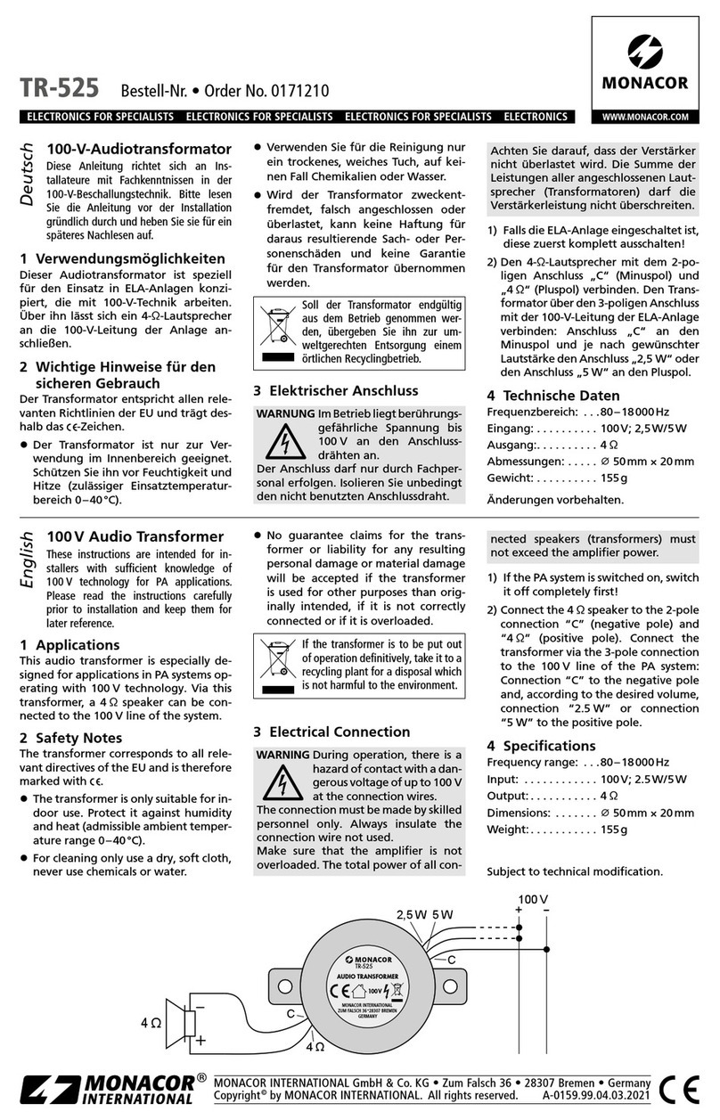
pro user INC150N User manual

1
P3
P16
P30
P34
P39
P44
P48
P52

2
Modified Sine Wave
1
1 2 3 4 5 1 8 7 6
2
5
4
3
2
1
6 7 9 8

3
Modified Sine Wave
Please read this instruction manual carefully before installing and starting up the
device, and store it in a safe place. If the device is passed on to another person, this
manual must also be handed over with it.
Contents
1. Notes on using the manual……………………………………………………………………4
2. Safety instructions………………………………………………………………………………4
3. Device guides……………………………………………………………………………………6
4. Technical description…………………………………………………………………………7
5. Connecting the inverter……………………… ………………………………………………8
6. Using the inverter…………… ………………………………………………………………10
7. Replacing the fuse……………………………………………………………………………12
8. Cleaning and caring for the inverter………………………………………………………12
9. Troubleshooting………………………………………………………………………………13
10.Guarantee………………………………………………………………………………………14
11.Disposal…………………………………………………………………………………………14
12.Technical date…………………………………………………………………………………15

4
Modified Sine Wave Noted on using the manual
1 Notes on using the manual
Caution
Safety instruction: Failure to observe this instruction can cause
material damage and impair the function of the device.
Caution
Safety instruction: relating to a danger from an electrical current or
voltage. Failure to observe this instruction can cause material damage and
personal injury and impair the function of the device.
Note
Supplementary information on operating the device
☞Action: This symbol indicates that action is required on your part. The required
action is described step-by-step.
√This symbol describes the result of an action.
Please observe the following safety instructions.
2 Safety instructions
2.1 Generalsafety
Caution
The manufacturer will not be held liable for claims for damage resulting from
the following:

5
ModifiedSineWave Safetyinstruction
―Faulty assembly or connection
―Damage to the appliance resulting from mechanical influences and excess voltage
―Alterations to the device without express permission from the manufacturer
―Use for purposes other than those described I the operating manual
―Use the device only as intended.
―Do not operate the device in a damp or wet environment.
―Maintenance and repair work may only be carried out by qualified personnel who are
familiar with the risk involved and the relevant regulations.
2.2 Safety when installing the device
● Ensure the device is standing firmly.
The device must be set up and fastened in such a way that it cannot tip over or fall down.
● Take the precautions necessary to ensure that children cannot interfere with operation.
Dangerous situations may occur which cannot be recognized by children!
● Do not expose the device to a heat source (such as direct sunlight or heating). Avoid
additional heating of the device in this way.
For installation on boats
● If electrical devices are incorrectly installed on boats, corrosion damage might occur.
Have the inverter installed by a specialist (marine) electrician.
Electrical cables
● If cables have to be fed through metal walls or other walls with sharp edges, use ducts or
wire bushings to prevent damage.
● Do not lay cables which are loose or bent next to electrically conductive material (metal).
● Do not pull on the cables.
● Do not lay the 230 V mains cable and the 12 V DC cable in the same duct.
● Fasten the cables securely.
● Lay the cables so that they cannot be tripped over or damaged.

6
ModifiedSineWave Safetyinstruction
2.3 Operating the appliance safely
Caution
Note the following basic safety information when using electrical devices to protect
against:
―Electric shock
―Fire hazards
―Injury
● Do not operate the advice near gas or flammable material; the surface temperature can
reach up to 65°C.
● Operate the device only if you are certain that the housing and the cables are
undamaged.
● Make sure the air inlets and outlets of the device are not covered.
● Ensure good ventilation.
● Do not connect the 230 V output of the inverter (fig. 1.2, page 2) to a different 230 V
source.
● Even after the fuse triggers, parts of the inverter remain live.
● Always disconnect the power supply when working on the device.
3 Device guides
Description Item No.
Modified sine wave INC150N: inverter in cup shape with USB socket and cable for 12V socket. INC150N
Modified sine wave INV150N: inverter with USB socket, and cable for 12V socket. INV150N
Modified sine wave INV300N: inverter with USB socket, and one cable for 12V socket, and two cables for 12V battery. INV300N
Modified sine wave INV600N: inverter with USB socket, and one cable for 12V socket, and two cables for 12V battery. INV600N
Modified sine wave INV1000N: inverter with USB socket, and two cables for 12V battery. INV1000N
Modified sine wave INV1500N: inverter with USB socket, and two cables for 12V battery. INV1500N
Modified sine wave INV2000N: inverter with USB socket and two cables for 12V battery. INV2000N

7
ModifiedSineWave Deviceguides
4 Technical description
The inverters are used to convert a direct current of 12V into a 230V AC supply of 50 HZ,
and/or 5V 2100mA USB.
The inverter can be operated wherever there is a 12V DC supply. The devices are
additionally cooled with a load fan.
The maximum constant output for the devices is as follows:
● For INC150N and INV150N inverters 150W
● For INV300N inverter 300W
● For INV600N inverter 600W
● For INV1000N inverter 1000W
● For INV1500N inverter 1500W
● For INV2000N inverter 2000W
Never connect devices that have a higher power requirement.
The inverter is equipped with protection against thermal and electrical over-loading, as well
as excess and insufficient voltage. The inverter alarms and switches off:
● if its internal temperature is too high
● if the load exceed the values stated above
● if the input voltage is too high or too low
The inverter can be switched on and off using the switch directly on the device.

8
ModifiedSineWave Technicaldescription
Note
Note when connecting devices with an electrical drive (such as power drills
and refrigerators), that they often require more power than the data is
indicated on the type plate.
5 Connecting the inverter
5.1 Fastening the inverter
You can fasten the inverters (INV300N, INV600N, INV100N0, INV1500N and INV2000N) by
screwing through the holes on the underside.
When selecting the installation location, observe the following instructions:
● The inverter can be mounted horizontally or vertically.
● The inverter must be installed in a place that is protected from moisture.
● The inverter may not be installed in the presence of flammable materials.
● The inverter may not be installed in a dusty environment.
● The place of installation must be well-ventilated. A ventilation system must be present for
installations in small, closed spaces. The minimum clearance around the inverter must
be at least 25 cm.
● The air intake on the front side or the air outlet on the back of the inverter must remain
clear.
● For ambient temperatures higher than 40°C (such as in engine or heating compartments,
or direct sunlight). The heat from the inverter under load can lead to the automatic
shut-off of the inverter.
● The installation surface must be level and sufficiently sturdy.
Caution
Before drilling any holes, ensure that no electrical cables or other parts of the
vehicle can be damaged by drilling, sawing and filing.

9
Modified Sine Wave Connecting the inverter
5.2 Connecting the inverter with car socket (INC150N, INV150N,
INV300N and INV600N)
The inverter is connected via a plug connected to a 12V socket. The middle pin of the plug
must be connected to the position wire and the two side brackets of the plug must be
connected to the negative wire.
Caution
Make sure the plug is firmly connected in the socket. If the connection is loose,
the plug may heat up.
Caution
The rating of the socket, the supply cable and the fuse must be at most 15amps. Do not
put in a fuse with a higher rating.
Caution
Always check the rated power of device before connecting with car socket. Its rated
power can NOT be more than 100W.
5.3 Connecting the inverter with battery (INV300N, INV600N,
INV1000N, INV1500N and INV2000N)
To set up the inverter, connect the red cable to the positive pole (+) of the battery and
inverter, connect the black cable to the negative pole (-) of the battery and inverter.
Caution
Make sure the battery poles are clean when connecting the terminals.
Tighten the nuts and bolts to a torque of 12-13 Nm. Loose connections may cause
overheating.

10
Modified Sine Wave Connecting the inverter
Caution
Do not reverse the polarity. Reversing the polarity of the connections will
cause a great spark and the internal fuses will melt.
Caution
Only extend the connection line with cables with and equal or greater cross
section.
Below cross section is for 100% copper wire, does not include thickness of
wire cover.
Device Required cable cross section Cable standard in AWG
100% copper wire (American wire gauge)
INV300N 3.00mm² 14#AWG
INV600N 5.30mm² 10#AWG
INV1000N 10.00mm² 8#AWG
INV1500N 16.00mm² 5#AWG
INV2000N 2x12.00mm² 2x7#AWG
6 Using the inverter
Switch on at the device
☞Set the main switch(fig. 1.4 page 2 ) to “ON”.
√The green LED (fig. 1.5 page 2) lights up.
Switch off at the device
☞Set the main switch(fig. 1.4 page 2 ) to “OFF”.
√The green LED (fig. 1.5 page 2) goes out.

11
ModifiedSineWave Usingtheinverter
Observe the following when using the device
If the battery voltage falls below 11V during operation, a warning tone sounds. If the battery
voltage falls further, the inverter switches off and the red error LED (fig. 1.5 page 2) lights up.
If the inverter overheats, it switches off – the red error LED lights up.
☞If this happens, switch the inverter off with the switch.
When it cools down, you can use the inverter again.
When operating the inverter at a high load for lengthy periods, it is advisable to start the
engine in order to recharge the vehicle battery.
You can operate the inverter with the engine running or switched off.
However, do not start the engine while the inverter is switched on, since the power supply to
the cigarette lighters is disconnected during ignition.
Caution
Modified sine wave inverter could operate with most electrical device. Please
check with the manufacturer of the product you are going to use if it is
possible. For example there might be problems operating with precise
instrument, e.g. high precision research testing equipment, medical monitor.
USB port
Connect the USB external appliance to the USB port and switch it on. The USB port on the
power inverter provides a power supply of 5V DC for external USB devices.
Warning
The USB port on the power inverter is not designed for transferring data. Do
not connect memory sticks, MP3 player or similar data storage external
appliances. Do not connect any data transfer cable to the USB port.

12
ModifiedSineWave Replacingthefuse
7 Replacing the fuse
This is how to change the fuse of the inverter
☞Take the defective fuse (fig. 2.7 page 2) out of the holder on the back.
☞Put in a new fuse of the same rating.
Note
For item INC150N, INV150N, INV300N, INV600N, always check the fuse in
cigarette plug first.
For item INV1000N, INV1500N, INV2000N, its fuse is inside of inverter.
Unscrew the 4 screws (fig. 2.9 page 2) to replace the fuses.
8 Cleaning and caring for the inverter
Caution
Do not use sharp or hard objects or cleaning agents for cleaning as these
may damage the device
☞Occasionally clean the device with a damp cloth.

13
ModifiedSineWave Troubleshooting
9 Troubleshooting
Fault Cause Remedy
No output voltage No contact to the battery Check contact and cable. Switch On the ignition if
necessary.
INC150N/ INV150N/ INV300N/ INV600N: check the 12V
socket and replace it if necessary.
Overheating Switch off power consuming devices
Let the inverter cool down and ensure better ventilation.
Defective fuse (in the
Cigarette plug, inverter, or
The vehicle)
Replacing the fuse with one of the same specification.
Device defective Replace the device.
Interference From TV set/audio
systems and / or other
external appliances
operation
snow image, image not
steady
humming, booming and
whirring sound audible.
Place power inverter as far away from TV set as possible,
check aerial connection and setting. Place aerial cable
away from power inverter. Use a shielded aerial cable.
The modified sine wave of the power inverter cannot be
filtered sufficiently by the connected external appliance.
disconnect all cables immediately. The only available
solution is to use a more modern external appliance or
one with a higher rating with adequate filtering capability.
The device
switches On and
off repeatedly
Excessive constant load Reduce the load.

14
ModifiedSineWave Troubleshooting
10 Guarantee
The statutory warranty period applied. If the product is defective, please discuss further
steps with the dealer where you have bought the device
11 Disposal
☞If possible, always take the packing material for recycling.
If you wish to finally dispose of the device, ask your local recycling center or
specialist dealer for details about how to do this in accordance with the
applicable disposal regulations.

15
ModifiedSineWave Technicaldata
12 Technical data
Item no: INC150N
INV150N INV300N INV600N INV1000N INV1500N INV2000N
Output power: 150W 300W 600W 1000W 1500W 2000W
Fuse in cigarette plug -- 15Ax1 15Ax1 -- -- --
Spade-type fuse 15Ax1 20Ax2 20Ax4 20Ax6 30Ax6 25Ax10
Wave form
Modified Sine wave
Rated input voltage DC 12V
Input voltage range 11V – 15V
output AC 230V +/- 10%
output frequency
range 50 +/- 2HZ
USB output 5V 2100mA
Ambient temperature
for operation 0℃-40℃
Ambient temperature
for storage -30℃– 70℃
Efficiency up to 90%
High voltage shutdown Shutdown: 15-16v
Low voltage shutdown
warning: 10.5-11.0V
shutdown: 10V-11V
Automatic restart: 12V +- 1V
High temperature
shutdown
Internal temperature
Shutdown at 70℃+-5℃
Cooling element
Shutdown at 90℃

16
Wechselrichter Inhaltsverzeichnis
Bitte lesen Sie diese Anleitung vor Einbau und Inbetriebnahme sorgfältig und
bewahren Sie sie auf. Geben Sie sie im Falle einer Weiterveräußerung des Geräts an
den Käufer weiter.
Inhaltsverzeichnis
1. Hinweise zur Benutzung der Anleitung……………………………………………………17
2. Allgemeine Sicherheitshinweise …………………………………………………………17
3. Bestimmungsgem er Gebrauch ……………………………………………………………19
4. Technische Beschreibung …………………………………………………………………20
5. Wechselrichter anschließen…………………………………………………………………21
6. Wechselrichter benutzen ……………………………………………………………………24
7. Sicherung wechseln …………………………………………………………………………25
8. Wechselrichter pflegen und reinigen ……………………………………………………26
9. Fehlerbeseitigung ……………………………………………………………………………27
10.Gewährleistung ………………………………………………………………………………28
11.Entsorgung ……………………………………………………………………………………28
12.Technische Daten ……………………………………………………………………………29

17
Wechselrichter Hinweise zur Benutzung der Anleitung
1 Hinweise zur Benutzung der Anleitung
Achtung !
Sicherheitshinweise: Nichtbeachtung kann zu Materialschäden führen und die Funktion
des Gerätes beeinträchtigen.
Achtung !
Sicherheitshinweis, der auf Gefahren mit elektrischem Strom oder elektrischer
Spannung hinweist. Nichtbeachtung kann zu Personen- und Materialschäden führen und
die Funktion des Gerätes beeinträchtigen.
Hinweis
Ergänzende Informationen zur Bedienung des Gerätes.
☞Aktion: Dieses Symbol zeigt Ihnen, dass Sie etwas tun müssen. Die erforderlichen
Handlungen werden Schritt für Schritt beschrieben.
√Dieses Symbol beschreibt das Ergebnis einer Handlung.
Beachten Sie bitte auch die nachfolgenden Sicherheitshinweise.
2 Allgemeine Sicherheitshinweise
2.1 Allgemeine Sicherheit
Achtung
Der Hersteller übernimmt keine Haftung für Schäden aufgrund folgender
Punkte:

18
Wechselrichter AllgemeineSicherheitshinweise
―Montage- oder Anschlussfehler
―Beschädigungen am Gerät durch mechanische Einflüsse und Überspannungen
―Veränderungen am Gerät ohne ausdrückliche Genehmigung des Herstellers
―Benutzen Sie das Gerät nur zu seinem bestimmungsgemäßen Gebrauch.
―Betreiben Sie das Gerät nicht in feuchter oder nasser Umgebung
―Die Wartung und Reparatur darf nur durch eine Fachkraft geschehen, die mit den damit
verbundenen Gefahren bzw. einschlägigen Vorschriften vertraut ist.
2.2 Sicherheit bei der Installation des Gerätes
● Achten Sie auf einen sicheren Stand! Das Gerät muss so sicher aufgestellt und befestigt
werden, dass es nicht umstürzen oder herabfallen kann.
● Sichern Sie das Gerät so, dass Kinder keinen Zugriff darauf haben. Es können Gefahren
entstehen, die von Kindern nicht erkannt werden.
● Setzen Sie das Gerät keiner Wärmequelle (Sonneneinstrahlung, Heizung, usw.) aus.
Vermeiden Sie so zusätzliche Erwärmung des Gerätes.
BeiderInstallationaufBooten
● Bei falscher Installation elektrischer Geräte auf Booten kann es zu Korrosionsschäden
am Boot kommen. Lassen Sie die Installation des Wechselrichters von einem
fachkundigen Elektriker durchführen.
Elektrische Leitungen:
● Müssen Leitungen durch Blechwände oder andere scharfkantige Wände geführt werden,
dann benutzen Sie Leerrohre bzw. Leitungsdurchführungen.
● Verlegen Sie Leitungen nicht lose oder scharf abgeknickt an elektrisch leitenden
Materialien (Metall).
● Ziehen Sie nicht an Leitungen.
● Verlegen Sie 230-V—Netzleitung und 12V-V-Gleichstromleitung nicht zusammen im
gleichen Leitungskanal (Leerrohr).
● Befestigen Sie die Leitungen gut.
● Verlegen Sie die Leitungen so, dass keine Stolpergefahr entsteht und eine
Beschädigung des Kabels ausgeschlossen ist.

19
Wechselrichter Geräteausführungen
2.3 Sicherheit beim Betrieb des Gerätes
Achtung!
Beachten Sie folgende grundsätzliche Sicherheitsmaßnahmen beim Gebrauch von
elektrischen Geräten zu Schutz vor:
―elektrischem Schlag
―Brandgefahr
―Verletzungen
● Betreiben Sie das Gerät nicht in der Nähe von Gas oder entflammbaren Materialien; die
Oberflächentemperatur kann bis zu 65° C betragen.
● Betreiben Sie das Gerät nur, wenn das Gehäuse und die Leitungen unbeschädigt sind.
● Achten Sie darauf, dass Luftein- und Ausgänge des Geräts nicht verdeckt werden.
● Achten Sie auf gute Belüftung.
● Verbinden Sie den 230-V-Ausgang des Wechselrichters (siehe Abb.) nicht mit einer
anderen 230-V-Quelle.
● Auch nach Auslösen der Schutzeinrichtung (Sicherung) bleiben Teile des
Wechselrichters unter Spannung.
● Unterbrechen Sie bei Arbeiten am Gerät immer die Stromversorgung.
3 Geräteausführungen
INC150N: Wechselrichter mit modifizierter Sinuswelle in Dosenform und mit USB und Kabel für 12V Zigarettenanzünder.
INV150N: Wechselrichter mit modifizierter Sinuswelle mit USB und Kabel für 12V Zigarettenanzünder.
INV300N: Wechselrichter mit USB, Kabel für 12V Zigarettenanzünder und zwei Kabel für Anschluss an 12V Batterie.
INV600N: Wechselrichter mit USB, Kabel für 12V Zigarettenanzünder und zwei Kabel für Anschluss an 12V Batterie.
INV1000N: Wechselrichter mit modifizierter Sinuswelle mit USB und zwei Kabel für Anschluss an 12V Batterie.
INV1500N: Wechselrichter mit modifizierter Sinuswelle mit USB und zwei Kabel für Anschluss an 12V Batterie.
INV2000N: Wechselrichter mit modifizierter Sinuswelle mit USB und zwei Kabel für Anschluss an 12V Batterie.

20
Wechselrichter TechnischeBeschreibung
4 Technische Beschreibung
Die Wechselrichter dienen dazu, Gleichspannung von 12V in eine 230V-Wechselspannung
von 50Hz zu wandeln und/oder in 5V mit 2100mA Spannung beim USB Anschluss. Die
Wechselrichter können überall dort betrieben werden, wo ein 12-V-DC-Anschluss
vorhanden ist. Die Geräte werden mit einem Lüfter bei Bedarf zusätzlich automatisch
gekühlt.
Die maximale Dauerleistung beträgt:
● Für INC150N und INV150N > 150W
● Für INV300N > 300W
● Für INV600N > 600W
● Für INV1000N > 1000W
● Für INV1500N > 1500W
● Für INV2000N > 2000W
Geräte, die einen höheren Leistungsbedarf haben, dürfen nicht angeschlossen werden.
Der Wechselrichter ist mit einem thermischen und einem elektrischen Überlastungsschutz
sowie einem Unter- und Überspannungsschutz ausgestattet. Der Wechselrichter schaltet
ab:
● Wenn die interne Temperatur des Wechselrichters zu hoch ist
● Wenn die Belastung die oben genannte Leistungswerte übersteigt
● Wenn die Eingangsspannung zu niedrig oder zu hoch ist
Die Wechselrichter können alternative über den Schalter direkt am Gerät oder über einen
externen Schalter ein- und ausgeschaltet werden.
This manual suits for next models
6
Table of contents
Popular Transformer manuals by other brands
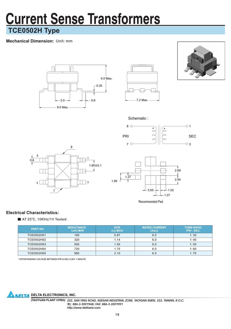
Delta Electronics
Delta Electronics Current Sense Transformers TCE0502H Specification sheet
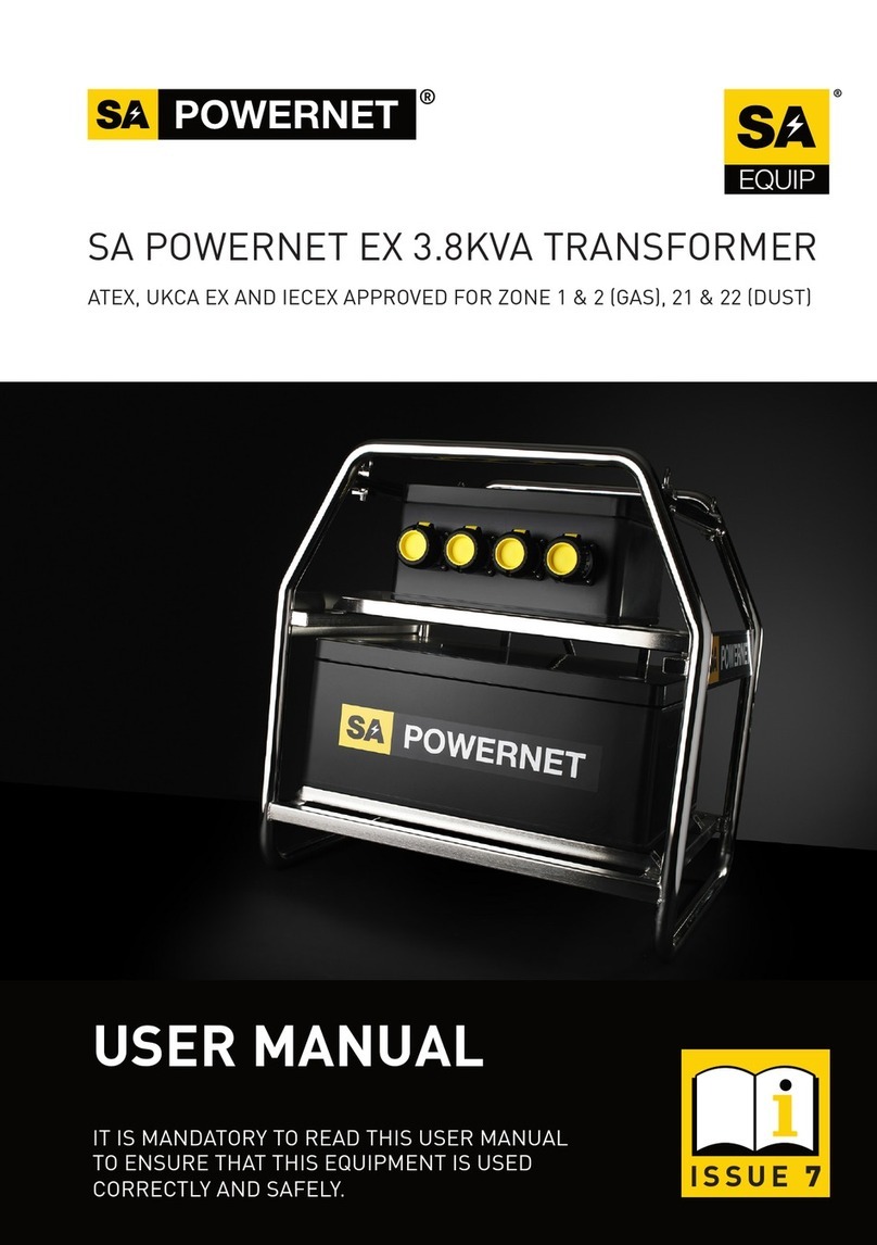
SA
SA POWERNET PNLT230110 user manual
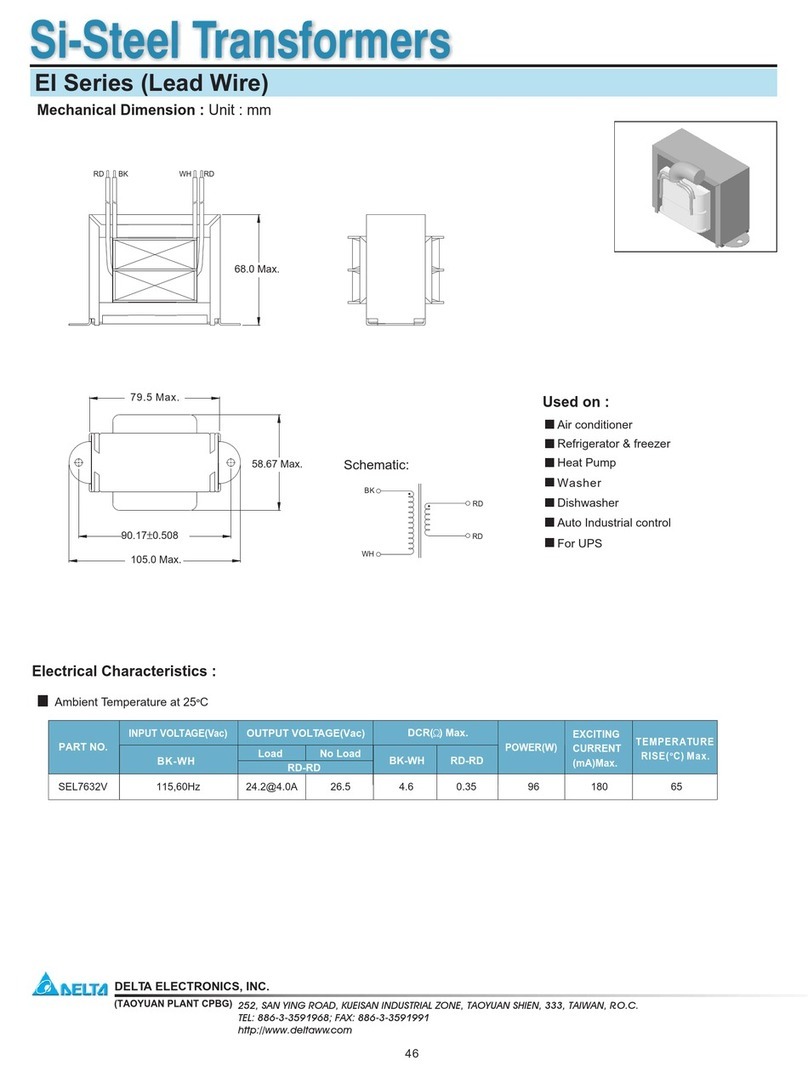
Delta Electronics
Delta Electronics SEL7632V Specification sheet
Robus
Robus LDT150N instructions

ABBA
ABBA STS150 installation guide
JUNO
JUNO TL575-xx-277-BL Series installation instructions
