ProAir FGP Series User manual

Manual
Hardware and Software
FGP_e // V1.0 // technical data are subject to change //350125
Thermal
Mass flow meter
for COMPRESSED AIR and GASES
Model FGP
FGP-3
flowguardPRO - flex
FGP-4
flowguardPRO - 4...20
FGP-1 and FGP-2
flowguardPRO - compact

2
We doesn't accept warranty and liability claims neither upon this pub-
lication nor in case of improper treatment of the described products.
The document may contain technical inaccuracies and typographical
errors. The content will be revised on a regular basis. These changes
will be implemented in later versions. The described products can be
improved and changed at any time without prior notice.
© Copyright
All rights reserved.
USA
FCC notice:
This equipment has been tested and found to comply with the limits for a Class B
digital device, pursuant to part 15 of the FCC Rules. These limits are designed to
provide reasonable protection against harmful interference in a residential installa-
tion. This equipment generates, uses and can radiate radio frequency energy and,
if not installed and used in accordance with the installation manual, may cause
harmful interference to radio communications. However, there is no guarantee that
interference will not occur in a particular installation. If this equipment does cause
harmful interference to radio or television reception, which can be determined by
turning the equipment off and on, the user is encouraged to try to correct the
interference by one or more of the following measures:
- Reorient or relocate the receiving antenna.
- Increase the separation between the equipment and receiver.
- Connect the equipment into an outlet on a circuit different from that to which the
receiver is connected.
- Consult the dealer or an experienced radio/TV technician for help.
Caution:
Any changes or modifications not expressly approved by the party responsible for
compliance could void the user's authority to operate this device.
CANADIAN
ICES-003 notification:
This Device B digital apparatus complies with Canadian ICES-003.
Cet appareil numérique de la classe B est conforme à la norme NMB-003 du
Canada.

3
1. GENERAL ............................................................................................................ 4
1.1.Symbol Clarification ................................................................................................. 4
1.2.Safety Instructions .................................................................................................. 4
1.2.1. Intended Use ................................................................................................... 4
1.2.2. Installation, start up and control .................................................................................. 5
1.3.Environmental aspects.............................................................................................. 5
2. PRODUCT DESCRIPTION....................................................................................... 6
3. INSTALLATION...................................................................................................... 7
3.1.Mounting dimensions ............................................................................................... 7
3.1.1. FGP-1, FGP-2 and FGP-3 ....................................................................................... 7
3.1.2. FGP-4 ......................................................................................................... 8
3.2.Determining installation site......................................................................................... 8
3.2.1. Process pressure ............................................................................................... 8
3.3.Installation position.................................................................................................. 9
3.4.Required length of straight pipe..................................................................................... 10
3.5.Installation FGP-1, FGP-2 and FGP-3 .............................................................................. 11
3.5.1. Mounting valve - ball valve....................................................................................... 11
3.5.2. Assembly without flowmeter, but with screw cap instead (blind cap) ................................................. 11
3.5.3. Shut off the ball valve ........................................................................................... 11
3.5.4. Installation of the flowmeter sensing probe ........................................................................ 12
3.5.5. Removal of the sensing probe of the flowmeter.................................................................... 12
3.6.Installation FGP-4 in the pipe line .................................................................................. 13
3.7.Setting the pipe diameter ........................................................................................... 15
4. ELECTRICAL CONNECTIONS ................................................................................. 16
4.1.Connection diagram................................................................................................. 16
4.1.1. Relay and pulse output, internal switching ........................................................................ 16
5. CONTROL COMPONENTS ...................................................................................... 17
5.1.Jumper J1 and J2 ................................................................................................... 17
5.2.Digital interface USB ( for configuration)............................................................................ 17
5.3.Display / Indicator with keypad (optional)........................................................................... 18
5.3.1. Indication of the analogue and pulse output ....................................................................... 18
5.3.2. Indication of the switch output.................................................................................... 18
5.3.3. Indication of the MIN / MAX values ............................................................................... 19
5.3.4. Reset of the consumption counter or the MIN / MAX value ......................................................... 19
6. ERROR MESSAGES .............................................................................................. 20
7. MAINTENANCE ..................................................................................................... 20
7.1.Cleaning of the sensor of the flowmeter ............................................................................ 20
8. REPLACEMENT PARTS / ACCESSORIES ................................................................. 20
8.1.Order Code Replacement Sensor .................................................................................. 20
8.2.Order Code Replacement sensor cable (only for FGP-3 and FGP-4) ...................................... 21
8.3.Order Code Replacement mounting valve for FGP-1, FGP-2 und FGP-3 ......................................... 21
8.4.Order Code Accessories for FGP-4................................................................................. 21
9. TECHNICAL DATA FGP-1, FGP-2 and FGP-3............................................................. 22
10.TECHNICAL DATA FGP-4....................................................................................... 24
Table of contents - HARDWARE
Table of contents - SOFTWARE
1. General ................................................................................................................ 26
2. Installation ........................................................................................................... 26
2.1.Configuration of the USB Interface (VirtualCOM)................................................................... 27
3. User Interface ....................................................................................................... 28
4. Menu toolbar ........................................................................................................ 28
4.1.File .................................................................................................................. 28
4.2.Transmitter .......................................................................................................... 29
4.3.Extras ............................................................................................................... 29
5. Input Screen......................................................................................................... 29
5.1.Output 1, Output 2 .................................................................................................. 29
5.1.1. Output mode ................................................................................................... 29
5.1.2. Measurand ..................................................................................................... 29
5.1.3. Units........................................................................................................... 29
5.1.4. Output mode – analogue ........................................................................................ 29
5.1.5. Output mode – switch (relay) .................................................................................... 30
5.1.6. Output mode – pulse ............................................................................................ 31
5.2.Display .............................................................................................................. 31
5.3.Adjustment .......................................................................................................... 32
5.3.1. 1-point adjustment .............................................................................................. 32
5.3.2. 2-point adjustment .............................................................................................. 33
5.3.3. Reset to factory settings ......................................................................................... 33
5.4.Measuring values overview ......................................................................................... 34
5.4.1. Reset of the MIN / MAX values .................................................................................. 34
5.4.2. Reset of the consumption counter (totalizer)....................................................................... 34
5.5.Setting up Process Parameters..................................................................................... 34
5.5.1. Change the Process Gas ........................................................................................ 34
5.5.2. Pressure compensation ......................................................................................... 35
5.5.3. Setting the pipe diameter ........................................................................................ 35
5.6.External pressure transmitter for pressure compensation .......................................................... 35

4
1. GENERAL
This manual is a part of the scope of supply and serves to ensure optimal operation and functioning of the
equipment.
For this reason, the manual must be read before start-up.
Therefore, it is necessary that this manual is read and understood by those responsible for the handling,
installation, and maintenance of the equipment.
This manual may not be used for competitive purposes or passed on to third parties
without the written consent.
It is permitted to make copies for personal use.
All information, technical data and illustrations contained in these instructions are based on
information available at the time of publication.
1.1. Symbol Clarification
This symbol indicates safety instructions.
The safety instructions have to be carried out unconditionally. If disregarded loss, injury, or damage may be
inflicted to people and property. In any case we cannot be hold responsible.
This symbol indicates attention.
The note should be observed to achieve an optimal functioning of the equipment.
1.2. Safety Instructions
1.2.1. Intended Use
The flowmeter is intended to be used for the measurement of air and other non-corrosive gasses in pipelines
only. Consult the factory first before the measurement of wet or filthy gasses.
The design of the flowmeter allows for the FGP to be installed in a pressurized system up to PN16 – is
16 bar (230 psi).
For FGP-1, FGP-2 and FGP-3:
Prior to the start of the installation, the system has to be depressurized. Before the installation or
removal of the sensing probe or the screw cap, the ball valve should be closed.
Mounting, electrical installation, putting in operation and maintenance should only be done by qualified
personnel.
The use of the flowmeter in any other way than described in this manual bears a safety risk for people and
the entire measurement installation and is therefore not allowed.
The manufacturer cannot be hold responsible for damages as a result of incorrect handling, installation, and
maintenance of the equipment.
To avoid health risks or damage to the equipment, the installation should not be operated on with tools, which
are not specifically mentioned or described in this manual.
Excessive mechanical stress and inappropriate handling must be avoided.
For FGP-1, FGP-2 and FGP-3:
A short interruption of the flow using the ball valve cannot be avoided when exchanging the sensing probe.
The flowmeter can only be utilized in accordance with the conditions defined in the technical data. Otherwise,
inaccuracies of the measurement will occur and equipment failures cannot be ruled out.
For the safety of the user and for the functionality of the equipment the recommended steps by the
manufacturer to put into operation, to test and to maintain should be taken and completed.

5
1.2.2. Installation, start up and control
The flowmeter is designed and built in accordance with the latest state in technology, tested adequately and
has been shipped from the factory in good order and condition.
As the user, you are responsible to comply with all applicable safety regulations amongst others:
• Instruction for the installation
• Local standards and codes
The manufacturer has taken all measures to assure safe operation. The user has to make sure that the
equipment is positioned and installed in such a way that safe operation is not impaired.
The equipment is tested in the factory and shipped in good order and condition.
This manual contains information and notes of caution, which have to be adhered to by the user to assure a
safe operation.
• Mounting, electrical installation, putting into operation and maintenance should only be done by
qualified personnel. The plant operator should authorize qualified personnel to operate on the
installation.
• It is necessary that this manual is read and understood by these professionals and that they follow
the instructions as detailed in this manual.
• Check all connections of the entire installation thoroughly, before putting the system into operation.
• Do not put a damaged product into operation and make sure that that does not happen inadvert-
ently.
• A malfunction of the equipment should only be handled and fixed by authorized and qualified
personnel
• If it is not possible to repair the malfunction, put the equipment out of operation and make sure that
it cannot be put back into operation again.
• Repairs not described in this manual may only be carried out by the manufacturer or by the
respective service organization.
Disclaimer of Liability
The manufacturer or their delegated representative is only liable in case of intend or gross negligence. The
accountability is limited to the value of the order issued at the time to the manufacturer.
The manufacturer is not liable for damages, originated from disregarding the safety instructions or violating
the instructions of the manual or operating conditions.
Consequential damages are excluded from the any liability.
1.3. Environmental aspects
The products are developed and designed in due consideration to the importance of the protection of the
environment. Therefore, disposal of the product also should not lead to pollution of the
environment.
The single-variety components must be separated before the transmitter is disposed of. The electronic
components must be collected and as electronic scrap properly be disposed of.

6
2. PRODUCT DESCRIPTION
The flowmeter of the series FGP, based on the measurement principle of thermal mass flow, is suited for the
measurement of flow of air and gasses in pipelines. Measurement of for instance the consumption of com-
pressed air, nitrogen, helium, CO2, oxygen or other non-corrosive and non-flammable gasses.
The FGP measures the volume flow at standard conditions according to DIN 1343 (P0 = 1023.25 mbar; t0 =
273.15 K or 0 °C (32 °F). In addition to the standard volume flow, the measurand mass flow, norm flow and
temperature are available.
The FGP has an integrated consumption counter. The consumption quantity is indicated in the display and is
not lost after a power failure. Two signal outputs are available. Depending on the application, the outputs can
be configured as analogue (current or voltage), switch output or as pulse output for the measurement of the
consumption.
Mounting valve - Ball valve
The mounting valve assembly allows for the easy and reliable instal-
lation within the pipeline. During installation in the pipeline, observe
the required inlet and outlet paths (see page 10). The nominal size of
the ball valve assembly must match the nominal size of the pipe.
The ball valve allows for the instalment and removal of the sensing
probe with only interrupting the process flow for a short moment. The
ball valve assembly is suitable for pressures up to 16 bar (PN16) and
available for pipe diameters DN15 (1/2”) to DN50 (2”).
Signal conditioning with optional display
The enclosure with the signal conditioning is mounted either on the
measurement probe (model 1 or 2 compact) or is remote with a plu-
gable sensor cable up to 10 meter (33 feet) – (model 3 with remote
probe).
Sensing probe with measurement electronics
The interchangeable sensing probe contains the sensor element and
the measurement electronics, in which the data of the factory calibra-
tion is stored. The sensing probe is easy and quickly interchangeable
intheeld,independentoftheelectronicsforthesignalconditioning.
Aftertheexchange,thecongurationoftheoutputsisunchanged.
Screw cap
The screw cap, with female thread, is screwed in place if the flowm-
eter is not installed and the pipeline has to be used.
Sensor cable (only by model 3 with remote sensing probe)
The sensor cable allows for the remote installation, up to 10 meter (33
feet), of the sensing probe from the housing with the signal condition-
ing.
1
5
3
4
2
1
2
3
5
4
FGP-1, FGP-2 and FGP-3
FGP-4
1
236
7

7
3. INSTALLATION
3.1. Mounting dimensions
3.1.1. FGP-1, FGP-2 and FGP-3
115 145
129
BA
60
183
173
56
60
40
cable gland
M16x1.5
cable gland
M16x1.5
Cross-section
bore hole:
Drilling Plan:
The bottom part of the housing is mounted with
4 screws (not in the scope of supply)
Max. screw diameter: 4.5 mm (0.17 inch).
e.g. 4.2 x 38 mm DIN 7938H Screws
Ball valve Threat A B
DN15 Rp1/2" 83,7 35
DN20 Rp3/4" 72,7 35
DN25 Rp1" 88 47.5
DN32 Rp1 1/4" 100 120
DN40 Rp1 1/2" 110 120
DN50 Rp2" 131 120
Female thread:
BSP thread acc. EN 10226
(old DIN 2999)
Mounting valve - Ball valve
Dimensions in mm
Non-return protection for secure mounting
The patented non-return protection combines three functions in one device:
• Non-return protection
The sensor can only be pushed in one direction during installation. The sensor cannot return at all,
even if it is released.
• Seal
By means of an encapsulated O-ring, no compressed air can escape under pressure during assem-
bly.
• Precise positioning
The precise positioning with respect to immersion depth and orientation is easy to perform, guaran-
teeing accurate measurement results.
Mounting grip
With the mounting grip, the sensing probe is inserted and correctly positioned into the pipe line.
7
6

8
3.2. Determining installation site
• The installation site should be easy accessible and free of vibrations and shocks
• Observe enough clearance above the mounting position, in order to be able to install and remove
the sensing probe:
at least 120 mm (4.72) for FGP-1, FGP-2 and FGP-3
at least 450 mm (17.7”) for FGP-4 probe length 285 mm (11.22”) DN65 (2 1/2”) up to DN100 (4”)
at least 600 mm (23.6”) for FGP-4 probe length 435 mm (17.13”) DN125 (5”) up to DN300 (12”)
• The ambient temperature should not exceed the value as stated in the specifications (see page
22) – consider heating by radiation.
• The fluid should not condense at the installation site. Condensation on the tip of the sensing probe
must be avoided.
• In compressed air systems, the installation should be downstream of the dryer.
• Observe the direction of the flow by the installation (see page 11).
• Observe the required straight pipe lengths up and downstream, in order to warrant the specified
measurement accuracy.
• The flowmeter should be installed as far as possible from any flow disturbance. Valves or check-
valves should be installed in a respective distance from the flowmeter.
3.2.1. Process pressure
Because of the measuring principle the thermal mass flowmeter FGP is largely independent of the process
pressure and is factory calibrated at a pressure of 7 bar (100 psi) (FGP-1, FGP-2 and FGP-3) or 9 bar (130.5
psi) (FGP-4).
In order to achieve the highest measurement accuracy, the slight dependence on process pressure can be
compensated for in two ways:
• if the process pressure is stable, by programming the pressure value in the configuration software
(see page 35).
• in case of strong fluctuations of the process pressure (e.g. 3 to 10 bar (40 to 150 psi)) an external
pressure transmitter can be installed and connected to the pressure-compensation input
(see page 35).
R 1/2“ thread
M12x1 Connector
for probe cable
285 (11.22“) or 435 (17.13“)
variable insertion depth
max. 165 (6.5“) or 315 (12.4“)
45 (1.77“)
38 (1.5“)
20 (0.79“)
15
(0.59“)
12
(0.47“)
120 (4.72“)
180 (7.09“)
Ø 40 (1.57“)
Ø 13 (0.51“)
Ø 14 (0.55“)
Ø 40 (1.57“)
SW 36 (1.42“)
see accessories for NPT adapter
3.1.2. FGP-4

9
Model
Vertical Mounting Compact Remote
+ ++
Horizontal Mounting, sensor upwards
++ ++
Horizontal Mounting, sensor downwards
- -
Horizontal Mounting, sensor across
+ ++
3.3. Installation position
Make sure that the arrow on the tip of the sensing probe is pointing in the direction of the flow.
++ ... recommended installation position
+ ..... not recommended if there is vibration on the pipeline
-....... not recommended
10
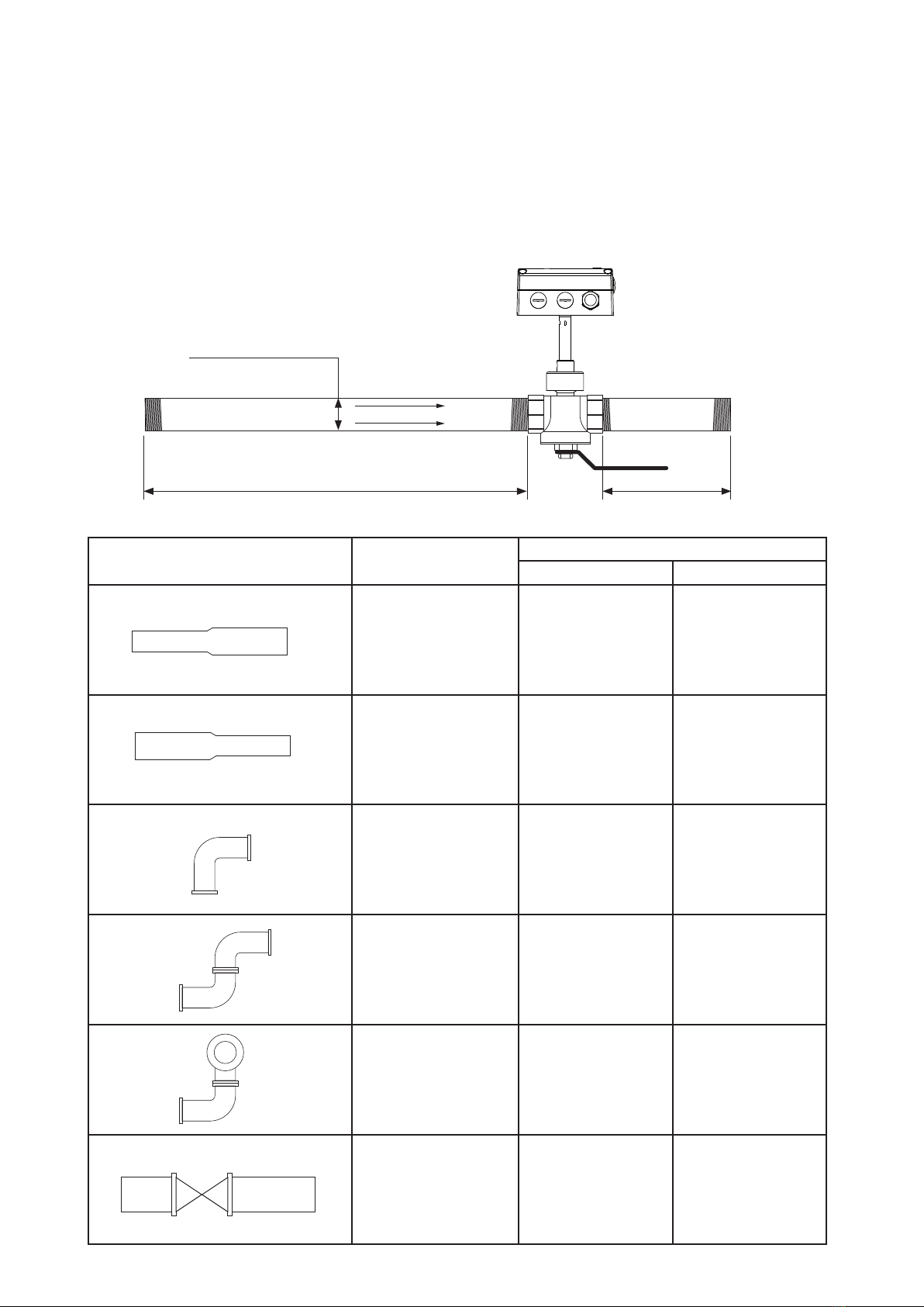
Type
(DN = Nominal Pipe Size)
Straight inlet pipe Straight outlet pipe
Extension 15 x DN 5 x DN
Reduction 15 x DN 5 x DN
90° - elbow 20 x DN 5 x DN
Two 90° - elbows,
in one level 25 x DN 5 x DN
Two 90° - elbows,
in two levels 30 x DN 5 x DN
Valve, gate valve 50 x DN 5 x DN
3.4. Required length of straight pipe
The flowmeter should be installed as far as possible from disturbances of the flow. The causes for disturbance
of the flow are for instance, reducers, elbows, T-pieces, valves, gate valves, etc. The specified measurement
accuracy can be achieved only when the following straight inlet and outlet pipe lengths are installed:
• The stated values are as a minimum. If possible, allow for greater distances.
• Valves or gate valves should be installed downstream of the flowmeter.
• With lighter gasses the inlet straight pipe should be longer.
• Only for FGP-1, FGP-2 and FGP-3: The wall thickness of the inlet and outlet pipe should be 2,6 mm
owdirection
straight inlet pipe
nominal pipe size (DN)
straight outlet pipe

11
3.5. Installation FGP-1, FGP-2 and FGP-3
3.5.1. Mounting valve - ball valve
• all connections to be made with appropriated sealing material on the threads.
• the sealing material should not change the area of the inner cross section of the pipe. It must be
warranted that the connections after installation are free of leaks.
• All fittings must be tested on seal tightness.
• Observe the required length of inlet and outlet pipe section.
• The recess for the alignment pin must be at the side of the outlet.
recess for
alignment pin
Flow Direction
3.5.2. Assembly without flowmeter, but with screw cap instead (blind cap)
In order to use the measurement section without the flowmeter, the blind screw cap (in
the scope of supply) must be screwed tight onto the opening of the ball valve. If not
needed the screw cap can be screwed and stored on the handle of the ball valve.
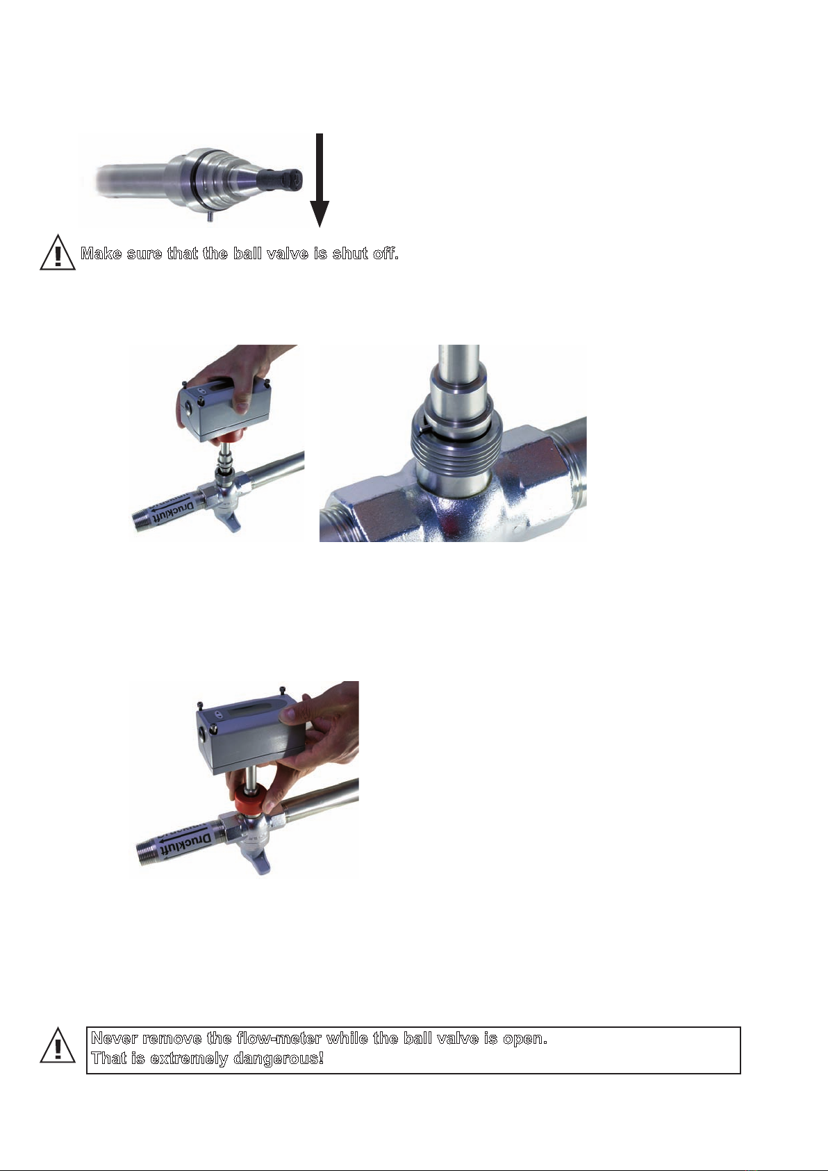
3.5.3. Shut off the ball valve
The ball valve assembly allows for the installation and removal of the flowmeter within seconds, with only a
very short interruption of the flow.
OPEN CLOSED
Never remove the flowmeter
or the blind screw cap while
the ball valve is open.
That is extremely danger-
ous!
12
Make sure that the ball valve is shut off.
• Remove transport protection cap of the head of the sensing probe.
• Mount the sensing probe in the ball valve in such a way that the alignment pin fits in the recess on
the ball valve.
• Screw the retainer nut by hand so far that a certain resistance is noticeable.
• Check the correct installation position of the flowmeter. The alignment pin must fit in the recess on
the ball valve.
• Tighten the red coloured retainer nut by hand. Tightening by hand should be sufficient. However, if
the seal is not leak tight carefully tighten the nut with an appropriate tool a bit further.
• The mechanical installation of the flowmeter is therewith completed.
Flow Direction
3.5.4. Installation of the flowmeter sensing probe
The flow direction is indicated with an arrow on the tip of the probe. Due to the alignment pin is the installation
of the sensing probe in the ball valve only possible in the direction of the flow. After a removal, the sensing
probe will be re-installed in the measurement section in exactly the same position as done at the factory.
Hence, the highest reproducibility is guaranteed.
3.5.5. Removal of the sensing probe of the flowmeter
• Shut off the ball valve (see page 11).
• Turn off the power supply, remove the cover and disconnect the power wires on the screw terminal.
• Loose the retainer nut and pull the sensor probe from the measurement section.
• Operation without the flowmeter installed page 11.
Never remove the flow-meter while the ball valve is open.
That is extremely dangerous!

13
3.6. Installation FGP-4 in the pipe line
The patented non-return protection device for reliable installation combines three functions in one unit:
• Non-return protection device
The sensor can only be pushed in one direction during installation. The sensor will not move back at all,
even when it is released.
• Seal
Thanks to an encapsulated O-ring, no compressed air can escape under pressure during assembly.
• Precise positioning
The precise positioning with respect to immersion depth and orientation is easy to perform, guarantee-
ing accurate measurement results.
An example installation is described below using the weld-on nipple in combination with the 1/2“ ball valve.
The same basic principles apply to installation with the tapping sleeve.
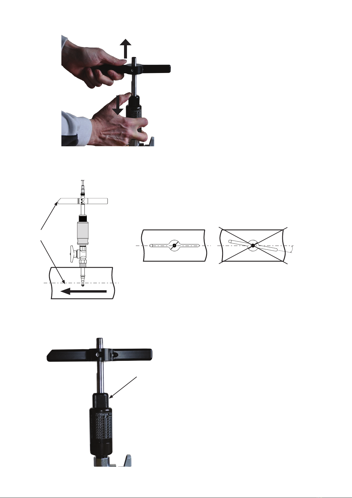
• Pull the measurement sensor back into the non-return protection device as far as it will go.
• Screw the non-return protection device into the ball valve using suitable sealants for a fully sealed
connection.
• Screw knurled nut in by approx. one thread turn.
Knurled nut
• Open the ball valve and dip the measurement sensor into the pipe line.
• Positioning in the pipe line
To ensure that the accuracy level specified on the data sheet is observed, the sensor head must
be positioned in the centre of the pipe. The scale on the sensor pipe for the immersion depth
relates to the centre of the sensor head.
ED
12
0,5 * ED
0,5 * ED
ED
X
Immersion depth = x +
ED... External diameter
ED
2
Correct position in the pipe line
14
• If the measurement sensor is immersed too far into the pipe line, it can be retracted by unlocking
the non-return protection device. To do this, slowly press the knurled nut inwards. As with a pres-
sure point in a car clutch, this permits the immersion
depth to be set to the precise millimetre.
• Align the measurement sensor with the flow direction.
The flowmeter has a set flow direction. Ensure that the direction arrow on the sensor head or the
mark on the mounting handle is pointing in the media flow direction.
The measurement sensor is aligned with precision in the flow direction using the mounting handle.
An angle deviation must not be greater than ±5° from the ideal posi-
tion.
Flow direction
CORRECT INCORRECT
Mark for flow
direction
>5°
Align the mounting grip
parallel to the pipe
• When the measurement sensor is correctly positioned in terms of immersion depth and alignment,
tighten the knurled nut by hand.
Knurled nut

15
• Connect the measurement sensor and the evaluation unit to the sensor cable.
Sensor cable
Sensor cable
3.7. Setting the pipe diameter
The flowmeter is factory-set so that the average corrected flow speed is measured in the pipe. The standardized
volumetric flow is calculated by the flowmeter as follows:
V0= v0* id2*π/4*3600
V0...Standardizedvolumetricow[m3/h]
v0...Standardizedow[m/s]
id...Internaldiameterofpipe[m]
π...3,1415
The internal diameter is factory-set to 56.3 mm (2,22”). For the correct volume flow/mass flow to be calculated
correctly, the actual internal diameter of the pipe where the measurement is being made, must be set using
the configurator software! (see page 35)

16
4. ELECTRICAL CONNECTIONS
Before electrical connections are made turn off the power supply first. If not observed the electronics can be
damaged as a result.
Only a qualified electrotechnical engineer may install the device.
• Unscrew the four screws and remove the cover of the housing.
• The screw terminals are located in the bottom part of the housing.
• For the electrical connection of the flowmeter a six-wire cable is needed (e.g. 6 x 1 mm2(AWG 17))
4.1. Connection diagram
• Screw terminal OUT 1 -2 for the analogue output is internally connected with GND.
• The housing should be grounded to achieve optimal electromagnetic compliance.
4.1.1. Relay and pulse output, internal switching
The relay switch and pulse outputs are both potential free.
Vcc
OUT 1-1
OUT 1-2
OUT 2-1
OUT 2-2
GND
18...30V AC/DC
+13V
mA_Input
+
-
nc
nc
≅
4...20mA
V
mA
p
I
measuring probe
signal output 1
analogue- or switching output
signal output 2
switching- or pulse output
supply
optional
pressure sensor
or
or
OUT x-1
OUT x-2

17
5. CONTROL COMPONENTS
5.1. Jumper J1 and J2
If the signal output is altered from relay to analogue output or vice versa, Jumper J1 has to be relocated.
If the analogue output is altered from a current to a voltage output or vice versa, Jumper J2 has to be
relocated.
5.2. Digital interface USB ( for configuration)
The USB connector is behind the blind screw cap, at the side of the housing.
• remove the blind screw cap with a screwdriver
• plug in the USB connector
Install the configuration software, which is in the scope of supply.
Jumper J1
Jumper J2
signal output 1 = switching output
analogue output = current signal (e.g. 4-20mA)
analogue output = voltage signal (e.g 0-10V)
signal output 1 = analogue output
blind screw cap USB-cable

18
5.3. Display / Indicator with keypad (optional)
An optional two-line display is available for the flowmeter FGP. The display is an integral part of the cover of
the housing and has two soft-keys for the control of the indicator.
T: 23.75 °C
v0: 5.43 m/s
REL 1
V0: 73 m3/h
REL 1
V0: 110 m3/h
CLEAR CONSUMPTION
CLEAR MIN/MAX BUFFER
> EXIT
MIN
V0: 8 m3/h
T: 23.75 °C
v0: 5.43 m/s
REL 1
V0: 73 m3/h
REL 1
V0: 110 m3/h
CLEAR CONSUMPTION
CLEAR MIN/MAX BUFFER
> EXIT
MIN
V0: 8 m3/h
T: 23.75 °C
v0: 5.43 m/s
REL 1
V0: 73 m3/h
REL 1
V0: 110 m3/h
CLEAR CONSUMPTION
CLEAR MIN/MAX BUFFER
> EXIT
MIN
V0: 8 m3/h
T: 23.75 °C
v0: 5.43 m/s
REL 1
V0: 73 m3/h
REL 1
V0: 110 m3/h
CLEAR CONSUMPTION
CLEAR MIN/MAX BUFFER
> EXIT
MIN
V0: 8 m3/h
line 1
measurand
measuring value
unit
line 2
pushbutton - UP
pushbutton - DOWN
Depending on the configuration of the outputs either the measured values, the status of the relay or the con-
sumption is indicated.
Measurand SI Unit US Unit
v0Standardized Flow m/s SFPM
T Temperature °C °F
V0 Standardized Volumetric
Flow
m3/h; m3/min; l/min SCFM; SLPM
m Massflow kg/h; kg/min; kg/s kg/h; kg/min; kg/s
Q Consumption m3ft3
p Pressure bar psi
5.3.1. Indication of the analogue and pulse output
Line 1 indicates always the configured measurand at output 1. In line 2 the desired measurement value can
be indicated using the UP and DOWN keys.
5.3.2. Indication of the switch output
Line 1 indicates the status of the switch output. In line 2 the desired measurement value can be indicated
using the UP and DOWN keys.
The display shows an inverse image if the relay output is active (relay has switched).
Switch output inactive (relay has not switched) Switch output active (relay has switched)

19
To confirm the selected choice of the menu keep the DOWN or UP key pressed for > 5 sec.
Select menu item “NO” or “EXIT” to cancel without resetting.
T: 23.75 °C
v0: 5.43 m/s
REL 1
V0: 73 m3/h
REL 1
V0: 110 m3/h
CLEAR CONSUMPTION
CLEAR MIN/MAX BUFFER
> EXIT
MIN
V0: 8 m3/h
T: 23.75 °C
v0: 5.43 m/s
REL 1
V0: 73 m3/h
REL 1
V0: 110 m3/h
CLEAR CONSUMPTION
CLEAR MIN/MAX BUFFER
> EXIT
MIN
V0: 8 m3/h
T: 23.75 °C
v0: 5.43 m/s
REL 1
V0: 73 m3/h
REL 1
V0: 110 m3/h
CLEAR CONSUMPTION
CLEAR MIN/MAX BUFFER
> EXIT
MIN
V0: 8 m3/h
T: 23.75 °C
v0: 5.43 m/s
REL 1
V0: 73 m3/h
REL 1
V0: 110 m3/h
CLEAR CONSUMPTION
CLEAR MIN/MAX BUFFER
> EXIT
MIN
V0: 8 m3/h
MIN value press pushbutton DOWN >5s
Press pushbutton UP and DOWN at the same time for >5s
MAX value press pushbutton UP >5s
5.3.3. Indication of the MIN / MAX values
Keep the DOWN key pressed for > 5 sec to indicate the MIN value.
Keep the UP key pressed for > 5 sec to indicate the MAX value.
5.3.4. Reset of the consumption counter or the MIN / MAX value
Keep both the UP and DOWN key pressed for > 5 sec to enter the menu for resetting the consumption coun-
ter or the MIN / MAX value.
Select the desired menu item by pressing the UP or DOWN key briefly.
After that the several different measurement values can be indicated using the UP or DOWN keys.
Keep the DOWN or UP key pressed for > 5 sec to exit the MIN / MAX mode.

20
6. ERROR MESSAGES
In case the flowmeter is equipped with the optional display, the following error message can be indicated.
ERROR 01: sensing probe is not detected
Cause: the sensing probe is not connect or is defect
Effect: the display indicates “0” for all measurand. The analogue output defaults to the lowest
configured value.
Action: check the head of the sensing probe for visual damage.
check the sensor cable from the sensing probe to the electronics of the signal conditioning.
ERROR 02: the EEprom is defect
Cause: the EEPROM for the storing of the consumption counter and MIN /MAX value is defect.
Effect: the consumption counter and MIN / MAX values are no longer available. All measure-
ment values though are still indicated. The analogue, relay and pulse output are still
functional.
Action: return the flowmeter to the manufacturer.
7. MAINTENANCE
Regular cleaning of the sensor is necessary is used in applications with wet or filthy gasses. Cleaning of the
sensor is necessary prior to calibration or evaluation.
7.1. Cleaning of the sensor of the flowmeter
Do not use an abrasive cleaning agent, an organic solvent containing halogen or acetone.
• Clean the head of the sensor probe by carefully swirling in warm water of isopropyl alcohol. It is
recommended to use isopropyl alcohol if the pollution is crease or oil.
The sensor should not be touch by fingers or solid objects like screwdrivers or brushes!
• Leave the sensor to dry in ambient air.
8. REPLACEMENT PARTS / ACCESSORIES
8.1. Order Code Replacement Sensor
FGP-RS-11N025Q
Type: Compact ri-le
Working range: 0,90...176 m3N/h for pipe DN 25 (1”)
el. connection; connector M12x1
FGP-R-31N025
Type: remote probe
Working range: 0,90...176 m3N/h for pipe DN 25 (1”)
Order Example Order Example
Model Design Measuring
range
Measuring section
pipe diameter
el. conntection
FGP-R
1 = Sensor compact
(direction of flow right to left)
1 = low
2 = high
N015 = DN15
N020 = DN20
N025 = DN25
N032 = DN32
N040 = DN40
N050 = DN50
A = cable gland
Q = connector M12x1
2 = Sensor compact
(direction of flow left to right)
3 = remote probe FGP-3 (≤DN50)
4 = remote probe FGP-4 (DN65...DN300) N100 = DN65...DN100
N300 = DN125...DN300
This manual suits for next models
4
Table of contents
Other ProAir Measuring Instrument manuals


Popular Measuring Instrument manuals by other brands


Dewetron
Dewetron DEWE2-A4L Technical reference manual

VTI Instruments
VTI Instruments Ametek EX1200A Series user manual

PCB Piezotronics
PCB Piezotronics P357B04 Installation and operating manual

RKC INSTRUMENT
RKC INSTRUMENT AE500 Communication instruction manual

CABAC
CABAC T6236B Operation manuals

bluelab
bluelab Truncheon Care and use guide


