Proficient Audio Systems M40 User manual

Audio Systems
Installation & User Guide
80W x 2 Channel Stereo Receiver
M40

2
IMPORTANT SAFETY INSTRUCTIONS
APPLICABLE FOR USA, CANADA OR
WHERE APPROVED FOR USAGE
CAUTION:
ATTENTION:
CAUTION:
CAUTION:
CAUTION:
WARNING:
PORTABLE CART WARNING

3
TABLE OF CONTENTS
IMPORTANT SAFETY INSTRUCTIONS ...................................................................................................................................... 2
TABLE OF CONTENTS................................................................................................................................................................. 3
INTRODUCTION ......................................................................................................................................................................... 4
WHAT’S INCLUDED ..................................................................................................................................................................... 5
M40 FEATURES ........................................................................................................................................................................... 5
6
9
INSTALLATION.......................................................................................................................................................................... 14
CONNECTIONS ......................................................................................................................................................................... 16
22
22
22
23
23
24
24
24
24
24
OPERATING THE M40............................................................................................................................................................... 25
26
26
26
27
27
28
29
29
TROUBLESHOOTING................................................................................................................................................................ 31
SPECIFICATIONS ...................................................................................................................................................................... 32
LIMITED 2YEAR WARRANTY .................................................................................................................................................. 34

4
INTRODUCTION

5
M40 FEATURES
WHAT’S INCLUDED
SP.A
M40 FEATURES
Amplier
@
Audio Inputs
Audio Video Inputs (Composite Video)
Outputs
Control
Front Panel Display
Remote Control

6
M40 FRONT PANEL FEATURES
SP. A
1 2 4 5 6
7 8
9
10 11 12 13 14 15 16 17 18 19
3
Diagram 1 M40 Front Panel Features
FRONT PANEL
1. ON/STANDBY -
2. SOURCE SELECT BUTTONS -
3.TONE CONTROLS -
4. BALANCE -
5. PHONES -
6. VIDEO 3/L-AUDIO-R -

7
M40 FRONT PANEL FEATURES
7. TAPE MONITOR -
8. SPEAKER A -
SPEAKER B -
9. IR SENSOR -
10. DIMMER -
11. PRESET SCAN -
12. AM/FM PRESET -
13. FRONT PANEL DISPLAY -
14. AM/FM TUNING -
15. AM and FM -
16. FM MODE -

8
17. SLEEP -
18. MUTE -
Note:
19. VOLUME -
M40 FRONT PANEL FEATURES

9
M40 REAR PANEL FEATURES
20 21
22
23 24 25 26 27
28 29
30
31 32
3938
33 34
35
36 37
SUBOUT
A
B
A
B
Diagram 2 M40 Rear Panel Features
REAR PANEL
20. PHONO IN -
GND -
21. FM(75Ω) -
22. GND/AM -
23. CD IN -
24. TAPE IN/OUT -
IN -
OUT -

10
25. VID 1 IN/OUT -
IN -
OUT -
26. VID 2 IN -
27. VID 3 IN -
28. MONITOR OUT -
29. REMOTE -
REMOTE IN -
REMOTE OUT -
Note:
30. UPDATE -
31. RESET -
32. AC POWER CORD -
33. SUB OUT A -
SUB A ON/OFF LINK S/W -
SUB A MONO OUT -
SUB A TRIGGER OUT -
M40 REAR PANEL FEATURES

11
M40 REAR PANEL FEATURES
34. SUB OUT B -
SUB B ON/OFF LINK S/W -
SUB B MONO OUT -
SUB B TRIGGER OUT -
35. PRE OUT/MAIN IN -
PRE OUT -
MAIN IN -
36. SPEAKER A -
37. SPEAKER B -
38. AC OUTLETS -
39. MAIN POWER -
12
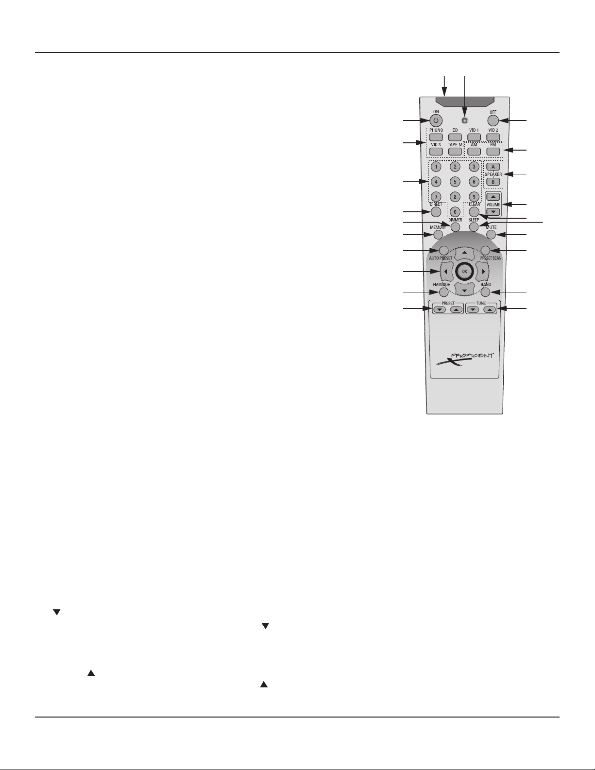
M40 REMOTE FEATURES
40
41
42
43
44
45
46
47
48
49
50 51
52
53
54
55
56
57
58
59
60
61
M40 REMOTE FEATURES
40. LENS -
41. ON -
42. SOURCE SELECT BUTTONS -
43. NUMERIC BUTTONS -
44. DIRECT -
45. DIMMER -
46. MEMORY -
Diagram 3 M40 Remote Control Features
47. AUTO PRESET -
48. CURSOR ARRAY/OK -
49. FM MODE -
50. PRESET -
PRESET -

13
M40 REMOTE FEATURES
51. TUNE -
TUNE -
52. BAND -
53. PRESET SCAN -
54. MUTE -
Note:
55. SLEEP -
56. CLEAR -
57. VOLUME -
58. SPEAKER A -
SPEAKER B -
59. AM -
FM -
60. OFF -
61. IR OUTPUT LED -

14
INSTALLATION
SP. A
2 INCH MINIMUM
FOR PROPER AIR FLOW
1 INCH MIN
FOR PROPER
AIR FLOW
1 INCH MIN
FOR PROPER
AIR FLOW
ALWAYS KEEP TOP AND
BOTTOM VENTS CLEAR
TO MAINTAIN PROPER AIR FLOW,
PLACE OTHER COMPONENTS
ON SEPARATE SHELVES
VENT HOLES IN SHELF IMPROVE AIR FLOW
Diagram 4 M40 Air Flow Requirements
AIR FLOW
1.
2.
3.
4.
5.
6.
7.

15
INSTALLATION
Ideal
Listening
Zone
Front
Left
Front
Right
A
B C
A=B=C
Video Display
Diagram 5 Speaker Placement
SPEAKER PLACEMENT
Determine The Ideal Listening Zone
Placement of Stereo Speakers
Bookshelf Speakers
Inwall Speakers
Ceiling Speakers
Subwoofer

16
CONNECTIONS
Subwoofer
Connections
Left
Speaker
Right
Speaker
16AWG Stranded
(minimum)
Speaker Wire
Control
IN
Audio
IN
White Stripe
To Positive
White Stripe
To Positive
Link S/W A
Switch ON
Sub
Audio IN
Sub
Control IN
RCA-RCA
Cable
(or appropriate)
Mini-Mini
Cable
(or appropriate)
M40
S/W A
Trigger Out
S/W A
Mono Out
A
B
A
B
SUBOUT
Diagram 6 Speaker & Subwoofer Connections
SPEAKER AND SUBWOOFER CONNECTIONS
Diagram 6
Note:
To connect multiple speaker pair to the M40, see Page 18.
Speaker A Connections
1.
2.
3. Diagram 7
4.
5.
6.
7.
8.
Diagram 7 Bare Wire Connections

17
CONNECTIONS
Speaker B
Note:
To connect multiple speaker pair to the M40, see Page 18.
Speaker B Connections
Sub Out
Diagram 6
Diagram 6
Note:
Sub Out A Connections
Audio
Trigger Out
Note:
Link S/W
Sub Out B Connections

18
CONNECTIONS
Multiple Pair Speaker Hookup For a Multiroom Sound System
WARNING: Never connect more than one pair of 8Ω speakers directly to the Speaker A and Speaker B Terminals at the same time. Doing
so can damage the M40. This type of damage is not covered by the Warranty. Always use an impedance matching device such as the
Procient VC60i Volume Control (one for each speaker pair) to protect the M40 from overload. Multiple 8Ω speaker pair can be connected
by adding one Procient VC60i Impedance Matching Volume Control to each speaker pair. Never connect more than one pair of 4Ω
speakers directly to the M40. Multiple 4Ω speaker pair connected directly to the M40 will cause the M40 to shut down and can damage
the M40. This type of damage is not covered by the Warranty. Multiple 4Ω speaker pair can be connected by adding one Procient VC60i
Impedance Matching Volume Control to each speaker pair.
Read and follow the instructions in this section when connecting multiple speaker pair to protect the M40 and help avoid
unnecessary damage.
Speaker Wire
Whole House Wire Requirement
1.
2.
SPEAKER WIRE LENGTH SPEAKER WIRE GAUGE
150' (46m) 16 AWG
400' (122m) 14 AWG
1,000' (305m) 12 AWG
Impedance Matching Volume Controls
Never install a volume control in a J-box with high voltage devices. This can introduce noise to the audio system and is a
violation of Building and Electrical Code in most places.

19
CONNECTIONS
1 2 3 4
SPEAKER IN
M40 REAR PANEL
Speaker A
Terminals
16AWG (min) 2-Conductor Stranded
Speaker Wire
PASSIVE (NON-IMPEDANCE MATCHING)
1 IN, 4 OUT SPEAKER TERMINAL
PROFICIENT
VC60i
IMPEDANCE MATCHING
VOLUME CONROLS
PROFICIENT
C645 CEILING
SPEAKERS
16AWG (min)
2-Conductor Stranded
Speaker Wire
Diagram 8 Whole House Music Connections
The maximum number of speakers that can be connected to the M40 using impedance matching volume controls is four
pair. All four pair should be connected to the Speaker A Terminal as shown in Diagram 8.
Setting Impedance
1. Chart 1
2.
3.
4.
5.
Number of 8Ω Speakers
Number of 4Ω Speakers
Chart 1 Procient VC60i Slide Switch Settings
4Ω Amp Conguration
VC60i Example 1:
Diagram 8
1.
2.
3.
4.
5.
VC60i Example 2:
1.
2.
3.
4.
5.

20
Multiple Speaker Pair Installation and Connections
Note:Diagram 8
1. Chart 1
Note:
2.
3. Diagram 7
4.
5.
6.
Diagram 8
7.
8.
9.
Note:Never install a volume control in a J-box with high voltage devices. This can introduce noise to the audio system and is a
violation of Building and Electrical Code in most places.
10.
11.
12.
CONNECTIONS
Table of contents


