Projoy Prosol-M600 User manual
用户手册 V1.1
1
User Manual
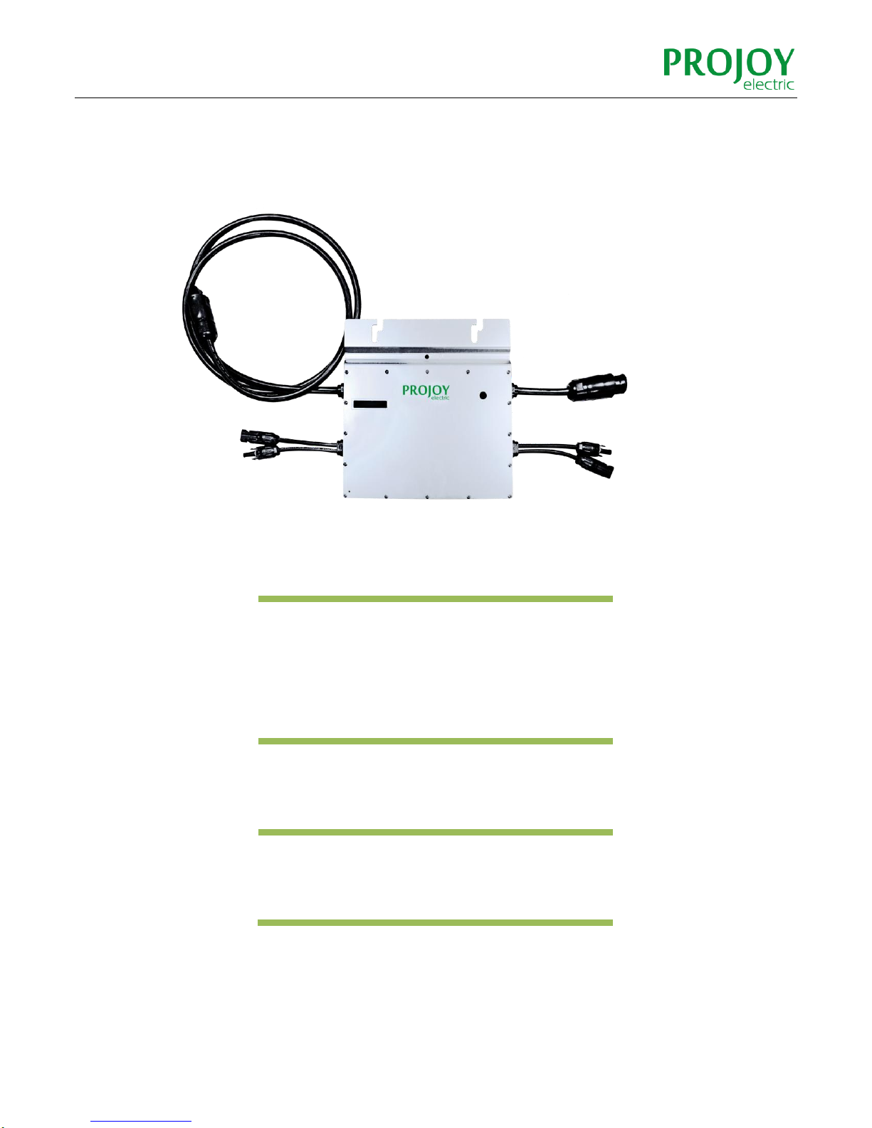
MICRO-INVERTER
Prosol-M600
PROJOY ELECTRIC SRL

2
Catalogue
1. INTRODUCTION ............................................................................................................... 3
2. SAFETY............................................................................................................................. 4
2.1 SYMBOL ILLUSTRATION ............................................................................................................. 4
2.2 INSTALLATION WARNINGS ........................................................................................................ 6
3. PREPARE FOR INSTALLING ........................................................................................... 7
3.1 TRANSPORT AND INSPECT......................................................................................................... 7
3.2 CHECK INSTALLATION ENVIRONMENT...................................................................................... 7
3.3 INSTALLATION POSITION........................................................................................................... 8
4. MOUNTING AND WIRING ................................................................................................ 9
4.1 INSTALLING DIAGRAM............................................................................................................... 9
4.2 ASSEMBLY INSTRUCTION......................................................................................................... 10
Step 1. Install Micro-inverter............................................................................................................. 10
Step 2. Connect AC Cable of Micro-inverter...................................................................................... 10
Step 3. Protecting Unused Ends ........................................................................................................ 10
Step 4. Connecting AC-TRUNK Cables to Junction Box...................................................................... 11
Step 5. Drawing System Map............................................................................................................. 12
Step 6. Install Photovoltaic Modules................................................................................................. 12
Step 7. Install CDD ............................................................................................................................. 13
5. MAINTENANCE GUIDE ...................................................................................................14
5.1 ROUTINE MAINTENANCE ........................................................................................................ 14
5.2 STORAGE AND DISMANTLING ................................................................................................. 14
6. APPENDIX........................................................................................................................15
6.1 TECHNICAL DATA..................................................................................................................... 15
6.2 CONTACT INFORMATION ........................................................................................................ 16
6.3 TEMPLATE FOR MAP OF MICRO-INVERTER INSTALLATION .................................................... 16

3
1. INTRODUCTION
Thank you for using M600 Micro-Inverter! This Micro-Inverter system is the world’s most
technologically advanced inverter system with benefits of efficient, flexible, safe and
reliable for use in utility-interactive applications.
This system is composed of a group of Micro-inverters that convert direct current (DC)
into alternating current (AC) and feeds it into the electric grid. Different from systems
that photovoltaic modules are subdivided into strings and controlled by one or several
inverters, this system is built for the incorporation of a Micro-inverter for each
photovoltaic module. Each Micro-inverter works independently of the others to
guarantee maximum power of each photovoltaic module. This setup enables direct
control over the production of a single photovoltaic module, consequently improving the
flexibility and reliability of the system.
This manual contains important instructions for the M600Micro-inverter and must be
read in its entirety before installing or commissioning the equipment. For safety, only
qualified technician, who has received train in gor has demonstrated skills can install
and maintain this Micro-inverter under the guide of this document.
4
2. SAFETY
IMPORTANT SAFETY INSTRUCTIONS!
PLEASE KEEP THIS INTRODUCTION IN A SAFE PLACE!
2.1 SYMBOL ILLUSTRATION
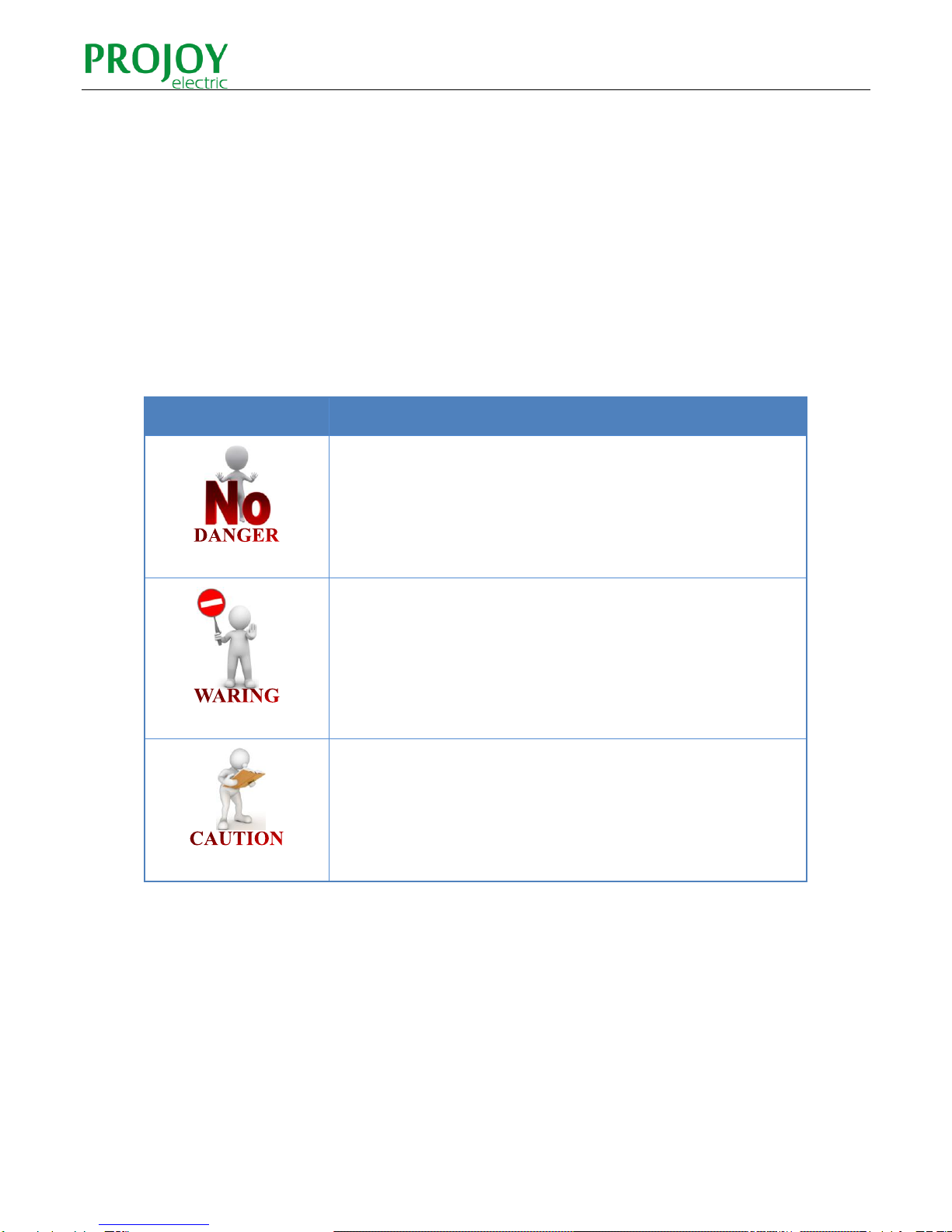
The safety symbols used in this manual are list below and illustrated in detail.
Symbol
Usage
Indicates a hazardous situation that can result in deadly electric
shock hazards, other serious physical injury, or fire hazards.
Indicates directions which must be fully understood and
followed in entirety in order to avoid potential safety hazards
including equipment damage or personal injury.
This points out that the described operation must not be carried
out. The reader should stop, use caution and fully understand
the operations explained before proceeding.

5
The symbols on the micro inverter are list below and illustrated in detail.
Symbol
Usage
Treatment
To comply with European Directive 2002/96/EC on waste
Electrical and Electronic Equipment and its implementation as
national law, electrical equipment that has reached the end of
its life must be collected separately and returned to an
approved recycling facility. Any device no longer required must
be returned to an author zed dealer or approved collection and
recycling facility.
Caution
Do not come within 8 inches (20cm) of the micro inverter for
any length of time while it is in operation.
Danger of high voltages
Danger to life due to high voltage in the micro inverter.
Beware of hot surface
The inverter can become hot during operation. Avoid contact
with metal surfaces during operation.
CE mark
The inverter complies with the requirements of the Low Voltage
Directive for the European Union.
Read manual first
Please read the installation manual first before installation,
operation and maintenance.

6
2.2 INSTALLATION WARNINGS
The M300 Micro-inverter is designed and tested according to international safety
requirements(IEC62109-1/-2, VDE4105, VDE0126, AS 4777.1 /.2& AS 3000). However,
certain safety precautions must be taken when installing and operating this inverter. The
installer must read and follow all instructions, cautions and warnings in this installation
manual
All operations including transport, installation, start-up and maintenance,
must be carried out by qualified, trained personnel.
Before installation, check the unit to ensure absence of any transport or
handling damage, which could affect insulation integrity or safety
clearances. Choose installation location carefully and adhere to specified
cooling requirements. Unauthorized removal of necessary protections,
improper use, incorrect installation and operation may lead to serious
safety and shock hazards or equipment damage.
Before connecting the Micro-inverter to the power distribution grid,
contact the local power distribution grid company to get appropriate
approvals. This connection must be made only by qualified technical
personnel .It is the responsibility of the installer to provide external
disconnects witches and Over current Protection Devices (OCPD).
Only one photovoltaic module can be connected in the input of the
inverter. Do not connect batteries or other sources of power supply. The
inverter can be used only if all the technical characteristics are observed
and applied.
Do not install the equipment in adverse environment conditions such as
flammable, explosive, corrosive, extreme high or low temperature, and
humid. Do not use the equipment when the safety devices do not work or
disabled.
Use personal protective equipment, including gloves and eye protection
when working.
Inform the manufacturer about non-standard installation conditions.
Do not use the equipment if any operating anomalies are found. Avoid
temporary repairs.
All repairs should be carried out using only qualified spare parts, which
must be installed in accordance with their intended use and by a licensed
contractor or authorized Projoy service representative.
Liabilities arising from commercial components are delegated to their
respective manufacturers.
Anytime the inverter has been disconnected from the power network, use
extreme caution as some components can retain charge sufficient to
create a shock hazard. Prior to touching any part of the inverter use care
to ensure surfaces and equipment are at touch safe temperatures and
voltage potentials before proceeding.
Projoy accepts No liability for damage from incorrect or careless
operation
Electrical Installation & Maintenance shall be conducted by licensed
electrician and shall comply with Australia National Wiring Rules

7
3. PREPARE FOR INSTALLING
3.1 TRANSPORT AND INSPECT
Projoy packages and protects individual components using suitable means to make the
transport and subsequent handling easier. Transportation of the equipment, especially
by road, must be carried out by suitable ways for protecting the components (in
particular, the electronic components) from violent, shocks, humidity, vibration, etc.
Please dispose the packaging elements in appropriate ways to avoid unforeseen injury.
It is the customer’s responsibility to examine the condition of the components
transported. Once receiving the Micro-inverter, it is necessary to check the container for
any external damage and verify receipt of all items. Call the delivering carrier
immediately if damage or shortage is detected .If inspection reveals damage to the
inverter, contact the supplier, or authorized distributor for are pair/return determination
and instructions regarding the process.
3.2 CHECK INSTALLATION ENVIRONMENT
Installation of the equipment is carried out based on the system design and the place in
which the equipment is installed.
The installation must be carried out with the equipment disconnected from the
grid(power disconnect switch open) and with the photovoltaic modules shaded or
isolated.
See Appendix: Technical Data to check the environmental parameters to be
observed (degree of protection, temperature, humidity, altitude, etc.)
To avoid unwanted power derating due to an increase in the internal temperature of
the inverter, do not expose it to direct sunlight.
To avoid overheating, always make sure the flow of air around the inverter is not
blocked.
Do not install in places where gasses or flammable substances may be present.
Avoid electromagnetic interference that can compromise the correct operation of
electronic equipment.

8
3.3 INSTALLATION POSITION
When choosing the position of installation, comply with the following conditions:
Install only on structures specifically conceived for photovoltaic modules (supplied by
installation technicians).
Install Micro-inverter underneath the photovoltaic modules so that they work in the
shade. If this condition cannot be met, the inverter could undergo derating.
Fig.1. Installation position of Micro-inverter
9
4. MOUNTING AND WIRING
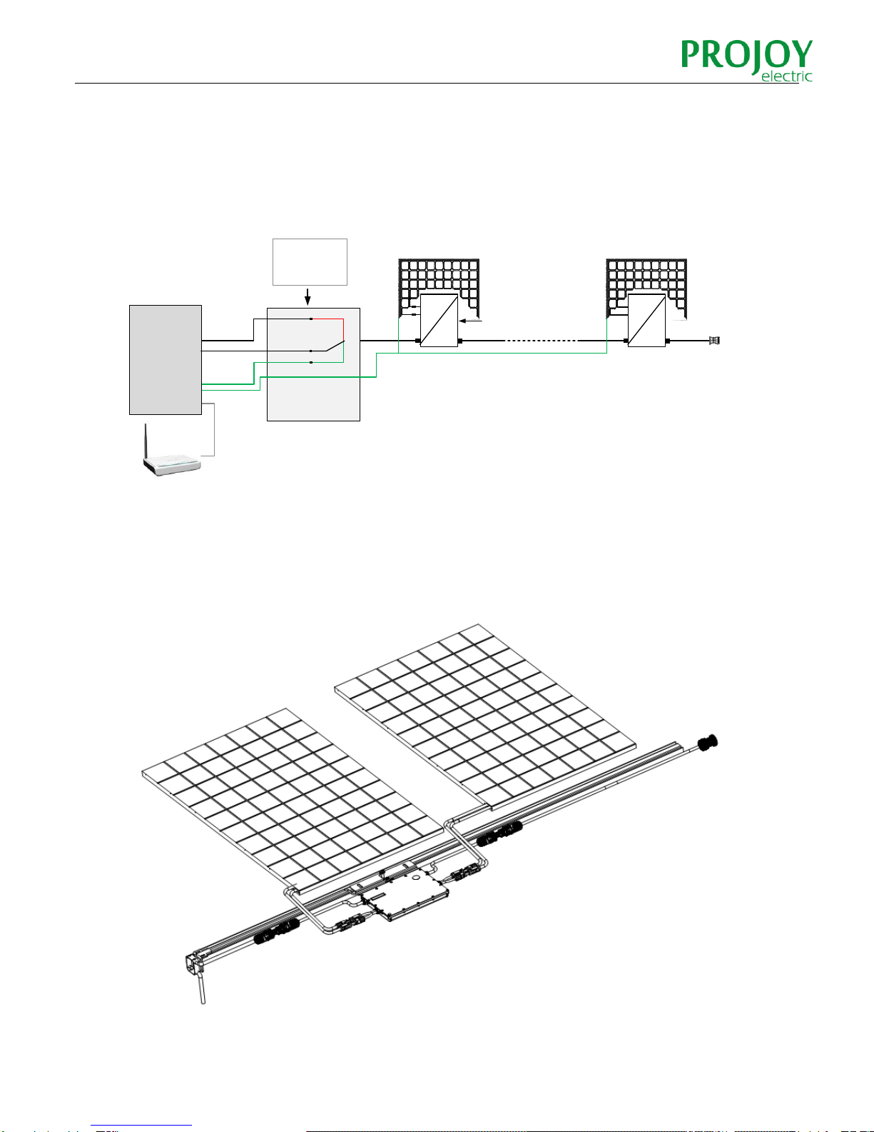
4.1 INSTALLING DIAGRAM
System Schematic Diagram
Fig.2. 230Vac single phase
Assembly Diagram
Fig.3. Assembly Illustration
DC
AC
…
Red:Live
Black:Neutral
Green:Ground
PV Module
Micro inverterAC Cable
Junction
Box
AC
Distribution
Panel
DC
AC
10
4.2 ASSEMBLY INSTRUCTION
Step 1. Install Micro-inverter
Mark the approximate center of each photovoltaic module on the frame and install the Micro-
inverter with the logo side facing downwards.
Observe the certification documents concerning the maximum number of
Micro- inverters permitted for installation at each cable section!
The Micro-inverter must be under the module, out of long-term exposure to direct
sunlight or rain.
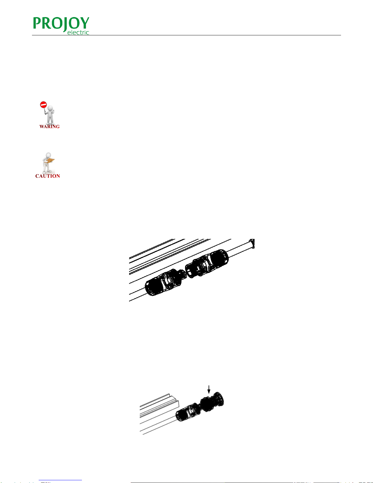
Step 2. Connect AC Cable of Micro-inverter
Connect the AC cable of the Micro-inverters. The connectors are coupled correctly when two
clicks are heard.
Fig.4. Connect AC Cable of Micro-inverter
Step 3. Protecting Unused Ends
The unused ends of the AC-TRUNK cable must be terminated with the proper end. Fit the
appropriate AC-TRUNK END CAP on the unused ends of the AC-TRUNK cable.
Fig.5. Unused Ends
AC End Cap

11
Step 4. Connecting AC-TRUNK Cables to Junction Box
Connect the AC-TRUNK cables coming from the MICRO inverters to the junction box. Close
the junction box after the wiring is complete. Ensure that the seal is tight.
Fig.6. Junction Box
To prevent electrical hazards, all the connection operations must be carried out with the
equipment disconnected from the grid.
All the external connections to the insulated junction box (caps, adapters, etc.)must be made
with securely-sealed Projoy components.
Projoy AC cables from the Micro-inverters have three conductors with different colors to identify the
function of each conductor:
Red: Live
Black: Neutral
Yellow-Green: Ground
Pay special attention and ensure not to reverse the phase with the neutral!
The installation technician is responsible for selecting a junction box with the appropriate
dimensions and insulation.
The installation technician is responsible for selecting a cable running between the junction box
and the load distribution panel with the appropriate length and cross section.

12
Step 5. Drawing System Map
Draw a map of the system, affixing the extra label that comes attached to each inverter, on the
appropriate position on the diagram (found in the Appendix of this manual).
Fig.7. System Map
Step 6. Install Photovoltaic Modules
Install the photovoltaic modules, and connect the DC cables of the modules to the
corresponding DC input side of the Micro-inverter.
Fig.8. Connect DC Cables
DC cable from PV module
DC cable from Microinverter
13
The recommended installation need keeping the Micro-inverters underneath the photovoltaic
modules, so that the Micro-inverters can operate in the shade. Direct sunlight may cause
damage to the Micro-inverters.
Each module must be connected to the Micro-inverters with a DC cable having a length of less
than 3m.
Step 7. Install CDD
Install the CDD (Concentrator Data Device) and commission
14
5. MAINTENANCE GUIDE
5.1 ROUTINE MAINTENANCE
Only authorized personnel are allowed to carry out the maintenance operations and are
responsible to report any anomalies.
Always use the personal protective equipment provided by the employer when carry out the
maintenance operation.
During normal operation, check that the environmental and logistic conditions are correct.
Make sure that the conditions have not changed over time and that the equipment is not
exposed to adverse weather conditions and has not been covered with foreign bodies.
DO NOT use the equipment if any problems are found, and restore the normal conditions
after the fault removed.
Conduct an annual inspection on various components, and clean the equipment with a
vacuum cleaner or special brushes.
Do not attempt to dismantle the Micro-inverter or make any internal repairs! In order to
preserving the integrity of safety and insulation, the Micro-inverters are not designed to allow
internal repairs!
The AC output wiring harness (AC drop cable on the Micro- inverter) cannot be replaced. If
the cord is damaged the equipment should be scrapped.
Maintenance operations must be carried out with the equipment disconnected from the grid
(power switch open) and the photovoltaic modules obscured or isolated, unless otherwise
indicated.
For cleaning, DO NOT use rags made of filamentary material or corrosive products that may
corrode parts of the equipment or generate electro static charges.
Avoid temporary repairs. All repairs should be carried out using only genuine spare parts.
5.2 STORAGE AND DISMANTLING
If the equipment is not used immediately or is stored for long periods, check that it is
correctly packed. The equipment must be stored in well-ventilated indoor areas that do not
have characteristics that might damage the components of the equipment.
Take a complete inspection when restarting after a long time or prolonged stop.
Please dispose the equipment properly after scrapping, which are potentially harmful to the
environment, in accordance with the regulations in force in the country of installation.

15
6. APPENDIX
6.1 TECHNICAL DATA
Model
Prosol-M600
Input data(DC)
Recommended input power (W)
200~310/200~310
MPPT voltage range (V)
27~48
Operating voltage range (V)
16~60
Maximum input voltage (V)
60
Maximum input current (A)
10/10
Inverter back feed current (A)
0
Output Data (AC)
Rated output power (W)
500
Rated output current (A)
2.17
Nominal output voltage/range (V)
230/200-270 1
Nominal frequency/range (Hz)
50/45.5-54.51
Power factor
>0.99
Output current harmonic distortion
<3%
Maximum Units per 20A Branch
7
Maximum output overcurrent protection (A)
20
Maximum output fault current (ac) and duration
Efficiency
Peak inverter efficiency
96.3%
CEC weighted efficiency
95.5%
Nominal MPPT efficiency
99.5%
Night time power consumption (mW)
<50
Mechanical Data
Dimensions (W×H×D mm)
252×250×28
Weight
2.8kg
Type of Enclosure
IP67
Cooling
Natural Convection
Environmental Data
Operating Ambient Temperature Range
-40°C to 65°C
Operating Internal Temperature Range
-40°C to 85°C
Relative Humidity
0-100 % condensing
Maximum Operating Altitude without Derating
2000m
ADD Pollution Rating
2
Overvoltage Category
OVC II for PV input circuit, OVC III for mains
circuit
Protective class
I
16
6.2 CONTACT INFORMATION
Headquarter
Projoy Electric SRL
Via Mazzini 18, 20066 Melzo (Milan) Italy
Tel: +39 02 8088 7095
Fax: +39 02 9573 9603
Website: www.projoy-electric.it
APAC Branch
ProJoy Electric Co., Ltd.
XinTang Industrial Zone, PingJiang District, Suzhou, China
Tel: +86 512 6878 6489
Fax: +86 512 6878 6489
Website: www.projoy-electric.com
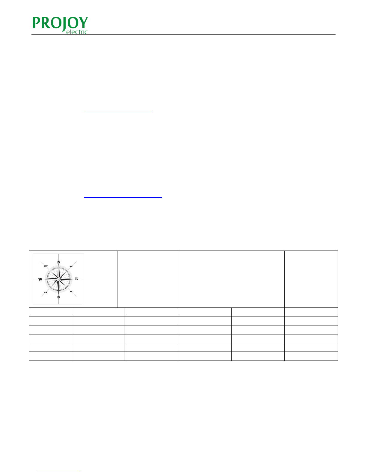
6.3 TEMPLATE FOR MAP OF MICRO-INVERTER INSTALLATION
Customer
Information:
Please affix the extra label that
comes from each inverter, on the
appropriate position on this
diagram.
1
2
3
4
5
A
B
C
D
E
Table of contents
Popular Inverter manuals by other brands


Coopers of Stortford
Coopers of Stortford G353 Instructions for use

Sofar solar
Sofar solar SOFAR 1100TL-G3 user manual

ProsKit
ProsKit TE-1203UB instruction manual

WEG
WEG bacnet CFW701 Addendum to the programming and troubleshooting manual

IO-Power Technology
IO-Power Technology IOP-DAPI-24243A-2 user manual

Magnum Energy
Magnum Energy RD1824 Operator's manual