Omega OTEC IEWQ Series User manual

IEWQ/ICHQ Series
High Wall Inverter
Technical Manual

Table of Contents
Table of Contents
Part Ⅰ: Technical Information.......................................................................1
1. Summary......................................................................................................................1
2. Specications..........................................................................................................2
2.1 Specication Sheet..................................................................................................2
2.2 Operation Characteristic Curve ..........................................................................4
2.3 Capacity Variation Ratio According to Temperature ...................................4
2.4 Cooling and Heating Data Sheet in Rated Frequency.................................5
3. Outline Dimension Diagram.........................................................................................6
3.1 Indoor Unit ..................................................................................................................6
3.2 Outdoor Unit...............................................................................................................7
4. Refrigerant System Diagram......................................................................8
5. Electrical Part...........................................................................................................9
5.1 Wiring Diagram .........................................................................................................9
5.2 PCB Printed Diagram............................................................................................11
Appendix:...................................................................................................................... 22
Appendix 1: Reference Sheet of Celsius and Fahrenheit............................... 22
Appendix 2: Configuration of Connection Pipe ................................................. 22
Appendix 3: Pipe Expanding Method..................................................................... 23
Appendix 4: List of Resistance for Temperature Sensor................................24

1
Technical Information
1. Summary
Part Ⅰ: Technical Information
Indoor Unit
Outdoor Unit
IEWQ036J3A-RWI100
ICHQ036J3A-RLH100
Remote Controller:

2
Technical Information
2. Specications
2.1 Specication Sheet
Model IEWQ036J3A-RWI100
Product Code CB434014900
CB432022800
Power Supply
Rated Voltage V~ 220-240
Rated Frequency Hz 50
Phases 1
Power Supply Mode Outdoor
Cooling Capacity(Min~Max) W 8840
Heating Capacity(Min~Max) W 9260
Cooling Power Input(Min~Max) W 2430
Heating Power Input(Min~Max) W 2350
Cooling Power Current A 11
Heating Power Current A 10.4
Rated Input W 3700
Rated Current A 11
Air Flow Volume(SH/H/MH/M/ML/L/SL) m3/h 1600/1300/1200/1100/950/850/-
Dehumidifying Volume L/h 3
EER W/W 3.64
COP W/W 3.94
SEER W/W /
SCOP W/W /
Application Area m235-52
Indoor Unit
Model of indoor unit IEWQ036J3A-RWI100
Indoor Unit Product Code CB434N14900
CB432N22800
Fan Type Cross-ow
Diameter Length(DXL) mm Φ108X522.7
Fan Motor Cooling Speed (SH/H/MH/M/
ML/L/SL) r/min 1550/1300/1200/1100/1000/950/850
Fan Motor Heating Speed (SH/H/MH/M/
ML/L/SL) r/min 1550/1300/1200/1100/1000/950/900
Output of Fan Motor W 70
Fan Motor RLA A 0.28
Fan Motor Capacitor μF /
Evaporator Form Aluminum Fin-copper Tube
Pipe Diameter mm Φ7
Row-n Gap mm 2-1.5
Coil Length (LXDXW) mm 1074X25.4X381
Swing Motor Model MP24BA/MP24CC/MP24CE
Output of Swing Motor W 1.5/1.5/1.5
Fuse A 5
Sound Pressure Level (SH/H/MH/M/ML/
L/SL) dB (A) 57/53/51/48/44/43/40
Sound Power Level (SH/H/MH/M/ML/L/
SL) dB (A) 67/63/61/58/54/53/50
Dimension (WXHXD) mm 1350X326X253
Dimension of Carton Box (LXWXH) mm 1438X418X352
Dimension of Package (LXWXH) mm 1441X421X367
Net Weight kg 18.5
Gross Weight kg 23

3
Technical Information
The above data is subject to change without notice. Please refer to the nameplate of the unit.
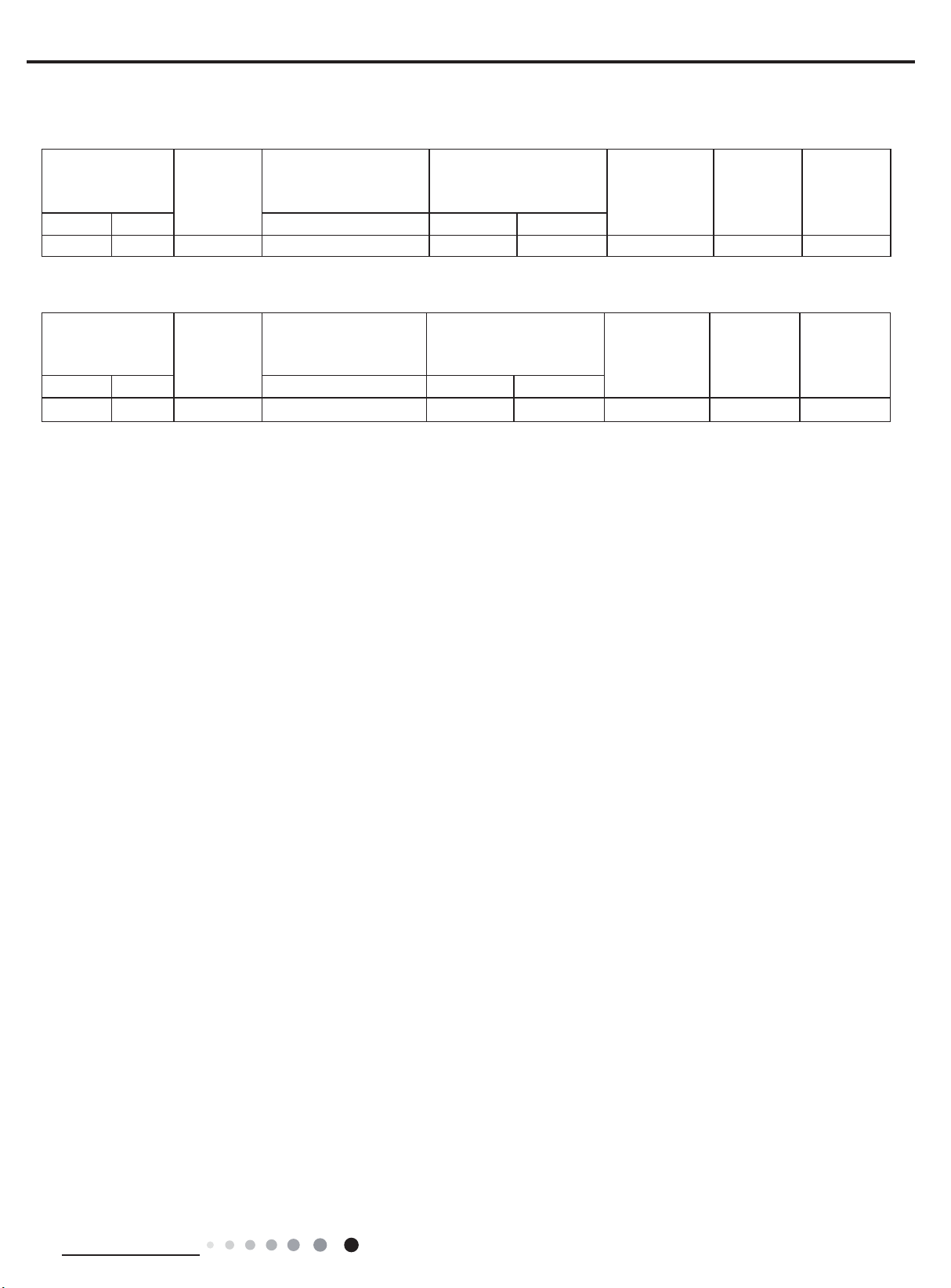
Outdoor Unit
Model of Outdoor Unit ICHQ036J3A-RLH100
Outdoor Unit Product Code CB434W14900
Compressor Manufacturer/Trademark ZHUHAI LANDA COMPRESSOR CO., LTD
Compressor Model QXFS-D25zX090H
Compressor Oil FW68DA
Compressor Type Rotary
Compressor L.R.A A 24
Compressor RLA A 12.50(60Hz)
Compressor Power Input W 2420 (60Hz)
Overload Protector 1NT11L-6233/ HPC115/95U1 /KSD115℃
Throttling Method Electron expansion valve
Operation temp OC 16~30
Ambient temp (cooling) OC 16~48
Ambient temp (heating) OC 2~24
Condenser Form Aluminum Fin-copper Tube
Pipe Diameter mm Φ7
Rows-n Gap mm 3-1.5
Coil Length (LXDXW) mm 994X57.1X748
Fan Motor Speed rpm 880
Output of Fan Motor W 90
Fan Motor RLA A 0.65
Fan Motor Capacitor μF /
Air Flow Volume of Outdoor Unit m3/h 4000
Fan Type Axial-ow
Fan Diameter mm Φ550
Defrosting Method Automatic Defrosting
Climate Type T1
Isolation I
Moisture Protection IPX4
Permissible Excessive Operating
Pressure for the Discharge Side MPa 4.3
Permissible Excessive Operating
Pressure for the Suction Side MPa 2.5
Sound Pressure Level (H/M/L) dB (A) 62/-/-
Sound Power Level (H/M/L) dB (A) 72/-/-
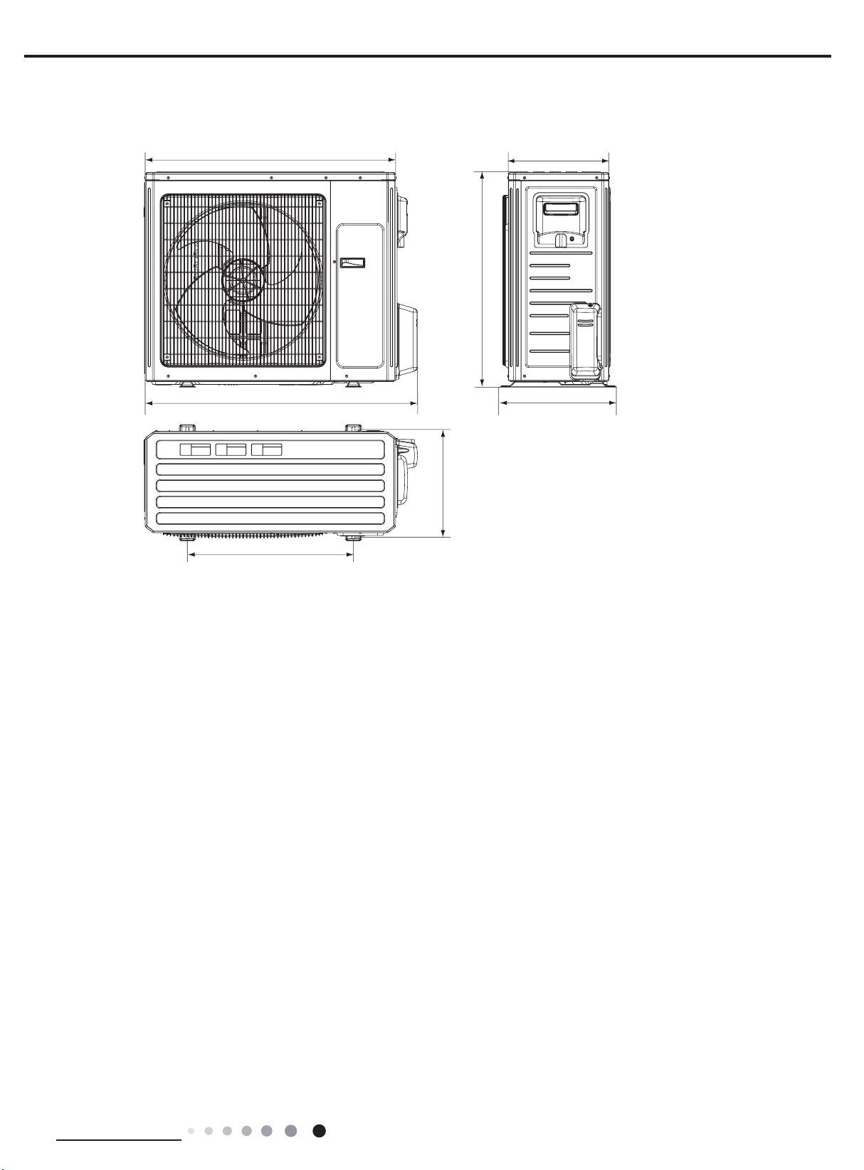
Dimension (WXHXD) mm 1003X790X427
Dimension of Carton Box (LXWXH) mm 1080X485X840
Dimension of Package (LXWXH) mm 1083X488X855
Net Weight kg 65
Gross Weight kg 70
Refrigerant R410A
Refrigerant Charge kg 2.3
Connection
Pipe
Length m 7.5
Gas Additional Charge mm 50
Outer Diameter Liquid Pipe mm Φ6
Outer Diameter Gas Pipe mm Φ16
Max Distance Height m 10
Max Distance Length m 25
Note:The connection pipe applies metric diameter.

4
Technical Information
2.2 Operation Characteristic Curve
2.3 Capacity Variation Ratio According to Temperature
01020304050607090010 20 30 40 50 60 70 80 90 100 120110
80
11
10
9
8
7
6
5
4
3
2
1
0
Compressor speed (rps)
)A(tnerruC
11
10
9
8
7
6
5
4
3
2
1
0
Compressor speed (rps)
)A(tnerruC
220V
230V
240V
220V
230V
240V
01020304050607090010 20 30 40 50 60 70 80 90 100 120110
80
11
10
9
8
7
6
5
4
3
2
1
0
Compressor speed (rps)
)A(tnerruC
11
10
9
8
7
6
5
4
3
2
1
0
Compressor speed (rps)
)A(tnerruC
220V
230V
240V
220V
230V
240V
Conditions
Indoor: DB27°C/WB19°C
Outdoor: DB35°C/WB24°C
Indoor air flow: High
Pipe length: 5m
Conditions
Indoor: DB27°C/WB19°C
Outdoor: DB35°C/WB24°C
Indoor air flow: High
Pipe length: 7.5m
Conditions
Indoor: DB20°C/WB15°C
Outdoor: DB7°C/WB6°C
Indoor air flow: High
Pipe length: 7.5m
Conditions
Indoor: DB20°C/WB15°C
Outdoor: DB7°C/WB6°C
Indoor air flow: High
Pipe length: 5m
Cooling Heating
Cooling
32 33 35 36 38 43
40 41 42
100
105
95
90
85
80
75
70
65
60
55
50
Conditions
Indoor:DB27°C/WB19°C
Indoor air flow:Super High
Pipe length:7.5m
Outdoor temp.(°C)
Capacity ratio (%)
Heating
–15 –10 –5
110
100
90
80
70
60
50
40
05710
Conditions
Indoor:DB20°C/WB15°C
Indoor air flow:Super High
Pipe length:7.5m
Outdoor temp.(°C)
Capacity ratio (%)
50
34 35 36 37 38 39 40 41 42 43 44 45 46 47 48
60
70
80
90
100
110
Capacity ratio(%)
Condition Cooling
Indoor:DB27°C WB19°C
Indoor air flow: Super High
Pipe length:7.5m
Capacity ratio(
%)
157-7 -5 02
24
0
20
40
60
80
100
120
-1 5
01
0
Outdoor Temp.(°C)
Outdoor Temp.(°C)
Condition Heating
Indoor:DB20
°C
Indoor air flow: Super High
Pipe length:7.5m
Cooling
Heating
Heating operation ambient temperature range is 2°C~24°C

5
Technical Information
2.4 Cooling and Heating Data Sheet in Rated Frequency
Instruction:
T1: Inlet and outlet pipe temperature of evaporator
T2: Inlet and outlet pipe temperature of condenser
P: Pressure at the side of big valve
Connection pipe length: 7.5 m.
Rated cooling
condition(°C)
(DB/WB) Model
Pressure of gas pipe
connecting indoor and
outdoor unit
Inlet and outlet pipe
temperature of heat
exchanger
Fan speed of
indoor unit
Fan speed of
outdoor unit
Compressor
frequency
(Hz)
Indoor Outdoor P (MPa) T1 (°C) T2 (°C)
27/19 35/24 36K 0.9 to 1.2 12 to 14 43 to 41 Super High High 56
Rated heating
condition(°C)
(DB/WB) Model
Pressure of gas pipe
connecting indoor and
outdoor unit
Inlet and outlet pipe
temperature of heat
exchanger
Fan speed of
indoor unit
Fan speed of
outdoor unit
Compressor
frequency
(Hz)
Indoor Outdoor P (MPa) T1 (°C) T2 (°C)
20/- 7/6 36K 2.0 to 2.5 40 to 39 2 to 5 Super High High 60
Cooling:
Heating:

6
Technical Information
3. Outline Dimension Diagram
3.1 Indoor Unit
Model WHD
36K
Unit:mm
WD
295 90
40
350 254746
Φ70
Φ70
H
28K
90
150
54
168.5 462 159.5
Φ55 Φ55
54
1350 326 253

7
Technical Information
3.2 Outdoor Unit
Unit:mm
1003
790
395
610
920 370
427

8
Technical Information
4. Refrigerant System Diagram
Connection pipe specication:
Liquid pipe:1/4" (6mm)
Gas pipe:5/8" (16mm)
Indoor unit Outdoor unit
COOLING
HEATING
4-Way valve
Discharge
Suction
Heat
exchanger
(evaporator)
Heat
exchanger
(condenser)
Valve
Valve
Liquid pipe
side
Gas pipe
side
Strainer Electric
expand
valve
Strainer
Capillary
Compressor
Accumlator

9
Technical Information
5. Electrical Part
5.1 Wiring Diagram
● Indoor Unit
● Instruction
Symbol Symbol Color Symbol Symbol Color Symbol Name
WH White GN Green CAP Jumper cap
YE Yellow BN Brown COMP Compressor
RD Red BU Blue Grounding wire
YEGN Yellow/Green BK Black / /
VT Violet OG Orange / /
Note: Jumper cap is used to determine fan speed and the swing angle of horizontal lover for this model.
60000700130505
3OHDVHGRQWWRXFKDQ\
HOHFWURQLFFRPSRQHQWRU
WHUPLQDOZKHQWKHPDFKLQH
LVUXQQLQJVWRSSLQJRUKDV
EHHQSRZHUHGRIIIRUOHVV
WKDQPLQXWHVWRSUHYHQW
HOHFWULFVKRFN
287'22581,7
%8
%.
%1
<(*1
%/2&.
52207(03
78%(7(03
6(1625
6(1625
',63/$<%2$5'
5(&(,9(5$1'
0$,1%2$5'
-803
&$3 $3
6:,1*8'
78%(5220
$&/
$3
',63',63
0
3(
'&02725
(9$325$725
%.
1
<(*1
&20287
1
%1
%8
;7
7575
/
/
7(50,1$/
02725
67(33,1*
83'2:1
0
)$102725
$3
:,),02'8/(
237,21$/
:,), /
/
0$*1(7,&
5,1*
3(
<(*1
237,21$/
6:,1*/5
0
02725
67(33,1*
/()75,*+7
6:,1*/5
0
02725
67(33,1*
/()75,*+7 &2/'3/$60$
*(1(5$725
%85'
:$51,1*
'225&
$3
'5<&
'5<&217$&7
+($/7+/+($/7+1

10
Technical Information
60000706170802
● Outdoor Unit
These circuit diagrams are subject to change without notice, please refer to the one supplied with the unit.
3OHDVHGRQWWRXFKDQ\
HOHFWURQLFFRPSRQHQWRU
WHUPLQDOZKHQWKHPDFKLQHLV
UXQQLQJVWRSSLQJRUKDV
EHHQSRZHUHGRIIIRUOHVV
WKDQPLQXWHVWRSUHYHQW
WKHULVNRIHOHFWULFVKRFN
:$51,1*
&20,11(5
1
$&B/
/
1
<(*1
%8
3(
1
/
1
%1
%.
%8
;7
,1'22581,7
5,1*
%1
%8
%/2&.
7(50,1$/
0$*1(7,&
32:(5
%1%.
76(1625
&203
:
9
8
35,17('&,5&8,7%2$5'
3(
<(*1
)$102725
:$< 2)$1)$
7979
9$/9(
<9
:$<
0 3(
(.9
(OHFWURQLF
([SDQVLRQ
9DOYH
3(
<(*1
3(
5,1*
0$*1(7,&
29(5/2$'3527(&725
:5'9<(8%8
<(%8 5'
57 57 57
5'
29&&203
+:+:
6$7
&203
;
<(%8
:+ %.
7(036(1625
28778%(
2875220
7(036(1625
(;+$867
7(036(1625
$3
...
<(*1
3(
/
/
%8
%1
%.
/
/ / /
LURQVKHOOPRWRU
RQO\DSSOLHVWRWKH
127(0RWRUJURXQG
/
/
/
5,1*
0$*1(7,&
/

11
Technical Information
5.2 PCB Printed Diagram
Indoor Unit
1
12
13
14
15
234567
8
9
10
11
No. Name
1 Neutral wire
2 Live wire
3 Jump
4Interface of dry contact(only for
the model with this function)
5 Relay used for controlling wire
6Auto key
7 up&down swing interface
8WIFI
9Interface of ambient temperature sensor
10 Interface of tube temperature sensor
11 Display board
12 Interface of communication wire
for indoor unit and outdoor unit
13 Interface of health function live wire
14
15
Fuse
(Applicable for some models)
Interface of health function neutral wire
●Top view
●Bottom view

12
Technical Information
Outdoor Unit
Top View
Bottom View
NO. Name NO. Name NO. Name
1 Compressor three phase input interface 6Terminal of high pressure protection 11 Te rminal of chassis electric heating
2Terminal of low ambient temperature
cooling temperature sensor 7Terminal of low pressure protection 12 Terminal of live wire
3Terminal of electronic expansion valve 8Terminal of outdoor fan13Terminal of communication
4Terminal of outdoor temperature sensor 9Terminal of compressor electric heating 14 Te rminal of grounding wire
5Terminal of compressor overload
protection 10 Terminal of 4-way valve15Terminal of neutral wire
1
23 4567 8910
11
12
13
14
15

14
Technical Information
● When selecting auto mode, air conditioner will operate automatically according to the sensed temperature.
.deeps naf tsujda nac nottub "NA " sserP .llew sa deyalpsid eb ton lliw dna detsujda eb t’nac erutarepmet teS F
Press " " / " "
button can adjust fan blowing angle.
● After selecting cool mode, air conditioner will operate under cool mode. Cool indicator " " on indoor unit is ON.(This
indicator is not available for some models)
nottub " " / " " sserP .deeps naf tsujda
ot nottub "NAF"
sserP .erutar -epmet tes tsujda ot nottub " " ro "▲" sserP.
.elgna gniwolb naf tsujda ot
● When selecting dry mode, the air conditioner operates at low speed under dry mode. Dry indicator " " on indoor unit
.elgna gniwolb naf tsujda ot nottub " " / " " sserP .detsujda eb t’nac deeps naf ,edom yrd rednU
(This indicator is not available for some models).NO si
● When selecting fan mode, the air conditioner will only blow fan, no cooling and no heating. All indicators are OFF,
.elgna gniwolb naf tsujda ot nottub " " / " "sserP .deeps naf tsujda ot nottub "NAF" sserP
.(This indicator is not available for some models)NO si rotacidni noitarepO
● When selecting heating mode, the air conditioner operates under heat mode. Heat indicator " " on indoor unit is
"FAN" button sserP .erutarepmet tes tsujda ot nottub " " ro "▲" sserP
NO
to adjust fan speed. Press " " / " " button to adjust fan blowing angle. (Cooling only unit won’t receive heating mode
signal. If setting heat mode with remote controller
,.
)tinu eht pu trats t’nac nottub FFO/NO sserp
▲
▲
AUTO COOL FANDRYHEAT
Note:
● For preventing cold air, after starting up heating mode, indoor unit will delay 1~5 minutes to blow air (actual delay time
is depend on indoor ambient temperature).
● Set temperature range from remote controller: 16~30 (61-86°F);
Fan speed: auto, low speed, low-medium speed,
medium speed,medium-high speed,high speed.
3.FAN button
This button is used for setting Fan Speed in the sequence that goes from AUTO, to
then back to Auto.
,,, ,
Auto
Medium speedLow-Medium speedLow speed
High speedMedium-High speed
Note:
4.TURBO button
Under COOL or HEAT mode, press this button to turn to quick COOL or quick HEAT mode. " " icon is displayed on
remote controller. Press this button again to exit turbo function and " " icon will disappear.
If start this function, the unit will run at super-high fan speed to cool or heat quickly so that the ambient temp. approachs
the preset temp. as soon as possible.
▲
5.▲/ button
● Press "▲" or " " button once increase or decrease set temperature 1 (°F). Holding "▲" or " " button, 2s later,
-acidni erutarepmet ,dehsinfi si gnittes retfa nottub gnisaeler nO .ylkciuq egnahc lliw rellortnoc etomer no erutarepmet tes
tor on indoor unit will change accordingly
. (Temperature can’t be adjusted under
▲
▲
● It’s Low fan speed under Dry mode.
This function indicates that moisture on evaporator
of indoor unit will be blowed a fter the unit is stopped to avoid mould.
Having set X-FAN function on: A rof gninnur eunitnoc lliw naf roodni nottub FFO/NO gnisserp yb tinu eht ffo gninrut retf
,doirep siht nI .deeps wol ta .setunim wef a Hold fan speed button for 2s to stop indoor fan directly.
ltcerid ffo eb lliw tinu etelpmoc eht ,nottub FFO/NO gnisserp yb tinu eht ffo gninrut retfA :ffo noitcnuf NAF-X tes gnivaH y.
X-FAN function Hold fan speed button for 2s in COOL or DRY mode, the icon “ ” is displayed
and the
indoor fan will
continue
operation for a few minutes in order to dry the indoor unit even though you have turned off the unit. After energization, X-FA
N
OFF is defaulted. X-FAN is not available in AUTO, FAN or HEAT mode.
●
●
●
▲
auto mode)
● When setting TIMER ON, TIMER OFF or CLOCK, press "▲" or " " button to adjust time. (Refer to CLOCK, TIMER ON,
TIMER OFF buttons)
(This indicator is not available for some models).

15
Technical Information
Note:
● Press this button continuously more than 2s, the main unit will swing back and forth from left to right, and then loosen
the button,the unit will stop swinging and present position of guide louver will be kept immediately
.
● Under swing left and right mode, when the status is switched from off to , if press this button again 2s later,
status will switch to off status directly; if press this button again within 2s, the change of swing status will also depend on
the circulation sequence stated above.
Press this button can select up & down swing angle. Fan blow angle can be selected
circularly as below:
● When selecting " ", air conditioner is blowing fan automatically. Horizontal louver will automatically swing up & down at
maximum angle.
● When selecting " ǃ ǃ ǃ ǃ ", air conditioner is blowing fan at fixed position. Horizontal louver will stop at the fixed
position.
● When selecting " ǃ ǃ ", air conditioner is blowing fan at fixed angle. Horizontal louver will send air at the fixed angle.
● Hold " " button above 2s to set your required swing angle. When reaching your required angle, release the button.
Note:
● " ǃ ǃ " may not be available. When air conditioner receives this signal, the
air conditioner will blow fan automatically
.
● Press this button continuously more than 2s, the main unit will swing back and forth from up to down, and then loosen
the button, the unit will stop swinging and present position of guide louver will be kept immediately.
● Under swing up and down mode, when the status is switched from off to , if press this button again 2s later,
status will switch to of
f status directly; if press
no display
(horizontal louvers stops
at current position)
button
this button again within 2s, the change of swing status will also depend on the
circulation sequence stated above.
Press this button can select left & right swing angle. Fan blow angle can be selected
circularly as below:
button
no display
(stops at current position)
6.
7.
main unit setting temperature will increase 1 , two hours, setting temperature increa- sed 2
setting temperature; In Heat mode: sleep status after run for one hour, the setting temperature will decrease 1 , two hours,
setting temperature will decrease 2 , then the unit will run at this setting temperature.
● Sleep 2 is sleep mode 2, that is air conditioner will run according to the presetting a group of sleep temperature curve.
● Sleep 3-the sleep curve setting under S leep mode by DIY;
(1)Under Sleep 3 mode, press “Turbo” button for a long time, remote controller enters into user individuation sleep
setting status, at this time, the time of remote controller will display “1hour”, the setting temperature “88” will display
the corresponding temp- erature of last setting sleep curve and blink (The first entering will display according to
the initial curve setting value of original factory);
(2)Adjust "▲" and " " button, could change the corresponding setting temperature, after adjusted, press “Turbo” button
for confirmation;
(3) At this time, 1hour will be automatically increased at the timer postion on the remote
or "8hours"), the place of setting temperature "88" will display the corresponding temperature of last setting sleep curve and blink;
(4) Repeat the above step (2)~(3) operation, until 8 hours temperature setting finished, sleep,curve setting finished, at this time,
the remote controller will resume the original timer display; temperature display will resume to original setting temperature.
8.SLEEP button
8
● Press this button, can select Sleep 1 ( ), Sleep 2 ( ), Sleep 3 ( ) and cancel the Sleep, circulate between these,
after electrified, Sleep Cancel is defaulted. after run for one hour, the
▲
Sleep 1 is Sleep mode 1, in Cool modes; sleep status
, then the unit will run at this
control, (that are "2hours" or "3hours"

16
Technical Information
9.I FEEL button
Press this button to start I FEEL function and " " will be displayed on the remote controller. After this function is set,
the remote
controller will send the detected ambient temperature to the controller and the unit will automatically adjust the indoor
temperature according to the detected temperature. Press this button again to close I FEEL function and " " will disappear.
● Please put the remote controller near user when this function is set. Do not put
●
Sleep3- the sleep curve setting under Sleep mode by DIY could be inquired:
The user could accord to sleep curve setting method to inquire the presetting sleep curve,
enter into user individuation sleep
setting status, but do not change the tempera-ture, press “Turbo” button directly for confirmation. Note: In the above presetting or
enquiry procedure, if continuously within 10s, there is no button pressed, the sleep curve setting within 10s, there is no button
pressed,
the sleep curve setting status will be automatically quit and resume to display the original displaying. In the presetting or
enquiry procedure, press
"ON/OFF" button, "Mode" button, "Timer" button or "Sleep" button, the sleep curve setting
or enquiry status will quit similarly.
Press this button to set clock time. " " icon on remote controller will blink. Press "▲" or " " button within 5s to set clock time.
Each pressing of "▲" or " " button, clock time will increase or decrease 1 minute. If hold "▲" or " " button, 2s later,
time will change quickly. Release this button when reaching your required time.
Press "CLOCK" button to confirm the time. " " icon stops blinking.
Note:
● Clock time adopts 24-hour mode.
● The interval between two operation can’t exceeds 5s. Otherwise, remote contro- ller will quit setting status. Operation for
TIMER ON/TIMER OFF is the same.
11.CLOCK button
▲
▲
▲
Note:
● Under on and off status, you can set TIMER OFF or TIMER ON simultaneously.
● Before setting TIMER ON or TIMER OFF, please adjust the clock time.
● After starting up TIMER ON or TIMER OFF, set the constant circulating valid.
After that, air conditioner will be turned on or turned off according to setting time.
ON/OFF button has no effect on setting. If you don’t need this function, please use remote controller to cancel it.
temperature or low temperature in order to avoid detecting inaccurate
the remote controller near the object of high
When I FEEL function is turned on, the remote controller should be put within the area where indoor unit can receive the
signal sent by the remote controller.
ambient temperature.
●
TIMER ON button
"TIMER ON" button can set the time for timer on.
After pressing this button, " "
remote controller blinks. Press "▲" or
icon disappears and the word "ON" on
" " button to adjust
TIMER ON setting.
After each pressing "▲" or " " button,
TIMER ON setting will increase or decrease 1min. Hold "▲" or " " button, 2s later , the time will change quickly
until reaching your required time. Press "TIMER ON" to confirm it.
The word "ON" will stop blinking. " " icon
resumes displaying. Cancel
TIMER ON: Under the condition that
TIMER ON is started up, press "TIMER ON"
button to cancel it.
● TIMER OFF button
"TIMER OFF" button can set the time for timer off. After pressing this button," "
on remote controller blinks. Press "▲" or
icon disappears and the word "OFF"
" " button to adjust
TIMER OFF setting.
After each pressing "▲" or " " button,
TIMER OFF setting will increase or decrease 1min. Hold "▲" or " " button, 2s
later , the time will change quickly
until reaching your required time.
Press "TIMER OFF" word "OFF" will stop blinking. " " icon resumes displaying.
Cancel TIMER OFF. Under the condition that TIMER OFF is started up, press "TIMER OFF" button to cancel it.
▲
▲
▲
▲
10.TIMER ON /
TIMER OFF button
▲▲
12.QUIET button
Press this button, the Quiet status is under the Auto Quiet mode (display " " and "AUTO" signal ) and Quiet mode
(display " " singal) and Quiet OFF (there is no signal of " " displayed), after powered on, the Quiet OFF is defaulted.
Note:
●
The Quiet function can be set up in all modes; Under the Quiet mode,
the fan speed is not available.
● When quiet function is selected:
Under cooling mode: indoor fan operates at notch 4 speed. 10 minutes later or
when indoor ambient temperature≤28Ƈ
, indoor fan will operate at notch 2 speed or quiet mode according to the compari son between indoor ambinet temperature
and set temperature.
Under heating mode: indoor fan opera
te s at notch 3 speed or quiet mode according to the comparison between indoor
ambient temperature and set temperature.
actual cooling, heating or fan mode.
Under dry, fan mode: indoor fan operates at quiet mode.
Under auto mode: the indoor fan opera
tes at the auto quiet mode according to

17
Technical Information
14.LIGHT button
Press this button to turn off display light on indoor unit. " " icon on remote controller disappears. Press this button again
to turn on display light. " " icon is
displayed.
Press this button to achieve the on and off of healthy and scavenging functions in operation status. Press this button for
the first time to start scavenging function;
button
15.
13.WiFi button
● This function is only available for some models.
Press " WiFi " button to turn on or turn off WiFi function. When WiFi function is turned on, the " " icon will be displayed
WiFi
on remote controller; Under status of unit off, press "MODE" and " WiFi " buttons simultaneously for 1s, WiFi module
will restore to factory default setting.
●
The Quiet function is only available for some models.
actual cooling, heating or fan mode.
Under auto mode: the indoor fan operates at the auto quiet mode according to
16.TEMP button
By pressing this button, you can see indoor set temperature, indoor ambient temp- erature or outdoor ambient temperature
on indoor unit ’s display. The setting on remote controlleris selected circularly as below:
no display
LCD displays " ". Press the button for the second time to start healthy and
scavenging functions simultaneously; LCD displays " " and " " . Press this button for the third time to quit healthy and
scavenging functions simultaneously
.
Press the button for the fourth time to start healthy function; LCD display " " .
Press this button again to repeat the operation above.
●
This function is applicable to partial of models.
Energy-saving function
Under cooling mode, press "TEMP" and "CLOCK" buttons simultaneously to start up or turn off energy-saving function.
When energy-saving function is started
up, "SE" will be shown on remote controller, and air conditioner will adjust the set
temperature automatically according to ex-factory setting to reach to the best energy-saving effect. Press "TEMP" and "CLOCK"
buttons simultaneously again to exit energy-saving function.
Note:
● Under energy-saving function, fan speed is defaulted at auto speed and it can’t be adjusted.
● When selecting " " or no display with remote controller, temperature indicator on indoor unit displays set temperature.
● When selecting " " with remote controller, temperature indicator on indoor unit displays indoor ambient temperature.
● When selecting " " with remote controller, temperature indicator on indoor unit displays outdoor ambient temperature.
Note:
●
Outdoor temperature display is not available for some models. At that time, indoor
unit receives " " signal, while it displays
indoor set temperature.
● It’s defaulted to display set temperature when turning on the unit.There is no display in the remote controller.
● Only for the models whose indoor unit has dual-8 displa y.
● When selecting displaying of indoor or outdoor ambient temperature, indoor temperature indicator displays corresponding
temperature and automatically turn to display set temperature after three or five seconds.
●
Under energy-saving function, set temperature can’t be adjusted. Press "TURBO"
button and the remote controller won’t send
signal.
● Sleep function and energy-saving function can’t operate at the same time. If energy-saving function has been set under
cooling mode, press sleep button will cancel energy-saving function. If sleep function has been set under cooling mode, start
up the energy-saving function will cancel sleep function.

18
Technical Information
Child lock function
Multi timer function
Press "▲" and " " simultaneously to turn on or turn off child lock function. When child lock function is on, " " icon is
displayed on remote controlle
r . If you operate the remote controller, the " " icon will blink three times without sending signal to
the unit.
▲
Te
mperature display switchover function
Under OFF status, press " " and "MODE" buttons simultaneously to switch temp-erature display between ć and .
▲
Note:
● Under 8ć heating function, fan speed is defaulted at auto speed and it can’t be
adjusted.
● Under 8ć heating function, set temperature can’t be adjusted. Press
"
TURBO
"
button and the remote controller won’t
send signal.
● Sleep function and 8ć heating function can’t operate at the same time. If 8ć
cooling mode, press sleep button will cancel 8ć heating function. If sleep function has been set under cooling mode, start up
the 8ć heating function will cancel sleep function.
● Under temperature display, the remote controller will display 46
If “H1” is displayed on the remote controller while it’s not operated by the professional person/after-sales person, it belongs to the
misoperation.
Please operate it as below to cancel it.Under the OFF status of remote controller, hold the Mode button for 5s to cancel “H1”
display.
Note:
● If remote controller displays “H1”, it belongs to the normal function reminder. If the unit is defrosting under heating mode, it
operates according to H1 defrosting mode. “H1” won’t be displayed on the panel of indoor unit;
● Once you set H1 mode, if you turn off unit by remote controller, H1 will display 3 times on the remote controller and then
disappear;
● Also, when you set H1 mode, when you change to heating mode, H1 will display 3 times on the remote controller and then
disappear.
heating.
8ćheating function
Under heating mode, press "TEMP" and "CLOCK" buttons simultaneously to start
up or turn off 8
ć
heating function. When
this function is started up, " " and "8
ć
"
will be shown on remote controller, and the air conditioner keep the heating status
at 8ć. Press "TEMP" and "CLOCK" buttons simultaneously again to exit 8ćheating function.
heating function has been set under
Replacement of batteries in remote controller
● THREE TIMERS
● TWO TIMERS
● TIMER CANCELLATION
NOTE:
1. Press the back side of remote controller marked
Press uninterruptedly “LIGHT” button 6 times in 5 seconds thus we enter the “Multi Timer” mode as well as three-minute-
counting-down stars. If three couples of times commands are valid and well-received in 3 minutes, the “Multi Timer” will be
activated along with the success sound of four buzzing, and the former “Multi Timer” settings with be replaced. If not, then
“Multi Timer” mode exits along with the failure sound of six buzzing, and the former “Multi Timer” settings still remain effective.
Press uninterruptedly “LIGHT” button 4 times in 5 seconds thus we enter the “Multi Timer” mode as well as two-minute-counting
-down stars. If two couples of times commands are valid and well-received in 2 minutes, the “Multi Timer” will be activated
along with the success sound of four buzzing, and the former “Multi Timer” settings with be replaced. If not, then “Multi Timer”
mode exits along with the failure sound of six buzzing, and the former “Multi Timer” settings still remain effective.
with " ", as shown in the
fig, and then push out
the cover of battery box along the arrow direction.
2. Replace two 7# (AAA 1.5V) dry batteries, and make sure the position of
"+" polar and "-" polar
are correct.
3. Reinstall the cover of battery box.
Press uninterruptedly “LIGHT” button 8 times in 5 seconds all the “Multi Timer”settings will be erased.
signal sender battery
Cover of battery box
remove
reinstall
● During operation, point the remote control signal sender at the receiving window on indoor unit.
● The distance between signal sender and receiving window should be no more than 8m, and there should be no obstacles
between them
.
● Signal may be interfered easily in the room where there is fluorescent lamp or wireless telephone; remote controller should
be close to indoor unit during operation.
● Replace new batteries of the same model when replacement is required.
● When you don’t use remote controller for a long time, please take out the batteries.
● If the display on remote controller is fuzzy or there ’s no display, please replace batteries.

21
Technical Information
6.4 Brief Description of Modes and Functions
1 Temperature Parameters
Indoor preset temperature (Tpreset)
Indoor ambient temperature (Tamb.)
2
Basic Functions (The temperature in this manual is expressed by Centigrade. If Fahrenheit is used, the switchover
be
tween them is Tf=TcX1.8+32.)
Once the unit is energized, the compressor shall never be restarted except 3mins interval at least. For the first energization
,
if the unit is at off status before po
wer failure, the compressor can be restarted without 3-min delay. But if the unit is at on
status before po
wer failure, the compressor shall be restarted with 3mins delay. Once the compressor is started up, the
compressor
won't stop running within 6mins with the change of room temperature.
(1) Cooling mode
Cooling conditions and process
When Tamb.
≥Tprese+1 , the unit starts cooling operation. In this case, the compressor and the outdoor fan operate and
the indoor fan operates at set speed
.
When Tamb. ≤Tpreset-1
, the compressor and the outdoor fan stop while the indoor fan operated at set speed.
When Tpreset-
1Tamb. Tpreset+1 , the unit will maintain its previous operation status.
In
this mode, the four-way valve is de-energizing. The temperature setting range is 16 30 and the indoor unit displays
operation icon, cooling icon and set temperature.
Protection Functions
Antifreezing protection
If the system is under antifreezing protection, the compressor and the outdoor fan stops operation, and the indoor fan
operates at setting speed. If antifreezing protection is eliminated and the compressor has been stopped for 3 minutes, the
unit will resume its previous operation status.
Tpreset +1 ˚C
Tpreset –1 ˚C
Compressor
Outdoor fan
Indoor fan
Run
Tamb.
Stop cooling
Start cooling
Original operating status
≥ 6 min. ≥ 3 min. ≥ 6 min.
Setting fan speed
If the system current exceeds the specified value in 3 successive seconds, except indoor fan, the complete unit will stop
operation. After 3 minutes, if the overcurrent is eliminated, the complete unit will resume previous operation.
If overcurrent protection occurs for 6 successive times (if the compressor operates for 6 minutes continuously, the
protective times will be cleared.), except indoor fan, the complete unit will stop operation. In this case, you should turn off
the unit by remote controller and then restart it. During overcurrent protection, the nixie tube displays error code “E5”, an
d
operation indicator lamp blinks (OFF 3 seconds and blinks 5 times).
(2) Dry Mode
Dry Conditions and Process
Overcurrent Protection
Stop
During antifreeze protection
Compressor
Outdoor fan
Indoor fan
min
Preset speed
RunStop
Other manuals for OTEC IEWQ Series
2
This manual suits for next models
6
Table of contents
Other Omega Inverter manuals
Popular Inverter manuals by other brands

Rohde & Schwarz
Rohde & Schwarz Hameg HM8150 user manual

Forza
Forza Fusion Series user manual

Vanner
Vanner 20-1000TUL owner's manual

Fuji Electric
Fuji Electric frenic-hvac instruction manual

Kipor
Kipor Sinemaster IG2000i Operation manual

Chicago Electric
Chicago Electric 66817 Set up and operating instructions