Prolyte LiteDeck Operating instructions

LiteDeck User Installation Guidance
1
LiteDeck
User installation guidance
WWW.PROLYTE.COM

LiteDeck User Installation Guidance
2
CONTENTS
1. LITEDECK INSTALLATION 3
- GENERAL 3
- TOOLS NEEDED 3
- THE OUTLINE PROCESS 3
- SECTION 1 3
- SECTION 2 4
- SECTION 3 5
- SECTION 4 6
- SECTION 5 8
-LITEDECK TECHNICAL INFORMATION 9
PROLYTE GROUP© 2015
Prolyte has made every effort to ensure the accuracy of this manual; no liability will be
accepted for errors. Prolyte reserves the right to change or alter its products or manuals
without prior notice. No part of this manual may be reproduced in any form or by any means
without prior written permission.
PROLYTE GROUP - phone +31 (0)594 85 15 15 WWW.PROLYTE.COM
VERSION 1.0 - SEPTEMBER 2015
LiteDeck User Installation Guidance
3
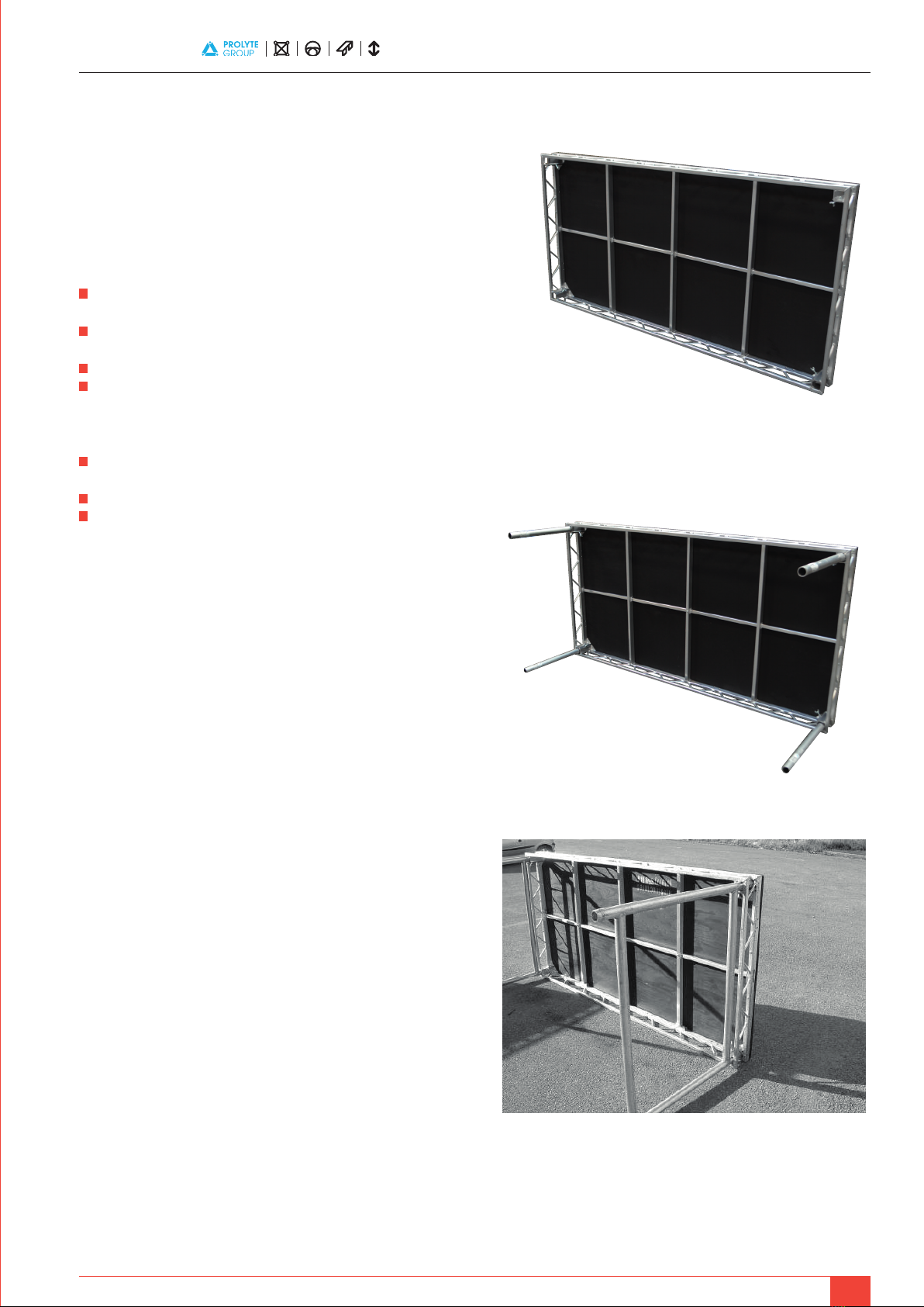
Longest Edge on the floor
The Legs or Leg Frames should be inserted into the clamps below the deck
and tightened by hand using the wing bolts supplied in each deck:
(Using 545mm Legs)
(Using 1115mm Leg Frames)
1. LITEDECK INSTALLATION
To ensure the health and safety of workers, the following guidelines should be
observed.
GENERAL
Protective clothing may be worn whilst on site.
• Gloves should be worn to protect hands against Aluminium and
rough edges.
• The weight and size of the LiteDeck components should be considered
when transporting and carrying.
• Any other site regulations for particular sites should be adhered to.
• Workers should be adequately trained in the use of tools
mentioned below.
TOOLS NEEDED
• 8mm Allen Key, preferably c/w decent sized handle
(For locking decks together).
• 2 x 17mm Spanners (For tightening deck bolts together)
• 2 x 19mm Spanners (For tightening Handrail / brace bolts together)
THE OUTLINE PROCESS
The following list provides a step-by-step outline process showing how to
build the stage and add the various different components together. For each
of the separate components, there is a set safety procedure, see the relevant
sections in this package.
1. Assess the ground conditions. The ground must be firm
and level before beginning.
2. By measurement, determine the rear edge of the finished stage
to be a starting point.
3. Assemble the first deck (See section 1)
4. Assemble other decks and fasten together (See section 2)
5. Add bracing between leg frames. (If leg frames are used)
6. Fix the hand rails around the sides of the decks (See section 3)
7. Assemble the modular step units (See section 4)
8. Fix the steps to the stage side.
9. Assemble the appropriate ramps (See section 5)
10. Fix the top of the ramp to the deck using bolts.
11. Apply white / yellow tape to any exposed edge of the stage,
ramps and steps.
12. Dress the edges of the stage if required (eg. Skirting)
13. If any electrical equipment is used on stage, the structure should be
earth bonded.
SECTION 1 – ASSEMBLING THE FIRST DECK
Each LiteDeck should be carried into place (consider size and weight) and
placed on the ground, balancing on its longest edge. See Below:
LiteDeck User Installation Guidance
4
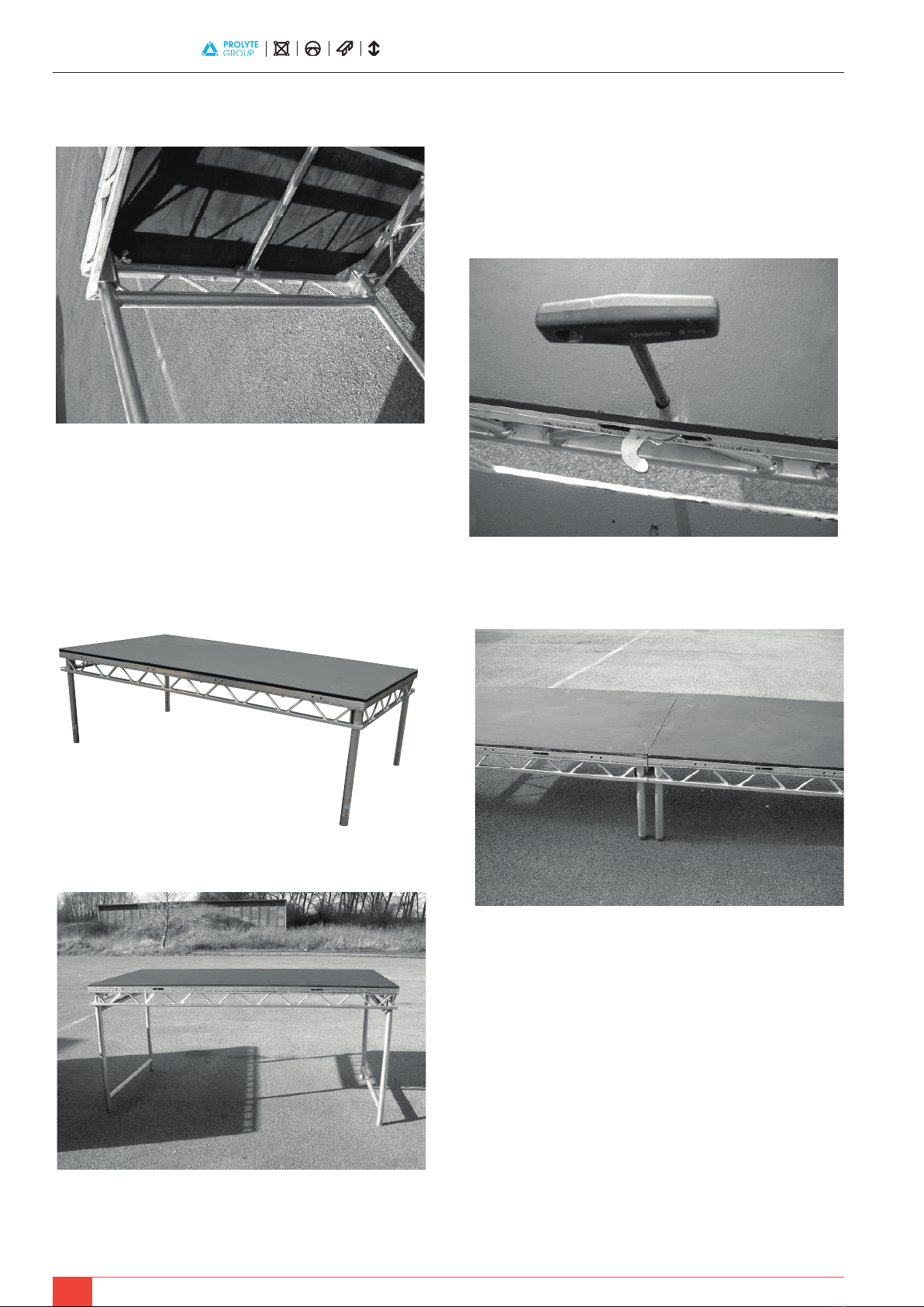
SECTION 2 – ASSEMBLING THE OTHER DECKS
AND FIXING TOGETHER
All the other LiteDeck units should be assembled in the same manner as
above. Assemble one at a time and attach it to the existing deck, see below:
This picture shows the Coffin Lock system being used. The two decks are
brought together, then using the 8mm Allen Key are locked tight. The hook
inside the lock is rotated from above by hand.
(570mm Deck Height)
Tighten the Wing Bolts by hand
Ensure the leg is pushed all theway to the top of the socket
Once the legs / frames are firmly in place, the deck should be placed upright,
again, consider the size and weight of the deck. See Below:
(570mm Deck Height)
(1140mm Deck Height)

LiteDeck User Installation Guidance
5
(Bolt is used to join the handrails)
(Completed Handrails)
(1140mm Deck Height)
At the deck height of 1140mm, only one brace per pair of leg frames is
needed, see drawing below:
SECTION 3 – FIXING HAND RAILS TO THE SIDE OF
THE DECKS
The standard handrail used is the open handrail and is attached to the outer
side of the deck using bolts. One person holds the handrail in line with the
holes whilst another inserts the bolts and tightens them. See Below:
(The holes are lined up and bolts inserted)
NOTICE
THE INSTALLATION OF HANDRAILS IS THE SAME FOR BOTH HEIGHTS OF
DECKS
LiteDeck User Installation Guidance
6
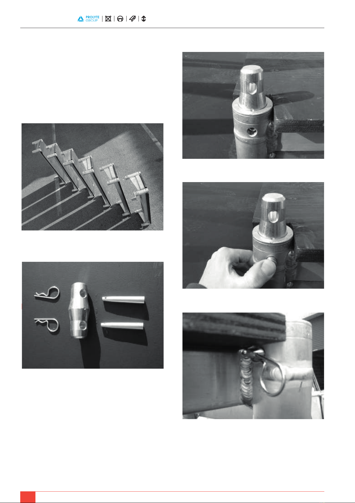
SECTION 4 – ASSEMBLING THE MODULAR STEP UNIT
The modular steps are designed to be 190mm high units and in combinations
can be used for stages of any height. The illustration used here will show a 6-
step unit, which is the correct height for the 1140mm high stage.again,
consider the size and weight of the deck. See Below:
The separate units are laid out in the order they are to be assembled
The step units are joined using conical spigots, pins and clips, the process is
as follows:
(Spigot placed in socket)
(Pin pushed in by hand)
(‘R’ Clip placed through hole)
LiteDeck User Installation Guidance
7
This picture shows the components used to join the units. From the left – ‘R’
Clips, Conical Spigot and Pins.
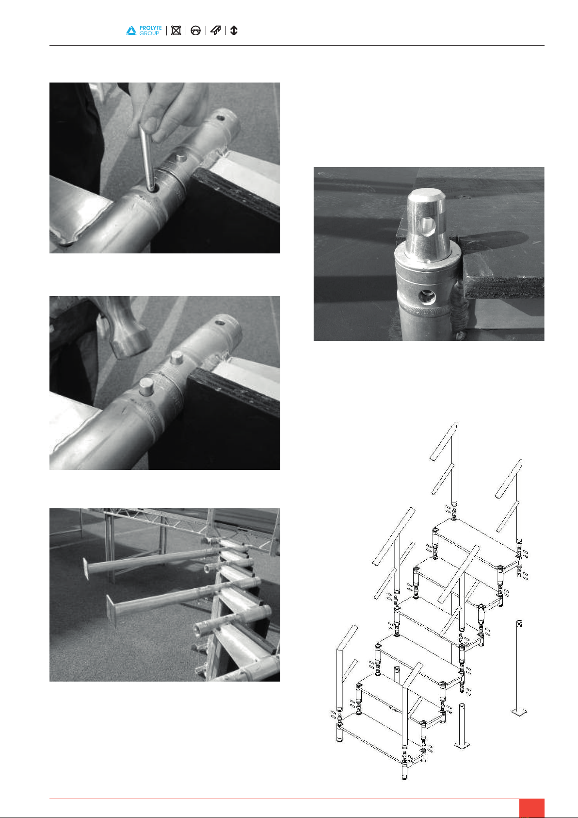
IMPORTANT: When inserting the conical spigot into the socket, the
pigot must face the correct way. The spigot has an indent on one side
that must face the outside of the deck, see picture below:
Small indent, indicating the correct way round. (The indent points to the
outside)
This drawing shows a breakdown of all the components used in the modular
step system for a six-step unit.
(Units are joined together)
(Pins hammered in to tighten)
(Every third step, a support leg should be used)

LiteDeck User Installation Guidance
8
Once the step unit is fully constructed, it can be fastened to the existing stage.
The top step uses a hook system as can be seen below:
(Hooks through the Deck lacing)
(The six-step unit attached to the stage)
ASSEMBLING THE MODULAR STEP UNITS
1. Determine the amount of step units required for the finished height of the
stage.
2. Gather all necessary components and check for any damage to pins /
clips before use.
3. Lay the step units on the ground in the order they are to be connected,
and ensure that the top back section of the step unit has a conical spigot
included on both sides.
4. The spigots are inserted into the socket with the small indent facing
towards the outside edge of the deck, the pin is then inserted into the
hole from the outside by hand and the ‘R’ clip placed through the hole in
the end of the pin to stop the pin sliding out.
5. The top of each modular step now needs to be joined to the bottom of
the next, this is done in the same manner as above but uses the conical
spigot as the joint. Once both pins are in place by hand, they should be
then hammered tightly into place.
6. This process should be repeated for the amount of units used.
7. The support legs should now be fitted to the underside of the step units,
again this uses the same system with the conical spigots. One support
leg should be fitted every second or third step.
8. If possible the top step of the unit should be attached to the side of the
stage decks using the angle hooked over the lacing.
9. The handrails should now be attached to the tops of the steps, again
using the conical spigot system. The handrails are also modular in design
and the correct amount of sections should be connected together using
the expanding spigots.that must face the outside of the deck, see picture
below:
SECTION 5 ASSEMBLE THE APPROPRIATE RAMPS
This installation uses custom designed ramps, please refer to the following
drawings and method statement.
Ramps #1 (for 570mm Deck Height Stage)
Ramps #2 (for 570mm Deck Height Stage)
COMPONENT LIST:
2 – 8’x4’ LiteDeck
1 – Ramp Infill #1 Label – Ramp Infill#1
1 – Ramp End #1 Label – Ramp End#1
2 – Scaff Legs 167mm (D) 2 – Scaff Legs 167mm (D)
2 – Scaff Legs 350mm (C) Label – R1 (C)
2 – Scaff Legs 357mm (B) Label – R1 (B)
2 – Scaff Legs 541mm (A) Label – R1 (A)
COMPONENT LIST:
1 – 8’x4’ LiteDeck
1 – 4’x4’ LiteDeck Label – Ramp Infill#2
1 – Ramp Infill #2 Label – Ramp End#2
1 – Ramp End #2 Label – R2 (D)
2 – Scaff Legs 177mm (D) Label – R2 (C)
2 – Scaff Legs 291mm (C) Label – R2 (B)
2 – Scaff Legs 301mm (B) Label – R2 (A)
LiteDeck User Installation Guidance
9
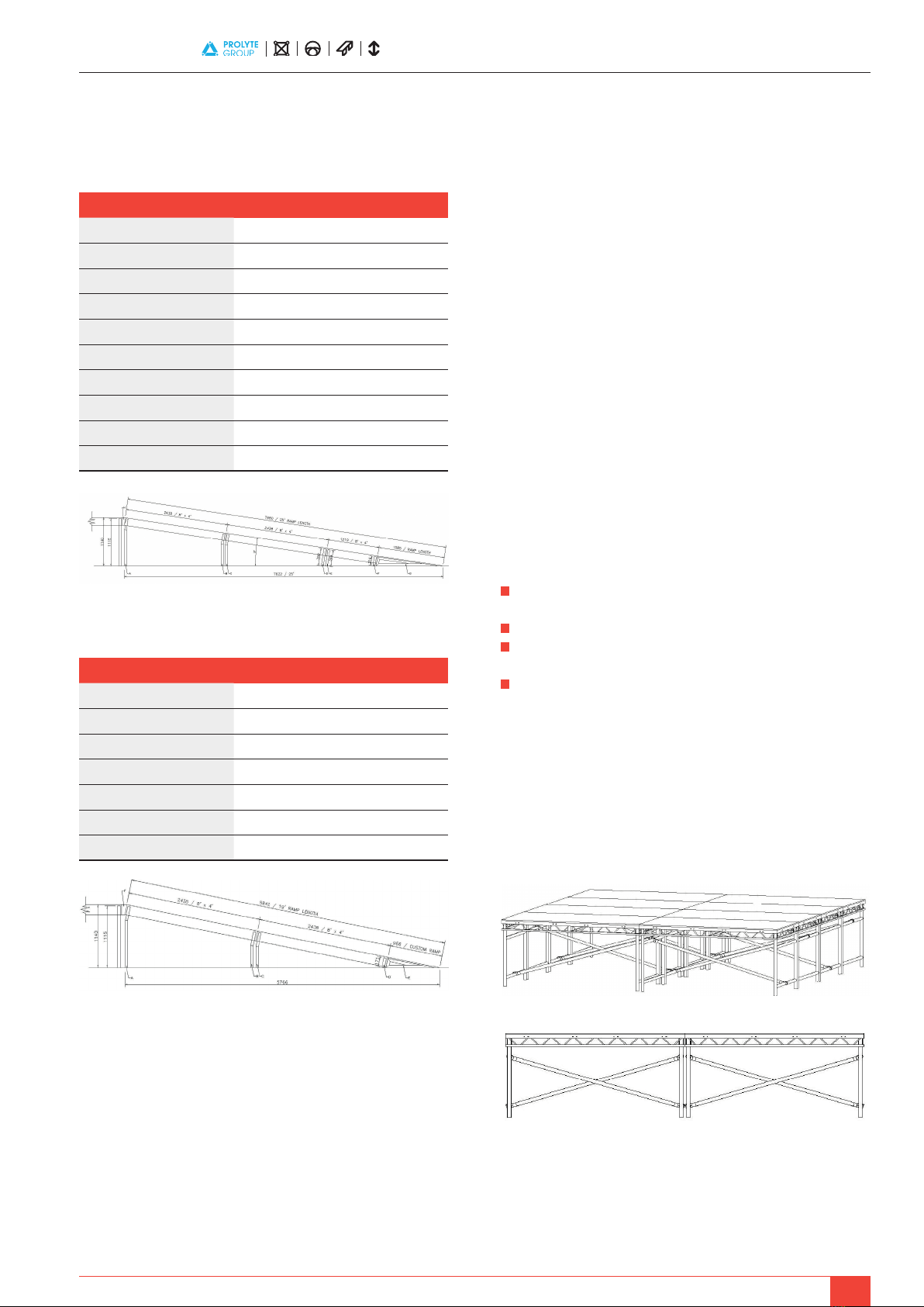
Ramps #3 (for 1140mm Deck Height Stage)
Ramps #4 (for 1140mm Deck Height Stage)
Installation of Ramps to the Existing Stage
1. Determine the position on the side of the stage where the ramp will
attach and ensure that the appropriate handrail is removed.
2. Gather all the components for the ramp, checking dimensions / sizes
from the list.
3. Assemble the highest part of the ramp first by inserting the correct leg
frames in the ends of the LiteDeck and with one person at each end, lift
the deck upright.
4. The highest deck should be positioned against the stage but allowing
enough room for the relevant infill to be attached.
5. The infill should be first bolted to the existing stage using M10 x 70mm
Bolts, then the other side bolted to the highest deck of the ramp.
6. Each lower section of the ramp can now be added in the same manner
as point (3) and locked to the next deck either by the coffin lock or bolts.
7. At the end of the ramp, a special custom made ramp end is used, this
should be placed against the last deck and bolted to it using
M10 x 70mm Bolts.
8. Once the ramp surface is complete, the handrails should be fitted. The
correct handrail is held in place with its legs hovering over the holes in
the side of the deck and then bolted on using M10 x 120mm bolts.
9. The handrails can then be bolted together using the holes in the sides
with M10 x 120mm bolts.
10. Finally, depending upon the use of the ramp, the decks maybe painted
using non-slip paint. This can be applied using a roller or brush.
Dismantling of Ramps from Existing Stage
1. The bolts and coffin locks connecting all components should be removed
using appropriate tools.
2. The various parts of the ramp should be dismantled (reverse procedure to
point (3).
3. The components should be checked for any damage.
4. All components should be packed away and stored on relevant dolly’s
safely.
LITEDECK TECHNICAL INFORMATION
The LiteDeck is constructed from Aluminium structural grade alloy for the
sub frame and ¾” plywood for the decking surface.
A typical 8’ x 4’ section of LiteDeck weighs 54kg
The LiteDeck platform is designed to be incorporated into stage settings
and to carry a udl (uniformly distributed load) of 5kN/m²
For further information regarding staging regulations, please refer to the
following publication: Temporary Demountable Structures The Institute of
Structural Engineers (1999) 2nd Ed.
Notes on Good Practice
It is important that any damage caused to the LiteDeck during use or transport
be assessed by a competent person before use and if necessary repaired or
replaced to avoid failure.
When using braces between the leg frames of decks, each brace should
alternate in angle, see below:
COMPONENT LIST:
2 – 8’x4’ LiteDeck
1 – Ramp Infill #4 Label – Ramp Infill#4
1 – Ramp End #4 Label – Ramp End#4
2 – Scaff Legs 171mm (D) Label – R4 (D)
1 – Leg Frame 633mm High (C) Label – R4 (C)
1 – Leg Frame 652mm High (B) Label – R4 (B)
1 – Leg Frame 1107mm High (A) Label – R4 (A)
COMPONENT LIST:
2 – 8’x4’ LiteDeck
1 – 4’x4’ LiteDeck
1 – Ramp Infill #3 Label – Ramp Infill#3
1 – Ramp End #3 Label – Ramp End#3
2 – Scaff Legs 216mm (F) Label – R3 (F)
2 – Scaff Legs 384mm (E) Label – R3 (E)
2 – Scaff Legs 399mm (D) Label – R3 (D)
1 – Leg Frame 748mm High (C) Label – R3 (C)
1 – Leg Frame 763mm High (B) Label – R3 (B)
1 – Leg Frame 1115mm High (A) Label – R3 (A)

LiteDeck User Installation Guidance
10
WWW.PROLYTE.COM FACEBOOK.COM/PROLYTEGROUP TWITTER.COM/PROLYTE
Table of contents


