PROMA REHA GENEO User manual

PROMA REHA, s.r.o.,
Riegrova 342, CZ-55203
Česká Skalice, tel.: +420 491 11 22 33, fax: +420 491 54 11 85,
Company ID: 63219107; Tax ID: CZ63219107,
info@promareha.cz, www.promareha.cz, registered in the
Commercial Register held with the Regional Court in Hradec
Králové, section C, entry 7945
we are authorised to use the above-mentioned trademarks
ver. 21-1
23/04/2021
GENEO
Hospital bed for standard care
GRANO
Care bed for standard care
INSTRUCTIONS

Instructions for Use of GENEO and GRANO Beds
Page 2/40
Dear Client,
Thank you for purchasing the product of our company. PROMA REHA, s.r.o. is a leading manufacturer of medical
equipment for hospitals, rest homes and other health centres operating on the Czech and foreign markets for more than 25
years. The products of PROMA REHA, s.r.o. are known due to their modern light structures, which, despite their low weight,
achieve state-of-the-art parameters, strength and utility reliability. Precise surface finish, thought-out construction and
production technology, associated with the cutting-edge treatment of all surfaces, provide the products with long service life.
We therefore firmly believe that the purchased product will serve you for a long time and to your absolute satisfaction. To
achieve this under all operating conditions, we would like to ask you to read thoroughly and observe the following safety,
operation, utility and service instructions. In case of any difficulty or uncertainty, please contact our technical department at
the address below or our sales representative who has facilitated the purchase of our product. You can also obtain the
necessary information regarding spare parts deliveries, service intervention options, repairs or periodic safety-technical
inspections. Further up-to-date information about the company, its products, services and special offers can also be obtained
on www.promareha.cz.
Customer Department: (+420) 491 11 22 33, info@promareha.cz
We wish you carefree use of the purchased product, your
PROMA REHA, s.r.o.

Instructions for Use of GENEO and GRANO Beds
Page 3/40
TABLE OF CONTENTS
Introduction ...................................................................................................................................................................................5
Method of Delivery .......................................................................................................................................................................6
Safety Instructions.........................................................................................................................................................................6
Conditions of Use..........................................................................................................................................................................7
Technical Parameters..................................................................................................................................................................... 7
Bed Placement...............................................................................................................................................................................8
Bed Description............................................................................................................................................................................. 9
Installation and Commissioning of the Bed.................................................................................................................................10
Relocation and Handling ............................................................................................................................................................. 11
9.1 Switching Off - the bed with the nurse panel ....................................................................................................................... 11
9.2 Switching Off - the bed with the patient controller .............................................................................................................. 11
9.3 Switching On the Bed........................................................................................................................................................... 11
Electrical Control Elements – General Operating Instructions.................................................................................................... 12
10.1 Nurse Panel Onimed............................................................................................................................................................. 12
GO Button.............................................................................................................................................................. 13
STOP Button.......................................................................................................................................................... 13
Standard Adjustment.............................................................................................................................................. 13
One-Button Positions ............................................................................................................................................. 13
Function Lock Using the Nurse Panel.................................................................................................................... 14
10.2 Nurse Panel Linak ................................................................................................................................................................ 14
GO Button.............................................................................................................................................................. 14
STOP Button.......................................................................................................................................................... 14
Standard Adjustment.............................................................................................................................................. 15
One-Button Positions ............................................................................................................................................. 15
Function Lock Using the Nurse Panel.................................................................................................................... 15
10.3 Patient Hand Controller with Illumination ........................................................................................................................... 16
Function Lock of the Patient Controller................................................................................................................. 16
Trendelenburg/Anti-Trendelenburg ....................................................................................................................... 17
Controllers Integrated in Siderails.......................................................................................................................... 18
10.5 Function of Patient Mobilisation .......................................................................................................................................... 19
10.6 Satellite Patient Controller ................................................................................................................................................... 20
10.7 Chassis Illumination ............................................................................................................................................................. 20
10.8 Lowered Position of the Bearing Area .................................................................................................................................21
10.9 Standby Battery.................................................................................................................................................................... 21
10.10 Clamp for Electrical Potential Balancing ............................................................................................................................. 21
10.11 Power Supply Cable Holder ................................................................................................................................................. 22
Mechanical Control Elements...................................................................................................................................................... 22
11.1 Central Brake........................................................................................................................................................................ 22
11.2 Automatic Safety Brake ....................................................................................................................................................... 22
11.3 Mechanical Positioning of the Calf Part............................................................................................................................... 23
11.4 CPR - Quick release of the back part ................................................................................................................................... 23
11.5 Bed Extension....................................................................................................................................................................... 24
Headboard, Footboard and Siderails............................................................................................................................................ 25

Instructions for Use of GENEO and GRANO Beds
Page 4/40
12.1 Removable Tiltable Siderails ............................................................................................................................................... 25
12.2 Removable Headboard and Footboard .................................................................................................................................26
12.3 UNI Siderails........................................................................................................................................................................ 26
12.4 Plastic Tiltable Siderails....................................................................................................................................................... 27
Other Parts of the Bed .................................................................................................................................................................28
13.1 Bearing Area ........................................................................................................................................................................ 28
13.2 Universal Holders of Accessories......................................................................................................................................... 28
13.3 Impact Wheels...................................................................................................................................................................... 28
Accessories.................................................................................................................................................................................. 29
14.1 Trapeze Bar with a Small Bar .............................................................................................................................................. 29
14.2 Infusion Stand....................................................................................................................................................................... 29
14.3 Accessory Holders “Eurobars”............................................................................................................................................. 30
14.4 Stacking Rack for Bedding................................................................................................................................................... 30
Problems and Their Troubleshooting .......................................................................................................................................... 31
15.1 The buttons on the Patient Hand Controller are Flashing..................................................................................................... 31
15.2 Non-Functional Bed– does not emit light, does not respond to the control.......................................................................... 31
15.3 Non-Functional Bed – emits light, does not respond to the control ..................................................................................... 31
15.4 Error Message – the diodes flash on the controller .............................................................................................................. 32
Motor Overloaded.................................................................................................................................................. 32
Motor Not Connected............................................................................................................................................. 32
Position Error......................................................................................................................................................... 33
IRC Sensor Error.................................................................................................................................................... 33
Cleaning....................................................................................................................................................................................... 33
Storage......................................................................................................................................................................................... 34
Maintenance and Service............................................................................................................................................................. 35
Warranty...................................................................................................................................................................................... 35
Product Disposal.......................................................................................................................................................................... 36
Abbreviations, Signs and Symbols Used..................................................................................................................................... 37
21.1 Bed manufacturing label....................................................................................................................................................... 38
Package Contents......................................................................................................................................................................... 38
List of Supported Accessories..................................................................................................................................................... 38
Contact......................................................................................................................................................................................... 38

Instructions for Use of GENEO and GRANO Beds
Page 5/40
INTRODUCTION
These Instructions for Use are designated for the beds of GENEO and GRANO type.
The user must read these Instructions before handling of the bed for the first time.
The user is obligated to operate the bed according to these Instructions for Use.
Actions performed at variance with the Instructions for Use may cause damage to the bed, damage to the health of a
patient, operator or third party. In such case, the manufacturer waives responsibility for damage caused!
The Instructions for Use must be available for the whole service life of the bed!
The manufacturer reserves the right to change the contents of these Instructions for Use related to the technical
parameters and adjustments of the bed!
Use of the GENEO type beds
-emergency care provided in a hospital or other healthcare facility where health supervision and monitoring are required and
where medical electrical devices are often used to maintain or improve the patient’s condition,
long-term care in the medical facility where health supervision is required and, if necessary, monitoring is carried out and
medical electrical devices may be used to assist in medical procedures to maintain or improve the patient's condition.
Use of GRANO type beds
-intensive/critical care provided in a hospital where health supervision and continuous monitoring during 24 hours are required
and where provision of life support systems/devices used in medical interventions is necessary to maintain or improve the
patient's vital functions
emergency care provided in a hospital or other healthcare facility where health supervision and monitoring are required and
where medical electrical devices are often used to maintain or improve the patient’s condition
The bed is intended for the handling of one lying person!
The bed must never be used to lift materials, loads or other persons.
The bed must not be positioned or lifted to the positions which, with regard to the patient’s condition, could cause
bodily harm or could endanger the patient’s life!
The bed may be operated by a medical staff who has been thoroughly familiarised with these Instructions for Use.
The partial function of the bed may be used by the patient instructed by health care staff!
The bed must not be operated by persons under the age of 12 without the supervision of an adult!
If the bed is not used, it must remain braked and in the basic position (i.e. the bearing area and all the adjustable
parts are in the lowest possible position)!
If the patient is not under supervision, the bed must be braked and kept in the lowest position in order to reduce the
risk of injury due to falling out of the bed!
In such case, a patient can be a designated attendant here. If the product is equipped with a patient controller, the
patient can control some of the basic functions, such as the adjustment of the position of: back part, thigh part, calf
part; the adjustment of the bearing area height, the auto contour position, the cardiac chair, the Anti-Tendelenburg
function and the position of getting out. All of these functions can be arrested so that the patient cannot change the
function which is hazardous due to his/her state of health. All other functions of the bed are designated for a
professionally trained person.
The pictures used further in the Instructions for Use are illustrative and do not necessarily match the purchased bed!
The manufacturer is authorised to manufacture the products of this type on the basis of the "Permission to Manufacture and Distribute
Medical Devices" granted by the Ministry of Health of the Czech Republic Ref. No. FAR-742-25.4.1995 733/8.
The manufacturer operates according to certified quality management systems in accordance with the following standards:
ČSN EN ISO 9001:2016
ČSN EN ISO 13485 ed.2:2016
ČSN EN ISO 14001:2016
The bed complies with international standards:
ČSN EN 60601-1
ČSN EN 60601-1-2
ČSN EN 60601-2-52
ČSN EN 60601-1-6
ČSN EN ISO 14971
ČSN EN 1041
ČSN EN ISO 15223-1

Instructions for Use of GENEO and GRANO Beds
Page 6/40
METHOD OF DELIVERY
The bed is delivered assembled and ready for use. The accessories are supplied separately with the necessary fastening material to
be attached to the bed. Upon delivery, the entire content of the delivery must be checked according to the delivery note.
Any defects, damage or deficiencies must be immediately notified in writing to the carrier and the manufacturer!
Check the completeness of the delivery and its condition according to the delivery note. Record any deficiencies in
the delivery or transport note and hand them over to the seller in writing!
SAFETY INSTRUCTIONS
Before using the bed, it is necessary to familiarize yourself with the Instructions for Use and
carry out the operation only in accordance with them!
The bed may only be operated by the persons who are familiar with the Instructions for Use in
detail!
The bed must not be used, if it is not in perfect condition, especially if there were found the
defects that could harm a patient, operating personnel or damage the bed
Use the bed only in the interior and on flat floors!
The bed must not be overloaded!
The bed is intended for one patient only!
In case of oversize patients, it is necessary to pay increased attention to the adjustment of positions - there is a risk
of injury
The bed may only be used with an electric socket for which it is intended!
When a patient remains unsupervised by health care personnel, set the bed to the lowest position and brake it!
According to the decision of the health care professional, partial bed functions may be used by the patient after
thorough training by the health care professional!
The bed must always be properly braked apart from its relocation. Medical staff must always make sure that the
bed is braked before use. If the bed is not braked, there may exist an increased risk of injury when the bed starts
moving spontaneously, mainly when getting up of the bed, seating on the bed or leaning against it!
The bed with a patient may be moved only at the lowest position of the bearing area and with both siderails lifted to
increase patient’s safety.
Before handling the siderails, make sure that there is no risk of injury to the patient or damage to other objects due
to squeezing in the moving parts or falling out of the bed!
When adjusting the bearing area height, there must be no objects between the bed frame and the chassis (ground) –
they could be damaged or the operator or a third party may be injured!
When adjusting the back or foot part, there must not be any objects between the bed frame, the headboard and the
back or foot part – they could be damaged or the patient, the operator or a third party may be injured!
Adjusting to the special Trendelenburg and Anti-Trendelenburg positions may only be carried out by healthcare
professionals!
Before adjusting to the Anti-Trendelenburg position, insert the bedding rack into the bed - in the basic position!
The power network cable must always be routed in such a way to avoid its damage due to winding around the moving
parts or pressing between them - there is a serious risk of electric shock!
Service interventions must only be performed by a service centre authorized by the manufacturer and using original
spare parts!
Risk of injury to a patient, operator, third party or damage to the surrounding equipment may arise mainly from:
-unauthorized use,
-a careless procedure when adjusting the back or foot part position,
-a careless procedure, when adjusting the height of the bearing area,
-adjusting the bed with the patient to special positions – especially TR, ATR,
-operating the bed on the surface for which it is not intended,
-maintenance in an unauthorised manner or by an unauthorised person,
-wrong laying a patient on the bed (the patient's head in the area of the legs)
-when using a specific mattress intended to achieve a prophylactic or therapeutic effect!
The bed is powered from the electrical network and can therefore interfere with extremely sensitive devices. During
the development of the bed, the utmost was done to minimize the risk of adverse electromagnetic influences. The
bed is manufactured in full compliance with harmonised standard EN 60601-1-2. When using the bed in full
compliance with the Instructions for Use, you can avoid any problems!

Instructions for Use of GENEO and GRANO Beds
Page 7/40
CONDITIONS OF USE
The bed may only be used in the interior with the ambient temperature ranging between +10°C and +40°C, the relative
humidity between 30% and 75% and the atmospheric pressure between 700 hPa and 1060 hPa.
The bed is not intended for wet and explosive environments.
TECHNICAL PARAMETERS
All beds are made of quality steel profiles, which are subsequently surface-treated with baking varnishes, zinc or chromium layer.
The beds are also supplemented with metal, plastic or wooden sheathing in various designs and types. Furthermore, the beds may
differ in the width of the bearing area and other special functions (extension of the bearing area, pulling headboard and footboard,
special functions of the Trendelenburg and Anti-Trendelenburg positions.
GENEO GRANO
Bearing area length 200 cm 200 cm
Bearing area width 90 cm 90 cm
Outer bed width (with boards) 99.5 cm ±5 mm P, K, E - 99.5 cm * ±5 mm
Outer length of the bed (with boards) 220 cm ±5 mm P - 210 cm; K - 211 cm; E - 215 cm ** ±5 mm
Bearing area height 40-85 cm / ±5 mm 40-85 cm ±5 mm
Bearing area extension 1 x 30 cm -
Mattress thickness, when used under normal conditions 14 cm 14 cm
Recommended minimum mattress thickness 12 cm 12 cm
Recommended maximum mattress thickness 22 cm 16 cm
Recommended mattress size 90 x 200 cm 90 x 200 cm
Weight 125 kg (according to configuration) 125 kg
Safe operating load of the bed 270 kg 270 kg
Maximum patient weight 235 kg 235 kg
(205 kg for application environment 2)
The bed is intended for application environment 2, 3 1,2
Max. angles of adjustable parts: back 72° ±2° 72° ±2°
thigh 40° ±2° 40° ±2°
calf 25° ± 2° 25° ± 2°
TR/ATR angle 16° / 16° / ±1° 16° / 16° / ±1°
Length of the bearing area parts
Back part 78.5 cm 78.5 cm
Pelvic part 20 cm 20 cm
Thigh part 29 cm 29 cm
Calf part 52 cm 52 cm
* Width with impact wheel dimensions + 3 cm
** Length with impact wheel dimensions P,K + 7 cm / E + 5 cm
Instructions for Use of GENEO and GRANO Beds
Page 8/40
Where a specific mattress intended to achieve a prophylactic or therapeutic effect is used, it is possible to use the
mattresses up to the height of 26 cm. In this case, there may be an increased risk of the patient falling out of the bed.
Pay special attention when positioning the bearing area to the special positions!
In case of the beds intended for emergency care provided in a hospital or other healthcare facility where health
supervision and monitoring are required and where medical electrical devices are often used to maintain or improve
the patient’s condition, due to the higher weight of accessories the patient’s maximum weight is reduced to 205 kg!
Parameters of electrical parts used on the bed, Onimed
Operating voltage 230 V
Supply frequency 50/60 Hz
Maximum input 350 W
Protection class I II
Applied part B type
Protection minimum IPS4
Motor load 10%, 2 min. max. load/18min. in rest
Nominal value of fuse 5 A
Weighted level of noise acoustic power 48 dB measured according to ISO 3746, not loaded
Parameters of electrical parts used on the bed, Linak
Working voltage 100 - 240 V
Supply frequency 50/60 Hz
Current 2.5 A
Protection class II
Applied part B type
Protection minimum IPX6
Motor load 10%, 2 min. max. load/18min. in rest
BED PLACEMENT
The bed should be placed in such a way that there is at least 40 cm of free space around it on each side. Furthermore, make sure that
no items, such as shelves, televisions, etc., are placed above the bed, which could be released or pulled down by the bed when
adjusting its position or lifting it and it could therefore result in the injury to the operator or the patient! If the bed is equipped with
accessories (e.g. trapeze bar, infusion stand, extension kit, etc.), the operator controlling the bed must ensure that none of the parts
of the bed or accessories touches, leans against or otherwise contacts the ceiling, niches or other fixed or removable objects placed
on the walls or dropped ceilings, such as shelves, lamps, etc. If there is not enough space for such handling, remove the accessories
or place the bed on another place, so that it does not come into contact with other objects.
If the bed is equipped with tilting of the bearing area to the special Trendelenburg or Anti-Trendelenburg positions, it must always
be located so that it does not collide with the surrounding objects in any of these positions. When using these positions, always
monitor the trajectory of the accessory placed on the bed. The trapeze bar with a small vertical bar, the infusion stand or the extension
kit in the above-mentioned extreme positions exceed the contour of the bed. They could cause damage to the surrounding objects or
injury to a third party!
Always place the bed in such a way that there is at least 5 cm free space on each side of it. When adjusting the bearing
area height, it may be deflected. If the bed is placed close to the surrounding objects (walls), it could be damaged, or
it could damage the surrounding things or cause bodily harm to the patient, the operator or a third party!
If the bed is equipped with Trendelenburg, Anti-Trendelenburg positions, place it so that the bed does not collide
with the surrounding objects in both extreme positions!
If the bed is fitted with the accessories (trapeze bar with a small vertical bar, infusion stand, etc.), observe the
accessories trajectory each time the bed is adjusted because in the Trendelenburg and Anti-Trendelenburg positions,
the accessories substantially exceed the bed contour!
Instructions for Use of GENEO and GRANO Beds
Page 9/40
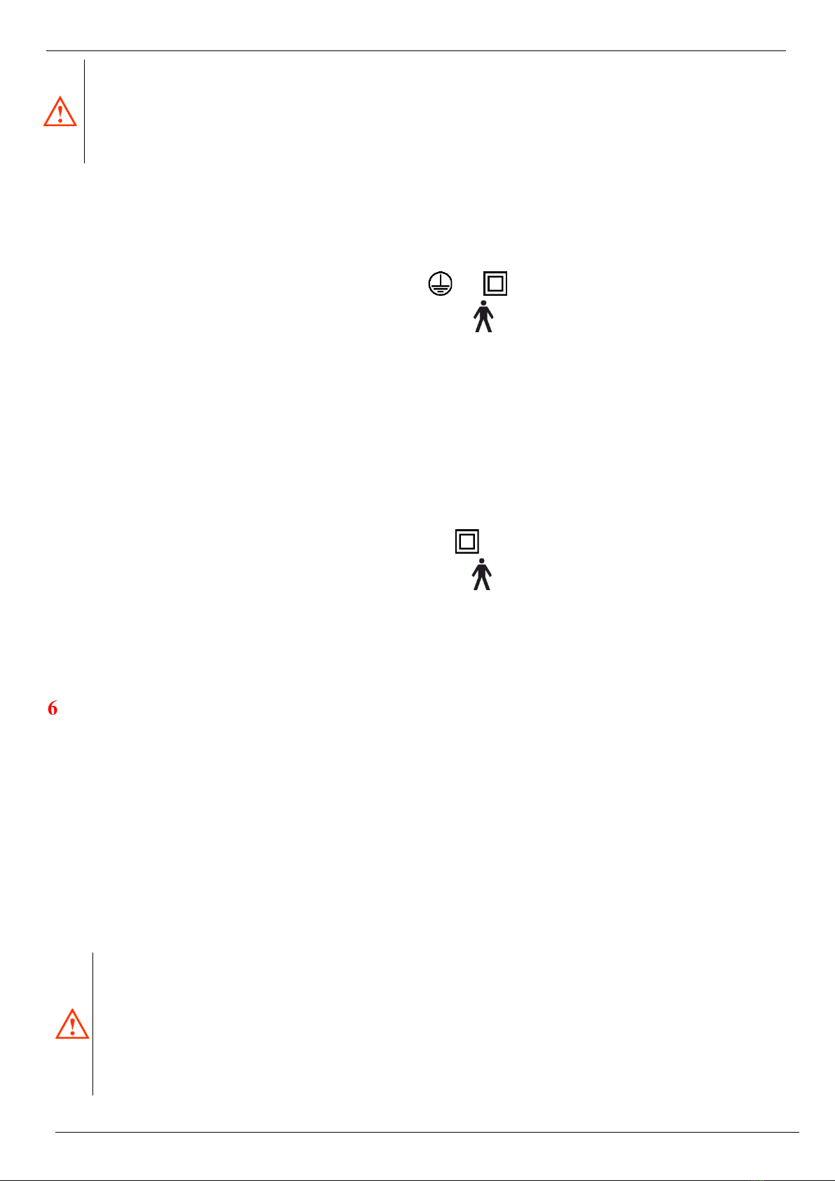
BED DESCRIPTION
1) Universal accessory holder
9) Calf part
17) Board lock
2) Headboard
10) Footboard
18) Bedding rack
3) CPR
11) Impact wheel
19) Nurse panel
4) Mattress holder
12) Caster
20) UNI Siderails
5) Back part
13) Stainless ‘Eurobar’
21) UNI siderail lock
6) Thigh part
14) Tiltable siderail control
7) Tiltable siderail
15) Central brake lever
8) Patient manual controller
16) Bearing area extension
1
2
3
4
5
6
7
8
9
10
11
12
13
14
15
16
17
18
19
1
2
3
5
6
21
8
9
10
12
15
16
18
19
20
Instructions for Use of GENEO and GRANO Beds
Page 10/40
INSTALLATION AND COMMISSIONING OF THE BED
This chapter lists the basic tasks that must be fully performed before the bed is put into operation for the first time!
•Consult the Instructions for Use thoroughly.
•Remove all packaging material from the bed and dispose of it in an environmentally friendly way
•Check the completeness of the delivery and its condition according to the delivery note. Record any deficiencies in
the copy of the delivery or transport note and send them in writing to the manufacturer or dealer.
•Leave the bed to adapt to the ambient temperature
If the bed is free from all packaging and fixation elements, leave it without the mattress and bedding for at least two hours the room
where it will be used. This step is essential for adapting the temperatures of the individual parts of the bed to the environment in
which it will be used. If vapours are condensed on the bed structure, leave the bed at rest until the last traces of condensate disappear
from its structure.
•While the temperature is balancing, read the COMPLETE Instructions
for Use thoroughly.
•Never perform the performance test before studying the entire
Instructions for Use.
•If the accessories are included in the delivery, install them according to
the Instructions for Use.
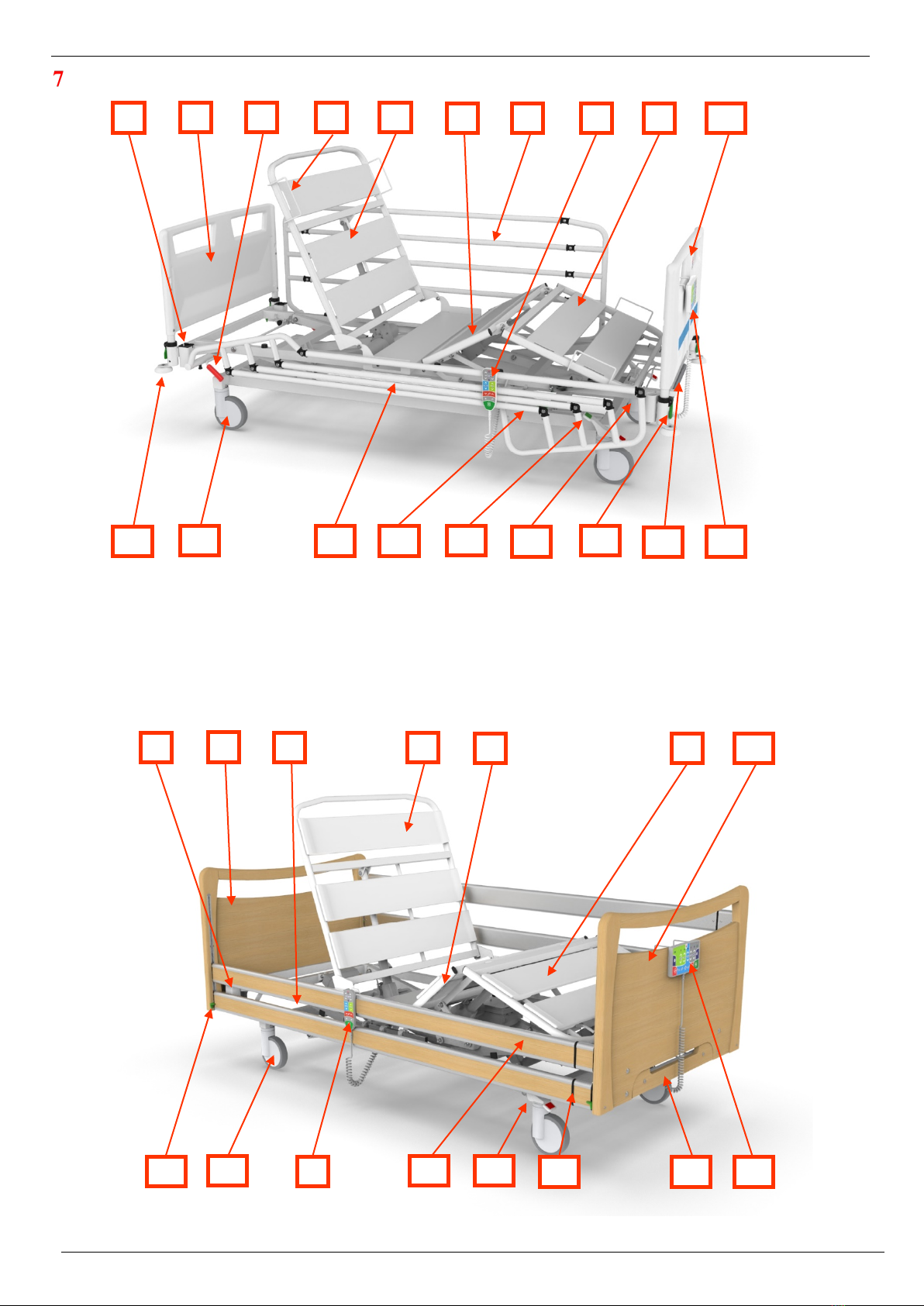
•If the GRANO bed is delivered with the lift of the bearing area up to 25
(27) cm, install the automatic brake on the central brake control, which is
part of the package:
-Lift the bed using the controller
-Screw the plastic rose button (2) on the outside of the central trapeze bar
(1), see figure
-Carefully tighten the plastic rose button
•Test the functionality of the individual parts of the bed according to the
Instructions for Use
WARNING! The power supply cable for the drive of the bed must not be connected to doubles, similar hubs, extension cables with
one or more sockets, which are not approved for use in the country of use, and which do not have an appliance input power of at least
1000 W. None of the supply cables may be led in such a way that they can be pinched, broken or otherwise damaged when the bed
and its parts are moving!
Insert the power supply cable plug into the 230V/50-60Hz power network socket. After insertion, the bed must not emit any sound
and must not move spontaneously. If that happens, immediately disconnect the power supply cable of the bed from the power supply
and contact an authorized service or supplier. When the plug is inserted into the network socket, the backup battery of the bed starts
to charge automatically. On the nurse panel display or patient controller, the LED diode indicating the connection of the bed to the
power network goes on as well as the pictogram indicating the charging of the backup battery. If the bed was out of service for a
long time before being connected to the network and the backup battery is completely discharged, let the bed fully charge. Fully
discharged backup batteries may not allow full parallel positioning of all parts of the bed, and if the backup battery is very low, joint
motion of multiple motors may be phased into the sequence of partial movements.
If the backup battery is charged, use all kinds of controllers in the sequence of the nurse panel, patient controller and satellite
controller, gradually test the adjustment of all bed parts as described below in these Instructions for Use. If the movable parts of the
bed do not start to move within five seconds, or if you hear that the bed motors work excessively, stop positioning and disconnect
the bed power supply cable from the power supply. Check if there is no packaging material left on the bed that could cause non-
standard behaviour or if the nurse panel or some of its functions are not locked. If necessary, unlock these functions, see Chapter
10.2, Nurse Panel. If no cause of malfunction is found on the bed, contact the authorised service centre or manufacturer. If the bed is
not working properly repeatedly, contact the service centre. If the initial test of positioning takes place without any problems, you
can start using the bed.
Keep the Instructions for Use safe
In case of any malfunction, disconnect the bed from the electrical network and contact the manufacturer or supplier
of the bed!
The manufacturer permits any major repairs and modifications to the bed in the authorised service centre or directly
at the manufacturer only. Minor defects can be removed on site by an authorised service technician!
2
1

Instructions for Use of GENEO and GRANO Beds
Page 11/40
RELOCATION AND HANDLING
Before moving the bed itself, always position it in the basic position (i.e. the bearing area and all the adjustable
parts are in the lowest possible position). When moving and handling, the guards must always be secured in
the upper position to reduce the risk of a patient falling. Disconnect the power supply cable, hook it using
the hook attached to the cable behind the headboard or any part of the bearing area. Secure the power supply
cable fork to prevent the cable from moving or squeezing while the bed is transferring. Similarly, secure the
patient controller to prevent it or its power supply cable from damaging. Make sure that the power supply cable
or controller is not pulled over the ground. This could damage them, break them or damage the insulation. When
reconnecting the bed, follow the Instructions for Use, especially observe the points listed in the chapter
Installation and Commissioning of the Bed.
The bed can be moved in the basic position only (i.e. the bearing area and all the adjustable parts are in the lowest
possible position)!
When moving and handling, the guards must always be secured in the upper position to reduce the risk of a patient
falling.
The bed may only be moved with the properly secured power supply cable and the controller against damage!
9.1 SWITCHING OFF -THE BED WITH THE NURSE PANEL
If necessary to switch off the bed during transfer or storage, it is possible to switch it to the transport/storage mode (off):
•Disconnect the power supply cable of the bed from the electricity network (1)
•Activate the nurse panel using the GO button (2)
•
•Press the CPR and STOP buttons simultaneously and hold them for at least 5 seconds (3) - the entire
electronics will switch off and the nurse panel will go out
The electronics can be switched on again by connecting the bed to the electricity network or by short pressing (<1 second) the reset
button on the control box.
9.2 SWITCHING OFF -THE BED WITH THE PATIENT CONTROLLER
If necessary to switch off the bed during transfer or storage, it is possible to switch it to the transport/storage mode (off):
•Disconnect the power supply cable of the bed from the electricity network (1)
•Activate the controller using the GO button (2)
•Press the GO and STOP buttons simultaneously and hold them for at least 5 seconds (3) - the entire electronics
will switch off and the controller will go out
The electronics can be switched on again by connecting the bed to the electricity network or by short pressing (<1 second) the reset
button on the control box.
9.3 SWITCHING ON THE BED
You will switch the bed on by connecting the power supply cable to the network or by short pressing the RESET button on the control
box.
1
2
3
3
1
4 (5 seconds)
2
Instructions for Use of GENEO and GRANO Beds
Page 12/40
ELECTRICAL CONTROL ELEMENTS –GENERAL OPERATING INSTRUCTIONS
The beds are equipped with reliable control units, controllers and motors that have low noise levels and do not place any demands
on maintenance even after several years of operation. The bed may be equipped with multiple types of electronics based on the bed
configuration.
Before positioning any part or entire bearing area, make sure that the power supply cable or the hand controller
cable cannot be interrupted by a single movement. This may happen especially due to inappropriate cable pulling
through the bed chassis!
Always use reasonable force to control the buttons on all controllers. When pushing the buttons, never use the force
exceeding 10 N. Excessive load, control by other parts of the human body or using other things for control may result
in bodily harm and damage to the equipment!
Press the buttons in the their centres with finger pads only. Otherwise it may result in simultaneous pressing of more
buttons! In such case, the bed would start positioning in the direction of the first push-button pressed. Others are
ignored!
When adjusting the positions of any parts of the bed, no foreign object or part of the human body may interfere with
the working area of the moving parts of the bed. Furthermore, make sure that there is no object above the bed that
could collide with the bed surface or its accessories during adjustment. It may cause damage to its parts and
accessories, but especially bodily harm!
The maximum permitted time for the continuous operation of the motors is 2 minutes, then a break must follow for
at least 18 minutes!
If the bed is not used, it must remain in the basic position (i.e. the bearing area and all the adjustable parts are in the
lowest possible position)!
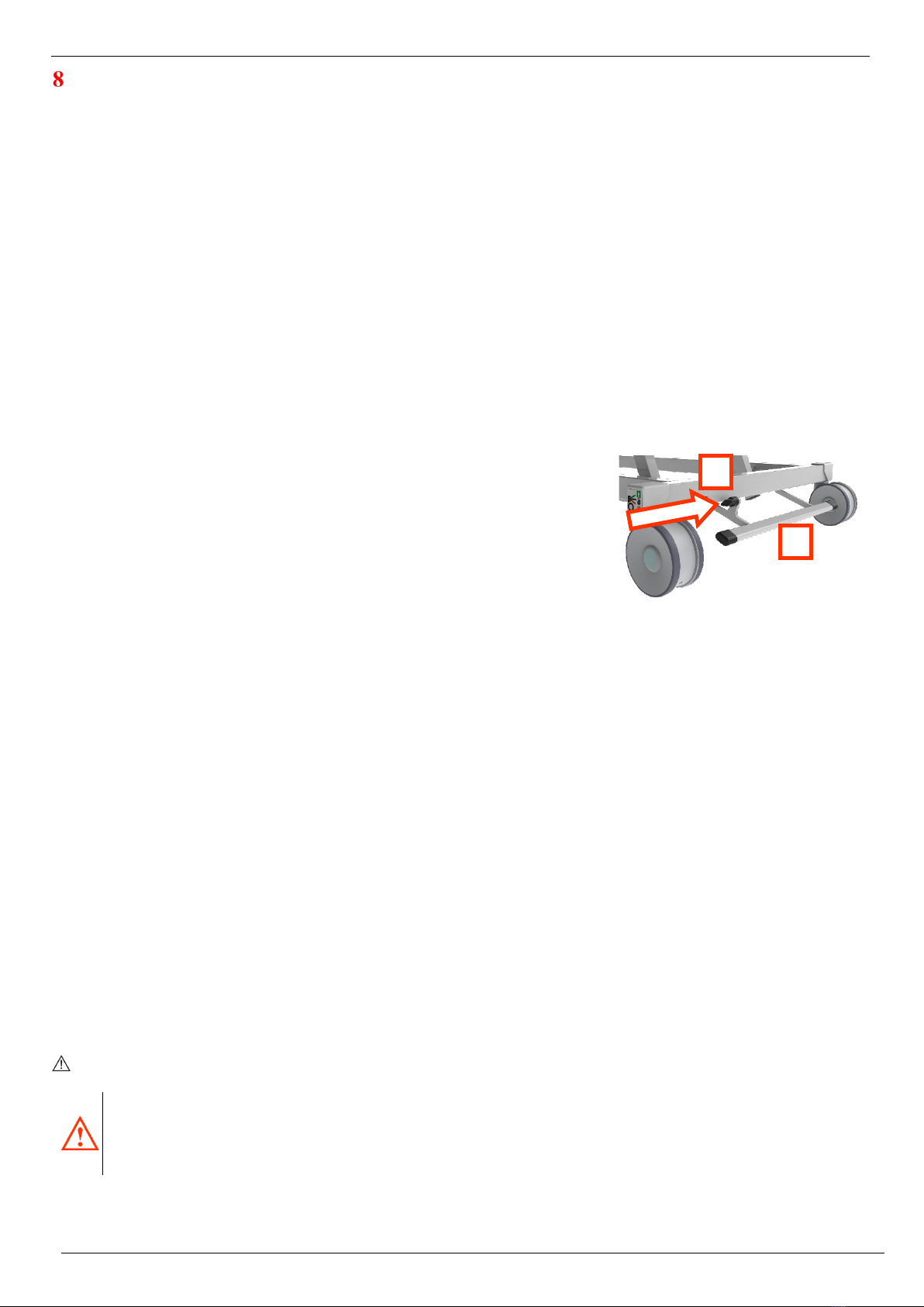
10.1 NURSE PANEL ONIMED
Before starting the first adjustment of position, you are obliged to fully familiarize yourself with the general operating
instructions of the electrical control elements in the chapter 10. The person not familiarized with the general operating
instructions must not control the beds!
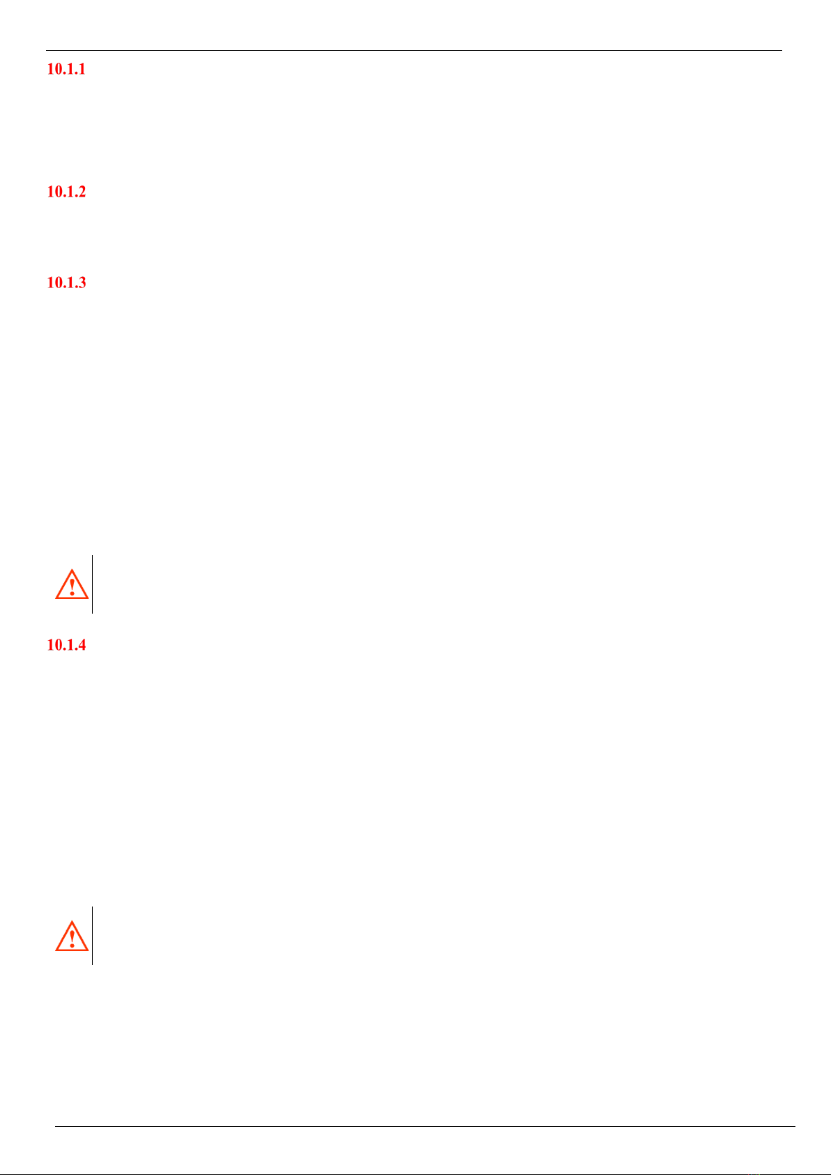
The bed can be equipped with the nurse panel. The panel is equipped with a hook at the back part for hanging the panel into the
headboard and footboard holes. You can find a description of the individual buttons and functions below:
1) Activation GO button
2) STOP button
3) Back part positioning
4) Thigh part positioning
5) “Auto contour” positioning
6) Bed height adjustment
7) Trendelenburg/Anti-
Trendelenburg
8) CPR
9) Getting out position
10) Examination position
11) Cardiac chair
12) Anti shock position
13) Function lock
14) Function lock indication
15) Display of the battery status
16) Indication of connecting to the
network
The bed is delivered in the OFF mode. After its switching on, insert the power supply cable into the electricity network. After inserting
the plug of the bed power supply cable into the 230V/50-60Hz network socket, the indication diode (16) signals the connection of
the nurse panel to the control unit and the bed to the network. If the bed does not go on itself, it is necessary to press the RESET
button located on the control box.
13
8
9
10
11
2
12
13
16
15
3
4
5
6
7
14
1
Instructions for Use of GENEO and GRANO Beds
Page 13/40
GO BUTTON
The nurse panel is protected against accidental activation. In order to use the control elements, it is always necessary to wake up the
nurse panel first by activating the GO button (1). An exception is the CPR emergency position, for which the activation of GO is not
necessary. After pressing the activation GO button, the LED diode is released and lit below the GO button. Subsequently, the nurse
panel is ready to accept the operator's requirements for 30 seconds. 30 seconds after the last push of the button, the controller goes
to the sleep mode again and must be activated again for the next control.
STOP BUTTON
The STOP button (2) is used for immediate finishing the positioning from any controller and measuring the 30-second time interval
to perform the necessary measures via the nurse panel. Other panels remain deactivated for this time period, even after pressing the
GO button (1). To reactivate the nurse panel press the activation GO button (1) first.
STANDARD ADJUSTMENT
Press the GO button (1) to activate the nurse panel, then the bed can be positioned. Always operate the given functions by pressing
and holding the relevant button until the required position is set. After releasing the button, the part will be automatically locked in
the position in which it is currently located. If the adjusted part reaches its maximum or minimum position, it is not possible to adjust
it further in the given direction. Then it is possible to position the given part only in the opposite direction. Adjust individual parts
by pressing the relevant button upwards or downwards:
•Back part (3)
•Thigh part (4)
•Auto contour (5) – simultaneous positioning of the back and thigh part
•Height of the bearing area (6) – (height adjustment of the bearing area)
•Trendelenburg (7 ↓) — head down, legs up
•Anti-Trendelenburg (7 ↑) — head up, legs down
Pay increased attention to adjusting the bed position because it can result in the patient falling out. Positioning to the special
Trendelenburg and Anti-Trendelenburg positions is only permitted for medical professionals.
ONE-BUTTON POSITIONS
For simpler and faster settings of the frequently used positions, the nurse panel is equipped with quick “one-button” functions. To
adjust the given positions activate the nurse panel by pressing the GO (1) button followed by pressing and holding the respective
button until the required position is set. In order to use the CPR function, it is not necessary to activate the nurse panel using the GO
button:
•CPR (8) – individual parts of the bearing area and the bearing area go to the lowest position suitable for
cardiopulmonary resuscitation
•Getting out position (9) – the back part moves to the maximum position and the bearing area runs to the lowest position
suitable for safe leaving the bed
•Examination position (10) – individual parts of the bearing area are tilted to the lowest position and the bearing area
is set to the highest position
•Cardiac chair (11) – the bed is set to the chair position
•Anti shock position (12) –individual parts of the bearing area are tilted to the lowest position and the bearing area is
tilted to the Trendelenburg position
The CPR and Trendelenburg functions or the anti shock position, must only be used by healthcare professionals and
used in emergency situations only. There may be an increased risk of the patient falling out of the bed!
During positioning to special positions, the patient must always be under the supervision of healthcare professionals!
Positioning to the special Trendelenburg and Anti--
Trendelenburg positions is only permitted for medical
professionals. There may be an increased risk of the patient falling out of the bed!
During positioning to special positions, the patient must always be under the supervision of healthcare professionals!
Instructions for Use of GENEO and GRANO Beds
Page 14/40
FUNCTION LOCK USING THE NURSE PANEL
The nurse panel is used to lock the individual functions of the patient controller in order to prevent them from being activated by the
patient. After locking the function on the patient controller, this function remains available for control from the nurse panel. Lock
the individual functions as follows:
•Activate the nurse panel using the GO button (1)
•Press one of the function lock buttons (13) simultaneously with one of the function buttons that you want to lock (3,
4, 5, 6 or 7) - e.g. function lock button (13) + one of the Back part positioning buttons (3) to lock the back part positioning
function
•Locked function is indicated by the LED diode (14) going on above the locked function and indicating the lock on
the patient controller
•Unlock the function by repeated pressing the Function lock button (13) and the required functions (3, 4, 5, 6 or 7)
The function locks to improve patient safety. Professional health staff decide on the patient’s ability to perform partial
positioning of the bed separately. Always carefully consider which functions can be safe and available for self-control
by the patient, taking into account their health and mental condition!
10.2 NURSE PANEL LINAK
Before starting the first adjustment of position, you are obliged to fully familiarize yourself with the general operating
instructions of the electrical control elements in the chapter 10. The person not familiarized with the general operating
instructions must not control the beds!
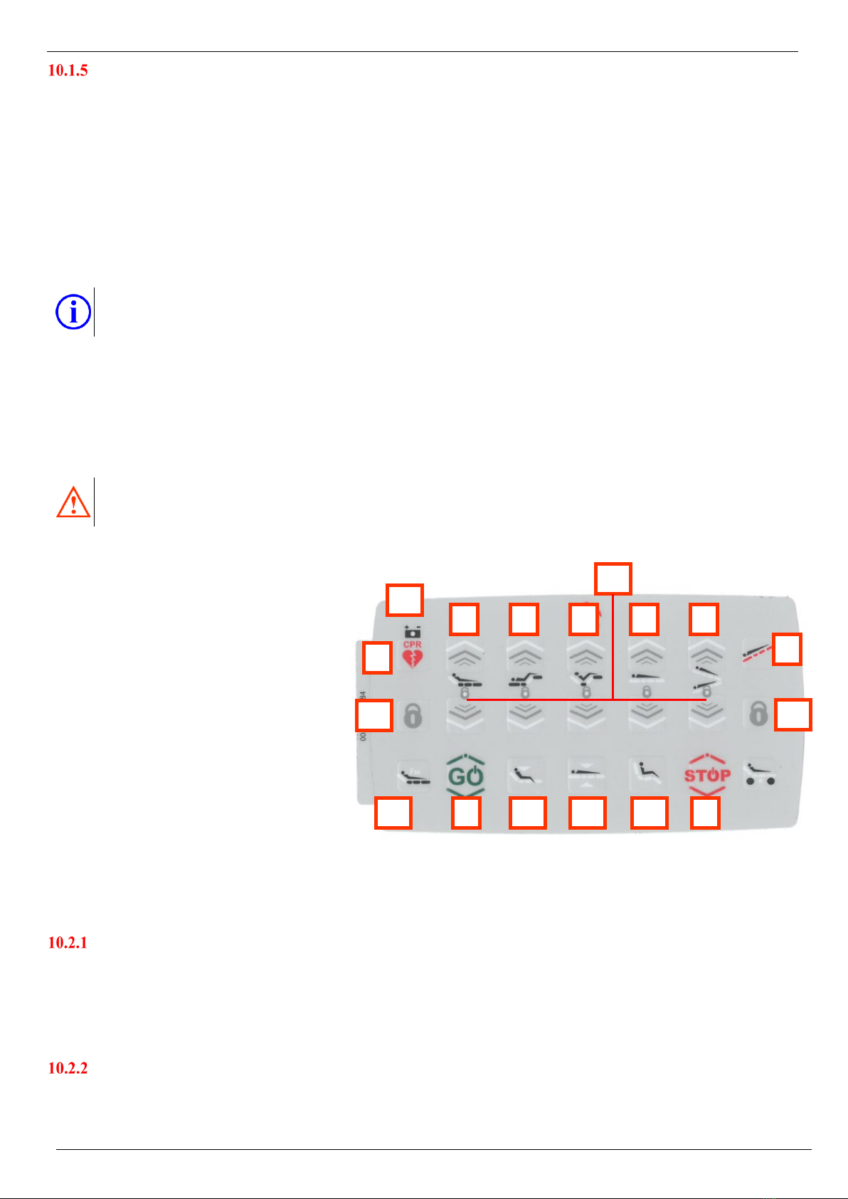
The bed can be equipped with the nurse panel. The panel is equipped with a hook at the back part for hanging the panel into the
headboard and footboard holes. You can find a description of the individual buttons and functions below:
1) Activation GO button
2) STOP button
3) Back part positioning
4) Thigh part positioning
5) “Auto contour” positioning
6) Bed height adjustment
7) Trendelenburg/Anti-
Trendelenburg
8) Anti shock position
9) CPR
10) Examination position
11) Cardiac chair
12) Getting out position
13) Function lock
14) Function lock indication
15) Display of the battery status
16) Fowler’s position
The bed is delivered in the OFF mode. After turning it ON insert the power supply cable plug into the 230 V/50-60 Hz power network
socket. The bed activation is signalled with a short beep.
GO BUTTON
The nurse panel is protected against accidental activation. In order to use the control elements, it is always necessary to wake up the
nurse panel first by activating the GO button (1). An exception is the CPR emergency position, for which the activation of GO is not
necessary. After pressing the activation GO button, the activation will take place. Subsequently, the nurse panel is ready to accept
the operator's requirements for 30 seconds. 30 seconds after the last push of the button, the controller goes to the sleep mode again
and must be activated again for the next control.
STOP BUTTON
The STOP button (2) is used for immediate finishing the positioning from any controller and measuring the 30-second time interval
to perform the necessary measures via the nurse panel. Other panels remain deactivated for this time period, even after pressing the
GO button (1). To reactivate the nurse panel press the activation GO button (1) first.
9
8
1
2
3
7
6
5
4
10
14
16
13
13
12
11
15
Instructions for Use of GENEO and GRANO Beds
Page 15/40
STANDARD ADJUSTMENT
Press the GO button (1) to activate the nurse panel, then the bed can be positioned. Always operate the given functions by pressing
and holding the relevant button until the required position is set. After releasing the button, the part will be automatically locked in
the position in which it is currently located. If the adjusted part reaches its maximum or minimum position, it is not possible to adjust
it further in the given direction. Then it is possible to position the given part only in the opposite direction. Position individual parts
by pressing the relevant button upwards or downwards:
•Back part (3)
•Thigh part (4)
•Auto contour (5) – simultaneous positioning of the back and thigh part
•Trendelenburg (6 ↓) — head down, legs up
•Anti-Trendelenburg (6 ↑) — head up, legs down
•Height of the bearing area (7) – height adjustment of the bearing area
Pay increased attention to adjusting the bed position because it can result in the patient falling out. Positioning to the special
Trendelenburg and Anti-Trendelenburg positions is only permitted for medical professionals.
ONE-BUTTON POSITIONS
For simpler and faster settings of the frequently used positions, the nurse panel is equipped with quick “one-button” functions. To
adjust the given positions activate the nurse panel by pressing the GO (1) button followed by pressing and holding the respective
button until the required position is set. In order to use the CPR function, it is not necessary to activate the nurse panel using the GO
button:
•Anti shock position (8) –individual parts of the bearing area are tilted to the lowest position and the bearing area is
tilted to the Trendelenburg position
•CPR (9) – individual parts of the bearing area and the bearing area go to the lowest position suitable for
cardiopulmonary resuscitation
•Examination position (10) – individual parts of the bearing area are tilted to the lowest position and the bearing area
is set to the optimum position for patient examination.
•Cardiac chair (11) – the bed is set to the chair position
•Getting out position (12) – the back part moves to the maximum position and the bearing area runs to the lowest
position suitable for safe leaving the bed
•Fowler’s position (16) – the back part is positioned up to 30° This position relieves the pain and facilitates breathing.
The CPR and Trendelenburg functions or the anti shock position must only be used by healthcare professionals and
used in emergency situations only. There may be an increased risk of the patient falling out of the bed!
During positioning to special positions, the patient must always be under the supervision of healthcare professionals!
FUNCTION LOCK USING THE NURSE PANEL
The nurse panel is used to lock the individual functions of the patient controller in order to prevent them from being activated by the
patient. After locking the function on the patient controller, this function remains available for control from the nurse panel. Lock
the individual functions as follows:
•Activate the nurse panel using the GO button (1)
•Press one of the function lock buttons (13) simultaneously with one of the function buttons that you want to lock (3,
4, 5, 6 or 7) - e.g. function lock button (13) + one of the Back part positioning buttons (3) to lock the back part positioning
function
•Locked function is indicated by the LED diode (14) going on above the locked function and indicating the lock on
the patient controller
•Unlock the function by repeated pressing the Function lock button (13) and the required functions (3, 4, 5, 6 or 7)
The function lock is used to improve patient safety. Professional health staff decide on the patient’s ability to perform
partial positioning of the bed separately. Always carefully consider which functions can be safe and available for self-
control by the patient, taking into account their health and mental condition!
Positioning to the special Trendelenburg and Anti--
Trendelenburg positions is only permitted for medical
professionals. There may be an increased risk of the patient falling out of the bed!
During positioning to special positions, the patient must always be under the supervision of healthcare professionals!

Instructions for Use of GENEO and GRANO Beds
Page 16/40
10.3 PATIENT HAND CONTROLLER WITH ILLUMINATION
Before starting the first positioning, you are obliged to fully familiarize yourself with the general operating
instructions of the electrical elements in the chapter 10.The person not familiarized with the general operating
instructions must not control the beds!
Beds are equipped with the patient hand controllers. If the bed is on, the lights on the controller
are slightly illuminated. Follow the steps below to use the hand controller. Press the GO button
(1) to activate the controller. The GO button goes on (1) and the illumination gets more intensive.
Then press and hold the button of the required function until the positioned part reaches the
required position. Then release the button, the part is automatically locked. If you reach the
maximum position, positioning is stopped and further positioning is possible only in the opposite
direction.
Position individual parts by pressing the relevant button upwards or
downwards:
(2) and (3) - back part positioning
(4) and (5) - thigh part positioning
(6) a (7) - Auto contour function (you adjust the back and thigh parts
simultaneously)
(8) and (9) - positioning of the bearing area
(10) * - Anti-Trendelenburg position (the bearing position is tilted with
the head up)
(11) * - Trendelenburg function (the bearing area is tilted with the head
down) only if the bed is provided with the battery source
(14) - Cardiac chair (can replace the TR / ATR functions)
The controller is also equipped with the FN (12) button as an additional
function at the customer's request and is used for lighting for a patient (13).
Pay increased attention to the adjustment of the bed position; in some
positions, there may be an increased risk of the patient falling out of the bed.
FUNCTION LOCK OF THE PATIENT CONTROLLER
Individual functions of the patient controller can be locked. Locked function is indicated by
changing the illumination from white to red for the given function.
Lock the individual functions using the magnetic wrench as follows:
•Activate the controller using the GO button (1)
•Attach the magnetic key to the lock (see figure); the
buttons on the controller start flashing (lock mode
indication)
•Press the button of the function you want to lock.
•For the given function, the illumination changes from
white to red
•Terminate the lock mode by pressing the GO button (1);
the buttons on the controller will stop flashing
UNLOCK the function by repeating the above procedure. After pushing the locked function,
the function lock indication will go out (10).
After the universal plastic key has been inserted into the controller, the buttons on
the patient controller will start flashing!
The function locks to improve patient safety. Professional health staff decide on
the patient’s ability to perform partial positioning of the bed separately. Always
carefully consider which functions can be safe and available for self-control by the
patient, taking into account their health and mental condition!
One universal key can be used to lock all beds of the same type!
1
1
2
3
6
4
5
7
12
9
8
11
10
14
13

Instructions for Use of GENEO and GRANO Beds
Page 17/40
TRENDELENBURG/ANTI-TRENDELENBURG
The bed may be equipped with the function of adjusting the bearing area to the Trendelenburg position (patient’s head down) and
the Anti-Trendelenburg position (patient’s head up). To use the function, press the button (10) or (11), if your controller contains it.
To level the bed to the horizontal plane, adjust it to the maximum or minimum height.
When adjusting the bearing area to the Trendelenburg / Anti-Trendelenburg positions, no foreign object may
interfere with the working space, i.e. under the bearing surface or above the bearing surface. It could result in
damage or bodily harm!
Only professional personnel is authorized and can use the Trendelenburg and Anti-Trendelenburg positions.
However, they should always be used only in such a way that the patient's health is not compromised!

Instructions for Use of GENEO and GRANO Beds
Page 18/40
CONTROLLERS INTEGRATED IN SIDERAILS
The bed may be equipped with integrated hand controllers glued on the outside and inside of both siderails along the back part of the
bearing area.
•Press the GO button (1) to activate the controller - LED indication goes on (15) for 15 seconds. 15 seconds after the last
use of the controller, it deactivates itself! If the nurse panel is activated, it is not possible to activate the controller. Activate
the controller only after the nurse panel goes out.
•Adjust individual parts by pressing the relevant button upwards or downwards:
2) Back part
3) Thigh part
4) Calf part
5) Trendelenburg / Anti-Trendelenburg
6) Auto contour – back and thigh parts at the same time
7) Bearing area height
8) Cardiac chair
9) Fowler’s position
10) Examination position
11) Position of leaving the bed easily
12) Patient lamp – inner side of the siderail (optional extra)
13) CPR – on the outside of the siderail
14) Chassis illumination (optional modification)
15) Bearing area UPWARDS – patient mobilisation function
16) Bearing area DOWNWARDS – patient mobilisation function
Pay increased attention to the adjustment of the bed position; in some positions, there may be an increased risk of the patient
falling out of the bed.
If any of the buttons do not work correctly and do not adjust individual parts of the bed as required by the operator,
always check first whether the controller was activated using the activation GO button, or whether the required
function is not blocked by a lock on the nurse panel. Locked function is indicated by the function lock LED on.
The part you want to position can also be in the limit position where it can only be adjusted in the opposite direction.
If none of the above options is helpful, continue with the chapter PROBLEMS AND THEIR
TROUBLESHOOTING
Positioning to the special Trendelenburg and Anti-Trendelenburg positions is only permitted for trained medical
staff. There may be an increased risk of the patient falling out of the bed!
When positioning to special positions, the patient must always be under the supervision of healthcare professionals!
1
2
3
4
5
6
7
8
9
10
11
16
15
12
13
14
12
15
16
Instructions for Use of GENEO and GRANO Beds
Page 19/40
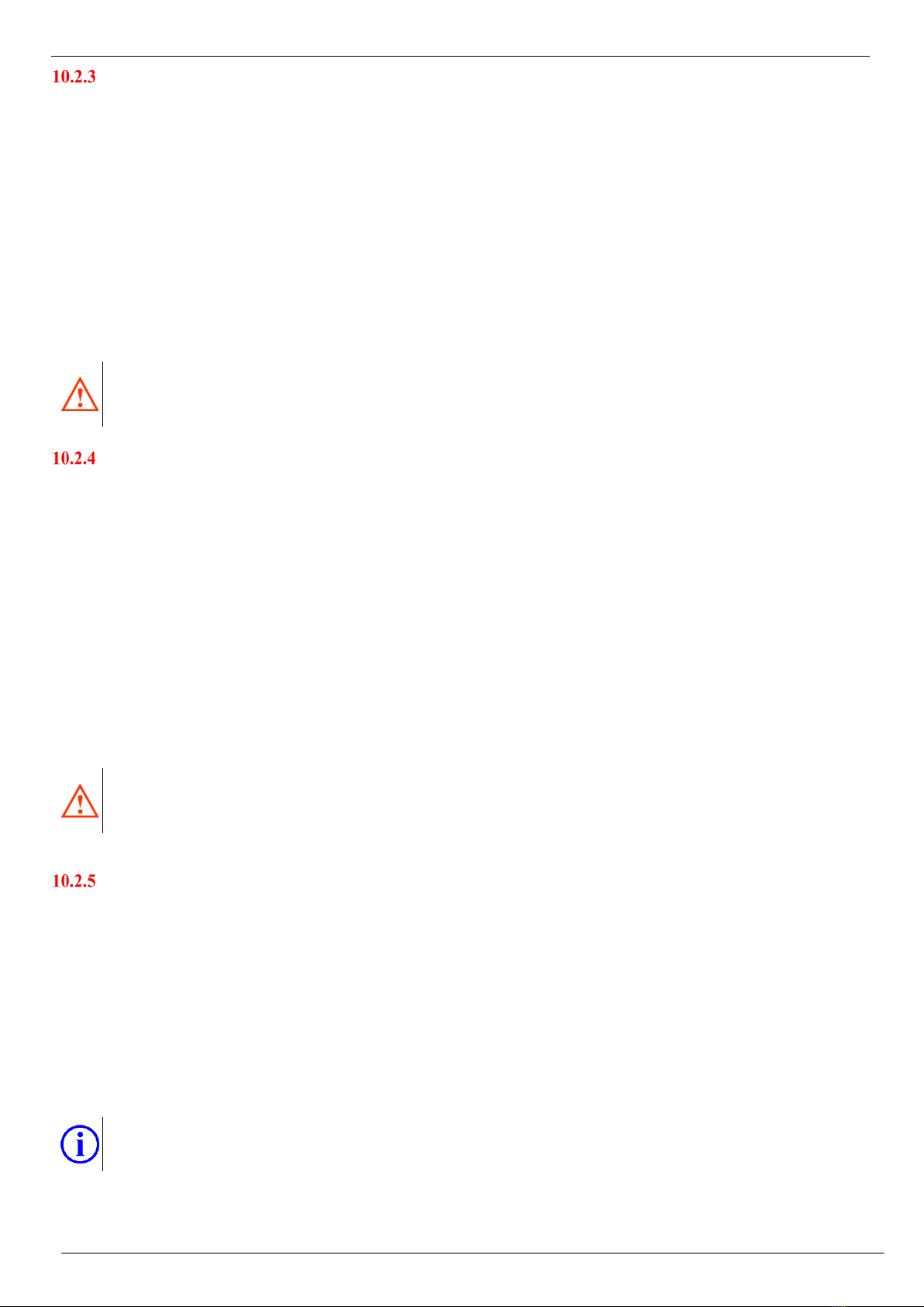
10.5 FUNCTION OF PATIENT MOBILISATION
The bed may be equipped with a patient’s mobilisation function located on the head siderail in combination with the mobilisation
handle on the foot siderail. Observe the following procedure to use the patient’ s mobilisation function.
•Press the GO button (1) to activate the controller
•Press and hold the button of Position of (8) leaving the bed easily on the
controller; this can be controlled by both the patient and the nurse. The bed is
lowered to the lowest position and the back part is lifted.
•Lower the foot siderail
•Turn the patient on the bearing area and lower his/her feet on the floor
•Pull out the mobilisation handle and turn it up to secure it
•The patient holds on to one side of the mobilisation handle in the head and foot siderail
•Press the GO button (1) to activate the small controller
•The patient or nurse will press the upward mobilisation button (A) – the bed is moving up and helps the patient get
out of the bed
•The patient or nurse will press the down mobilisation button (16) – the bearing area goes down and helps the patient
sit back on the bed
It is forbidden to use the mobilisation function without the supervision of health care personnel! When getting up and
taking a seat on the bed, there may be an increased risk of falling due to the state of the patient's health!
Brake the wheel before using the mobilisation function!
The use of the patient’ s mobilisation function is decided by healthcare professionals on the basis of the patient’s
health and mental status. During the use of the function, the personnel are always fully responsible for the state of the
patient's health!
15
16

Instructions for Use of GENEO and GRANO Beds
Page 20/40
10.6 SATELLITE PATIENT CONTROLLER
Before starting the first positioning, you are obliged to fully familiarize yourself with the general operating
instructions of the electrical control elements in Chapter 10.1. The person not familiarized with the general operating
instructions must not control the beds!
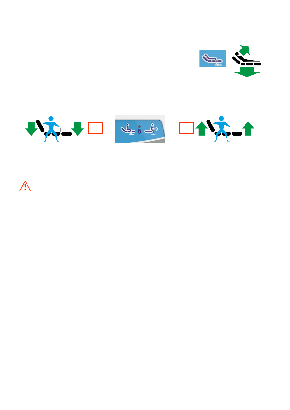
The bed may be equipped with a patient satellite controller.
If the bed is on, the information LED (2) lights on the
controller is green. Carry out the following steps for using
the controller:
•Press the GO (1) button to activate the
controller – the illumination of the controller is
activated for 15 seconds. 15 seconds after the last
use of the controller, it deactivates itself! If the
nurse panel is activated, it is not possible to activate
the controller. Activate the controller only after the
nurse panel goes out.
•Adjust individual parts by pressing the relevant
button upwards or downwards:
3) Back part
4) Thigh part
5) Cardiac chair
6) Bearing area height (reduced position of the bearing area, see chapter 10.6)
7) Lamp – switches on / off the light on the back of the satellite controller
8) Function lock – if the red LED of the lock is on, the function is locked using the sister panel
Pay increased attention to adjusting the bed position because it can result in the patient falling out.
10.7 CHASSIS ILLUMINATION
The bed may be equipped with a chassis illuminating function. This function is used to improve the orientation of the patient while
getting out of the bed under worsened light conditions, e.g. at night, where there may be an increased risk of the patient falling due
to poor orientation (tripping, slipping, etc.). If the bed is equipped with a chassis illuminating function, the function is automatically
activated each time the bed is positioned to the lowest height suitable for seating on and getting out of the bed. Carry out the following
steps for using the chassis illumination:
AUTOMATIC LIGHT ON/ OFF
•Use the nurse panel or the patient controller and adjust the bed to the
lowest position – the LED diode in the bed chassis will automatically go on
•Use the nurse panel or the patient controller and move the bed up from
the lowest position – the LED diode in the bed chassis will turn off
automatically
MANUAL LIGHT ON / OFF
•Use the hand patient controller for manual activation / deactivation
•Press at length (more than 2 seconds) the FN button on the controller – the LED diode in the bed chassis goes on / out
independently of the height position of the bed
If any of the buttons do not work correctly and do not adjust individual parts of the bed as required by the operator,
always check first whether the controller was activated using the activation GO button, or whether the required
function is not blocked by a lock on the nurse panel. Locked function is indicated by the function lock LED on (10).
The part you want to position can also be in the limit position where it can only be adjusted in the opposite direction.
If none of the above options is helpful, continue with the chapter PROBLEMS AND THEIR
TROUBLESHOOTING.
When positioning to special positions, the patient must always be under the supervision of healthcare
professionals!
The chassis illumination automatically starts in the lowest height position of the bed - optimum position for getting
out of / seating on the bed. Adjust the bed to the lowest height, if the patient remains unsupervised by health care
personnel!
1
2
3
4
5
6
7
8
This manual suits for next models
1
Table of contents
Other PROMA REHA Medical Equipment manuals


