TRI-FLEX BED - OPERATION MANUAL 9
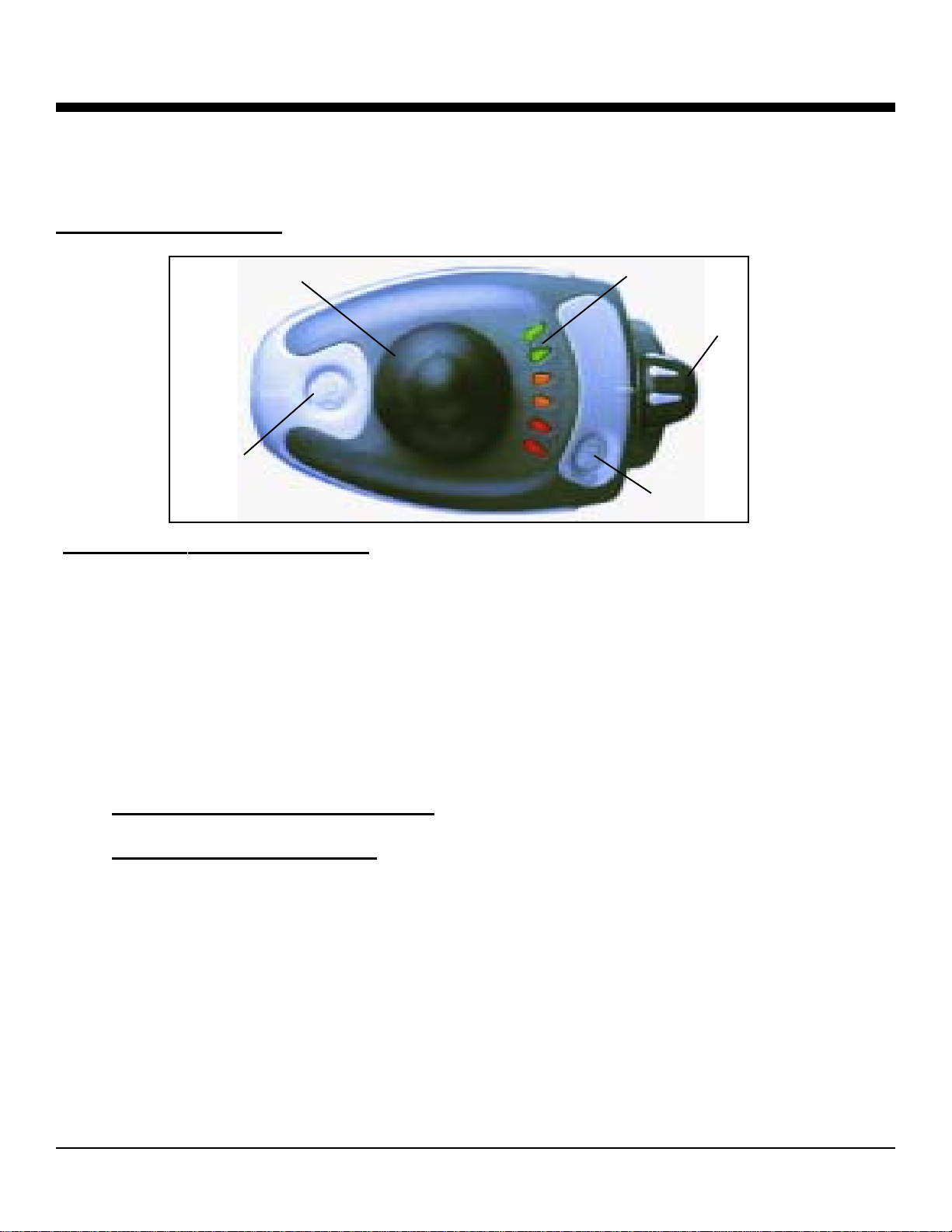
Major Component Identification
CHARGINGTHEDRIVESYSTEMBATTERIES
Charging the batteries is the most important part of operating and maintaining the drive
system. Be sure you do it properly! It is required that only a gel cell or sealed suspended lead-acid
type deep cycle battery be used on the drive system. These batteries do not require water and have
no danger of spillage.
Introduction to Features of the Charger
The charger is fully automatic and has a 24-volt/ 2 -ampere constant current output. It is designed
to operate from a 115vAC line source and provides a constant charging output until the batteries
are fully charged.
The charger is recommended for use with deep cycle, gel or sealed lead acid batteries, and can be
left "on charge" indefinitely without harm to the batteries.
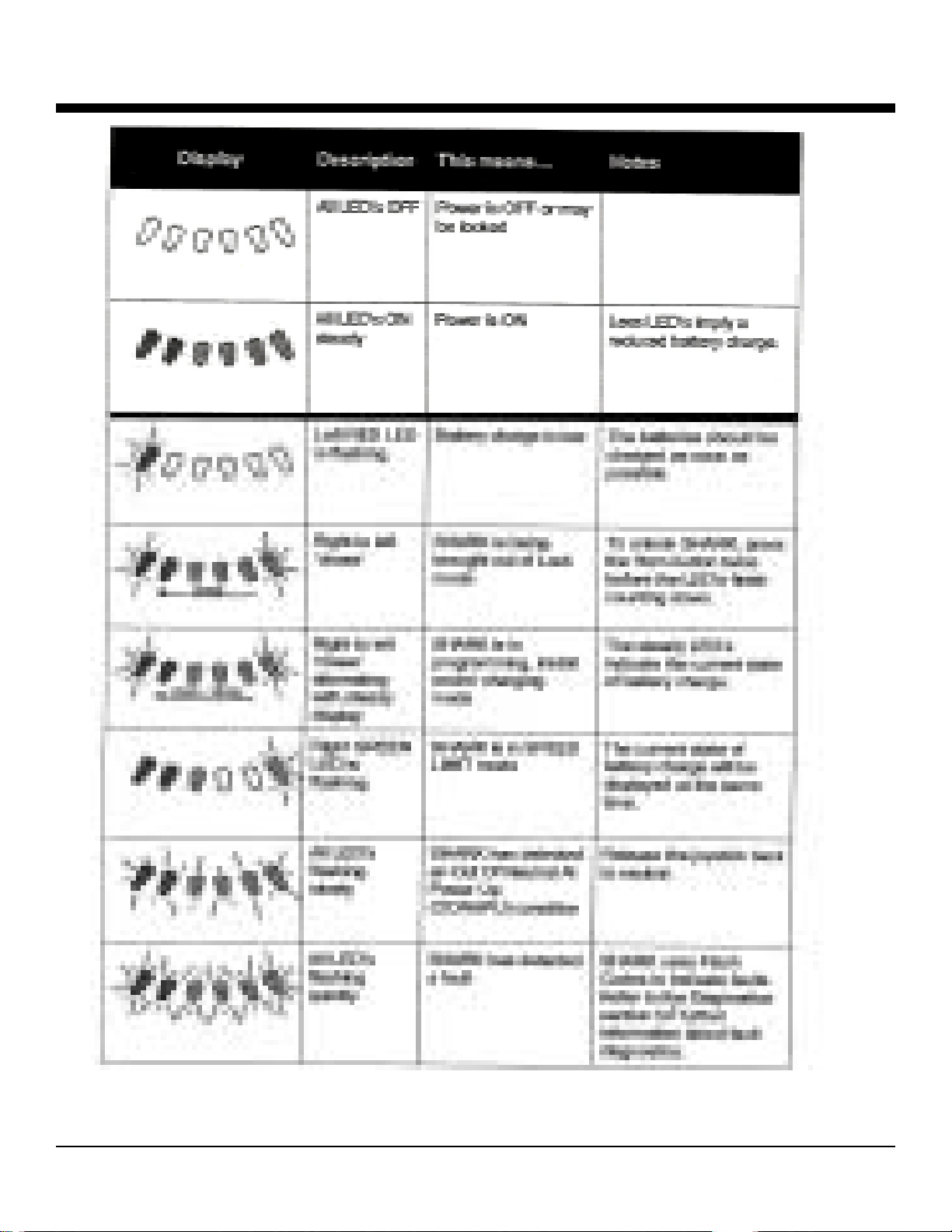
This charger is provided with a Light Emitting Diode (LED) on the front that provides the follow-
ingindications:
1. When the AC is connected to the charger and the charger is connected to the batteries the
greenLED willflash.
2. At full battery charge -the green LED turns to steady on, and the charger goes to a
float mode (charges at a lower rate than the 2-amperes) and continues to monitor the
batteries.
Basic Safety Instructions:
1. Do not expose the charger to rain, snow or other moisture sources (i.e., sprinkler, car wash, etc.).
When storing bed, keep inside a building.
2. Use of the charger in a manner not recommended by the manufacturer may result in the risk of fire,
electrical shock or personal injury.
3. To reduce the possibility of damage to the AC cord or the connector, disconnect the AC line cord by
grasping the plug and not the cord, when disconnecting from the wall or receptacle.
4. Locate cord so that it will not be stepped on, tripped over or subjected to the possibility of damage.
5. An extension cord is not recommended for use with this equipment. Use of an improperly
rated extension cord could result in risk of fire or electrical shock. Should it be required to use an
extension cord, make certain that it is of 3-wire construction and has a wire size of 16-gauge, and
the cord must be in good electrical condition.
6. Do not operate this charger with damagedAC cord or receptacle. If they are damaged, replace
them immediately.