Promeba PB-440 User manual

USER GUIDE
ELEVATOR // PB-440
Review 01/19


USER MANUAL // ELEVATOR PB-440
Review 01/19
3
INDEX
01 INTRODUCCIÓN
01.1 Using this manual 05
01.2 Technical data sheet 06
02 INSTALATION
02.1 Transporting and unpacking 07
02.2 Anchorage points 08
02.3 Connection to the electric grid 09
03 OPERATING
03.1 Commands 11
03.2 Elements of the manual system 12
03.3 Loading and unloading operation 12
03.4 Electric motion within the ambulance 15
04 MOUNTING AND COMPONENTS
04.1 Main exploded view 17
04.2 Explosionado plataforma superior PB-440/5 18
04.3 Listado de referencias plataforma superior PB-440/5 23
04.4 Explosionado plataforma superior PB-440/2 26
04.5 Listado de referencias plataforma superior PB-440/2 31
04.6 Conjunto plataforma base PB-440/5 · PB-440/2 34
04.7 Listado de referencias conjunto plataforma base PB-440/5 · PB-440/2 35
04.8 Explosionado carro elevador PB-440/5 · PB-440/2 36
04.9 Listado de referencias carro elevador PB-440/5 · PB-440/2 37
04.10 Conjunto guia elevador PB-440/5 · PB-440/2 38
04.11 Listado de referencias guia elevador PB-440/5 · PB-440/2 39
04.12 Explosionado guia elevador PB-440/5 · PB-440/2 40
04.13 Listado de referencias guia elevador PB-440/5 · PB-440/2 41
05 ELECTRICAL CIRCUIT DIAGRAM
05.1 Printed circuit board 43
05.2 PIN conector Hand control 44
06 GENERAL MAINTENANCE 46
07 LEGAL NOTICES 47
08 PRODUCT WARRANTY 48
MODEL PB-440/5
WITH LONGITUDINAL
SLIDING PLATFORM
MODEL PB-440/2
WITH LONGITUDINAL
SLIDING PLATFORM


USER MANUAL // ELEVATOR PB-440
Review 01/19
5
01.1 Using this manual
This manual provides using and maintenance instruc-
tions of the product, as well as the way of xing minor
faults that could appear.
It is recommended before the operation of the product
to read carefully this manual in order to avoid damages
caused by a misuse.
Do not lose this document, it should be accessible to
any doubt that could appear by medical personnel.
Remember that a good use and maintenance are ne-
cessary for the proper operation of the product.
Each product incorporates an identication sticker with
the serial number and the model. Keep these numbers
so that they can be indicated to the dealer if necessary.
01 INTRODUTION

USER MANUAL // ELEVATOR PB-440
Review 01/19
6
01.2 Technical data sheet
MEASURES AND FEATURES // PB-440/2 + PB-440/5 WITH SIDE MOVEMENT
LENGHT 2018 mm/ 2218 mm ELECTRIC SUPPLY 12 V. CC.
WIDTH 630 mm POWER CONSUMPTION 100A
HEIGHT 425 mm TRENDELEMBURG -15º / +10º
WEIGHT 112-127 Kg HEIGHT LOADING ± 315 mm
MAX. LOAD 250 Kg SIDE MOVEMENT 300 mm
01 INTRODUCTION
630
425
2018 mm/ 2218 mm

USER MANUAL // ELEVATOR PB-440
Review 01/19
7
02.1 Transport and unpacking
First carefully remove the packaging to prevent the da-
mage of the outside of the stretcher support.
1. Transport with a crane (high load)
· Thread tapes through the upper platform for its trans-
port (as shown in graphs)
· Transport the load level following all the precepts and
regulations for the transport of suspended loads.
2. Transport with a forklift
· Place a pallet or a at surface under the bench and
transport it transversely.
· Do not load the bench directly on the forklift without
a pallet or a at support surface.
· Do not load the bench longitudinally on the forklift if
a suciently long base is not available.
· Every bench has been thoroughly inspected leaving
the factory. To ensure that it hasn’t been damaged du-
ring the transport, it is requested to carefully examine
the interior and exterior, and in case of nding any da-
mage, communicate immediately to the installer.
· The bench should be levelled for an optimum perfor-
mance.
02 INSTALATION
TRANSPORT WITH A CRANE
FIX THE TAPES TO LEVEL THE LOAD WEIGHT
TRANSPORT WITH A FORKLIFT
USE ALWAYS A FLAT SUPPORT SURFACE
USER MANUAL // ELEVATOR PB-440
Review 01/19
8
02 INSTALATION
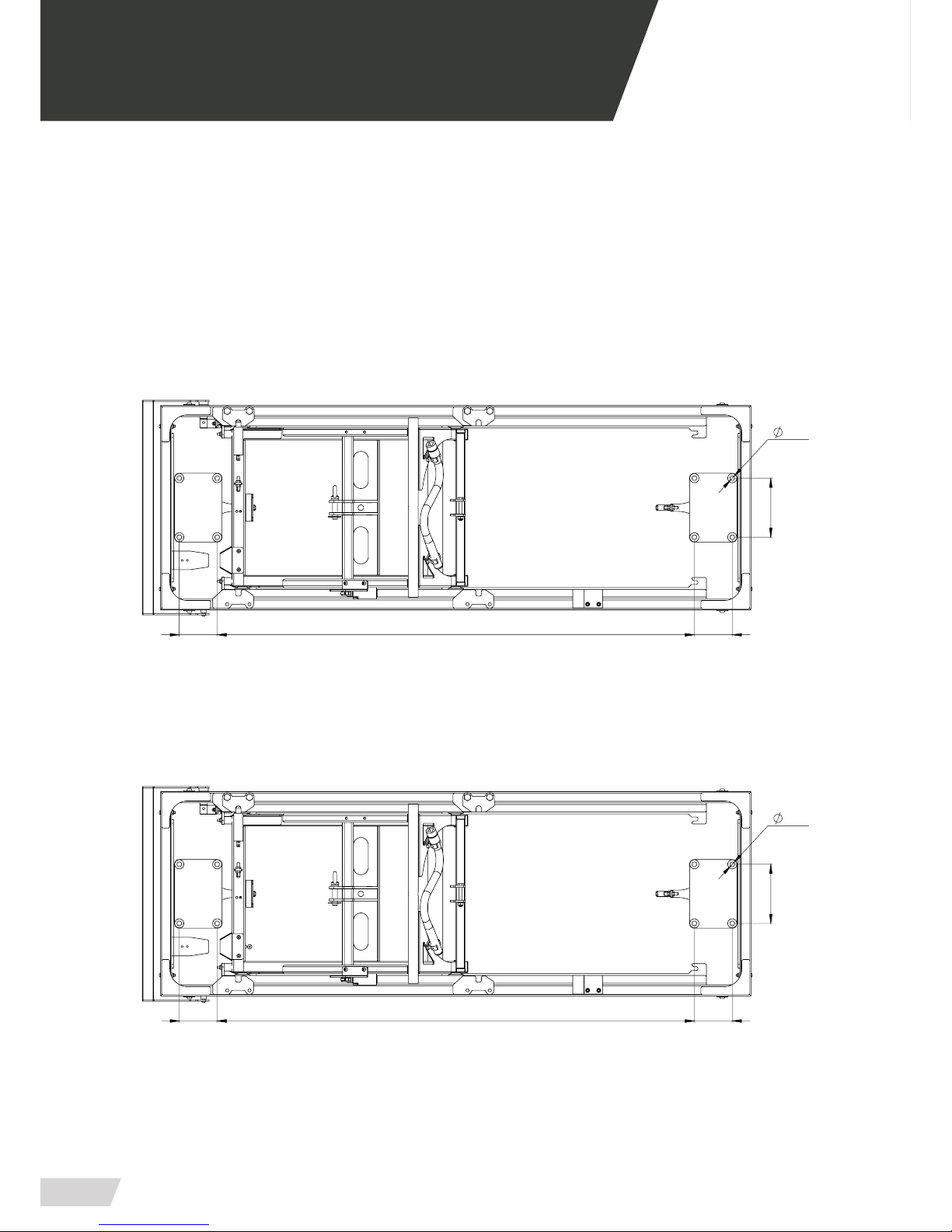
02.2 Anchore points
Before putting the bench into operation, ensure that
each and every anchorage points are placed and
clasped.
ANCHORE FOR PB-440/5
(8 anchorage points)
ANCHORE FOR PB-440/2
(8 anchorage points)
Power chord
12V. CC.
102 1285 102
12,5
159
102 1285 102
159
12,5

USER MANUAL // ELEVATOR PB-440
Review 01/19
9
02 INSTALATION
02.3 Connection to the mains power supply
To make the connection follow the steps below.
Be particularly careful when connecting the bench to the required voltage of 12V direct current and
do not leave cables in passageways and or moving elements.
B
Remove the plastic end of the red and
black cables with a thread peeler to
make the connection.
C
Use a power strip and a athead
screwdriver to connect the red and
black cables with the outlet of the
ambulance.
To make the connection locate the black cable located at the front side of the
bench.
MAKE SURE YOU HAVE THE POWER LINE PROPERLY PROTECTED AND ENSURE THAT THE
POWER ALONG THE LINE IS STABLE.
A
Power chord
12V. CC.

Table of contents
Popular Elevator manuals by other brands


Skandia Elevator
Skandia Elevator SEH 50/18 Assembly instructions

Cibes Lift
Cibes Lift A4000 Operating and maintenance instructions

Waupaca
Waupaca Paca-Ryde installation instructions

ThyssenKrupp
ThyssenKrupp SC300 operating manual

ZIEHL-ABEGG
ZIEHL-ABEGG ZAS0 Amendment of the original operating instructions

Cambridge Elevating
Cambridge Elevating BES 3 Service guide