pronovost PGS-1020TRC Programming manual

OPERATOR'S / PARTS
MANUAL
Snowblowers
Model
PGS-1020TRC
No. C2806 12/2011

Copyright © Les Machineries Pronovost Inc., 2011
All rights reserved.
Printed in Canada.

- 3 -
TABLE OF CONTENTS
Section Item Page
1 Introduction ................................................................................................................ 5
2 Safety .......................................................................................................................... 6
General Safety .................................................................................................. 6
Safety in Operation ........................................................................................... 6
Safety with Maintenance .................................................................................. 7
Safety in Transport ........................................................................................... 7
Safety in Storage ............................................................................................... 7
3 Decals .......................................................................................................................... 8
Safety Decals .................................................................................................... 8
Maintenance Decals ........................................................................................ 12
4 Assembly .................................................................................................................... 13
General assembly ............................................................................................ 13
Motor on the rotary drum ............................................................................... 14
Hydraulic Chute Kit: Motor............................................................................ 15
5 Start-up ...................................................................................................................... 16
Basic Start-up Procedures ............................................................................... 16
6 Maintenance .............................................................................................................. 17
General maintenance .................................................................................................. 17
7 Storage ....................................................................................................................... 18
8 Trouble Shooting ...................................................................................................... 19
9 Specifications............................................................................................................. 20
10 Parts List ................................................................................................................... 22
Snowblower PGS-1020TRC .......................................................................... 22
Semi-industrial Chute PSIG-92104 ................................................................ 25
Industrial Chute PCG-92104 .......................................................................... 27
Hydraulic telescopic chute PCT-92104 ......................................................... 29
Hydraulic telescopic chute PCTC-INDR ....................................................... 31
Options ........................................................................................................... 34
P.T.O. Shaft T90 # 9475 ................................................................................. 37
P.T.O. Shaft V90 # 9598, 9599 & 9604 ......................................................... 38
Gear Box # 9307 ............................................................................................. 39
Reduction Gear Box PRH-25M-2 .................................................................. 40
Reduction Gear Box PRH-30M-2 .................................................................. 41
Reduction Gear Box PR3G200-2 # 9721 200 HP ......................................... 42
Cylinder 25TR08 ............................................................................................ 43
Cylinder 15PC32 ............................................................................................ 44
Cylinder 15PL12 ............................................................................................. 45
Hydraulic Motor MLH-315 ............................................................................ 46
11 Torque Chart ............................................................................................................ 47
12 Warranty ................................................................................................................... 48


- 5 -
MODEL:
SERIAL NO:
DATE OF PURCHASE:
INTRODUCTION 1
NOW take a moment to enter the model, serial
number and the date of purchase of your Snowblower
in the space provided.
When ordering parts from your Dealer, please refer to
these numbers for a fast and efficient service. Use
PRONOVOST parts for replacement.
The model and serial numbers are on the name plate
shown on Fig. 1b.
Thank you for choosing PRONOVOST. We are
confident this equipment will meet your requirements
in terms of quality, performance and reliability.
This manual was prepared to assist you in the safe
operation of your new Snowblower. It contains
important information which will help you achieve
excellent returns with your Snowblower for years to
come.
Please read this manual completely before operating
your Snowblower and keep it for future reference.
Before starting the machine, you or any other person
who will be operating the Snowblower must
familiarize yourself with the safety recommendations
and the operating instructions. Please read carefully
and be sure to understand and follow all
recommendations and procedures.
In this manual, the right and left sides are identified as
shown on Figure 1a.
If you require additional information on your
Snowblower, please contact your PRONOVOST
Dealer.
CONGRATULATIONS!
Right
Left
Figure 1a
Figure 1b

- 6 -
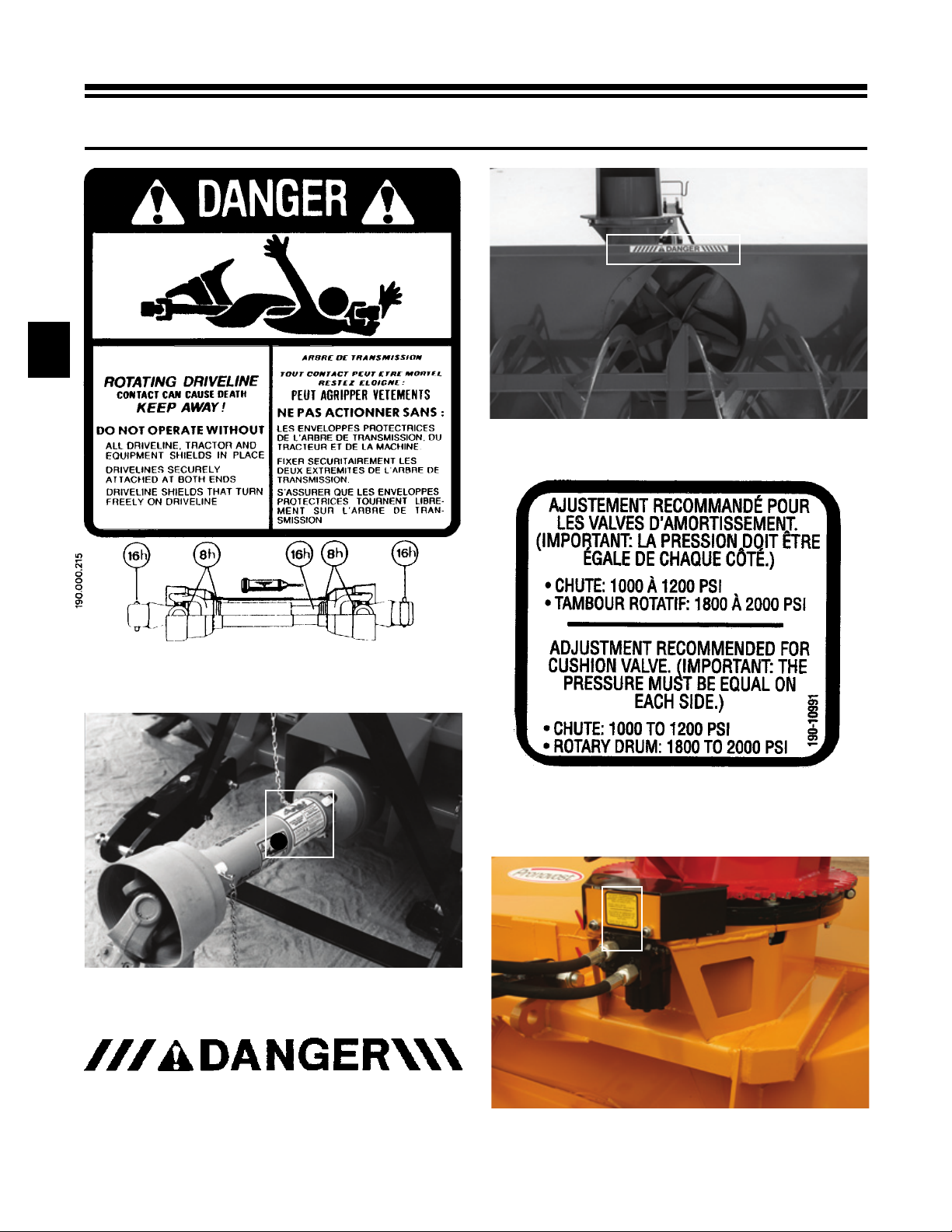
WHEN YOU SEE THIS SYMBOL
SAFETY
2
ATTENTION!
BE ALERT
YOUR SAFETY IS INVOLVED
This symbol «SAFETY ALERT» is used in this manual and
on the safety decals on the Snowblower. It warns you of the
possibility of danger. Carefully read, understand and follow
all safety recommendations before operating the
Snowblower.
1) Careful operation is the best assurance against acci-
dents. Carefully read this manual and follow all
recommendations before operating your Snowblower.
It is the owner’s responsibility to make sure that anyone
who will operate the Snowblower will read this manual
before operating the equipment.
2) Familiarize yourself with all controls and always be
ready to stop the Snowblower quickly in case of
emergency.
3) Never let a child operate the Snowblower.
4) Do not modify the Snowblower. Any non authorized
modification may affect the efficiency and/or safety of
the equipment and will automatically void the warranty.
5) Never operate the Snowblower with defective parts or if
damaged in any way. Have it repaired before operating.
6) Make sure all fasteners are in place and properly
secured or tightened. Refer to torque chart on page 47.
7) Avoid wearing loose fitting clothing when working with
the Snowblower. These could get entangled in moving
parts of the equipment and cause accidents.
GENERAL SAFETY
8) Prolonged exposure to noise may hamper hearing.
Protect yourself by wearing adequate protection
devices.
9) Hydraulic fluids under pressure can damage your skin.
Do not use your hands to locate a leak.
10) Before the beginning of the snow season, inspect all
areas where the Snowblower will be used and remove
any object which may cause an accident and/or damage
the equipment.
11) Never operate your Snowblower in poor visibility or
without proper lighting conditions.
SAFETY IN OPERATION
1) Be sure there are no obstructions around the equipment
and that no one stands near the equipment when in
operation.
2) Do not operate an engine in a confined or non ventilated
area.
3) Do not perform any adjustments, cleaning, maintenance
or repairs with the engine running. The engine must be
stopped and the P.T.O. disengaged. Preferably remove
the key from the ignition.
4) Wear adequate clothing when working in cold or windy
conditions.
5) Adjust skid shoes for proper ground clearance of
scraper blade, especially in rough terrain or soft ground
conditions.
6) Before operating, make sure the P.T.O. is properly
installed and secured.
7) Before starting-up the Snowblower, make sure the auger
and drum areas are free of ice.
8) Put P.T.O. control in neutral position before starting
engine.
9) Keep hands, feet and clothing away from moving parts
of the Snowblower. Stay away from the discharge chute.

- 7 -
SAFETY (cont'd)
2
10) Before unplugging the chute, always disengage the
P.T.O., stop the engine and relieve all hydraulic pressu-
res.
11) Do not operate in excessive inclined conditions. Be
careful when turning in slopes.
12) Never operate your Snowblower with missing guards or
without protective devices in place.
13) Do not operate your Snowblower near buildings,
windows or other vehicules without prior and proper
adjustment of the chute deflector.
14) Never aim discharge chute towards people or animals.
This may cause serious injuries.
15) Always reduce operating speed in slippery conditions.
16) Be careful when backing-up, make sure you have good
visibility.
17) Always be on the lookout for objects which may enter
the snowblower.
18) If undue vibrations are felt, disengage the P.T.O., stop
the motor and look for the cause of the vibration.
Vibration is usually the indication of a problem.
19) At the end of the operation, disengage the P.T.O., lower
the Snowblower, put transmission in neutral, apply
parking brake, stop engine and remove the key from the
ignition.
SAFETY WITH MAINTENANCE
1) Perform the Snowblower maintenance according to
recommendations contained in this manual.
2) Stop engine and relieve all hydraulic pressures before
doing inspection, maintenance or repairs.
3) Never perform any work under the Snowblower while it
is supported only by the tractor's hydraulic system. It
must be completely supported by wooden blocks or
other safe means.
SAFETY IN TRANSPORT
1) On public roads, use proper safety lights and check
local regulations.
2) Be alert while driving on the road. Never carry
passengers.
3) Always disengage P.T.O. while moving from one area
of work to another.
4) It is recommended to use both brake pedals
simultaneously for better control.
5) The recommended road speed should be such as to
maintain full control over steering and braking.
6) Be careful while backing up, make sure you have good
visibility.
SAFETY IN STORAGE
1) Provide adequate supports to prevent any accidental
overturning of the Snowblower.
2) Do not let children play in the area where the
Snowblower is stored.

- 8 -
DECALS
SAFETY DECALS
The safety decals are affixed wherever special safety
precautions are indicated. Locate them on the machine
and read them carefully. If a decal is damaged, lost or
illegible, install a new one. The following photos
indicate where each one must be installed.
3
Figure 2
Decal A Part no.: 190-11671
Figure 4
Decal B Part no.: 190-07722
Figure 3
Figure 5
A
BB

- 9 -
DECALS (cont'd)
3
Decal E in Fig. 9 is located directly on the P.T.O.
shaft. It is not visible when the safety shield is in
place. It must never be visible when you operate the
equipment. Figure 9
Decal E Part no.: A108
Figure 7
Decal C Part no.: 190-11641
If your snowblower is equipped with a reduction gear
box, the decal C will be the one shown below.
Figure 8
Decal C Pièce no.: 190-11651
Figure 6
C

- 10 -
DECALS (cont'd)
3
Figure 10
Decal F Part no.: A 109
Figure 11
F
Figure 15
Figure 14
Decal G Part no.: 190-10991
Figure 12
Decal D Part no.: A103
D
Figure 13
G

- 11 -
Figure 16
Decal H Part no.: 190-06651
DECALS (cont'd)
3
Figure 18
Decal J Part no.: 190-07611
Figure 17
H
Figure 19
J

- 12 -
DECALS (cont'd)
3
MAINTENANCE DECALS
The maintenance decals indicate the points requiring
lubrication. Refer to maintenance section for more
details.
Figure 25
Figure 23
Decal L Part no.: 190-11581
Figure 22
L
Figure 21
Decal K Part no.: 190-11591
Figure 24
Figure 20
K
A 105 A 106
L

- 13 -
ASSEMBLY
ASSEMBLY
1) The Snowblower is shipped partly assembled.
2) Install 3-point system according to the model of
your Snowblower. (See section 10 for parts
numbers). Use the holes most convenient to the
type of tractor used (Fig. 26).
3) If your snowblower is equipped with the optional
1000 to 540 RPM reducer, install it on the gear
box with the plate included (Fig. 27).
4) Install P.T.O. shaft with the shear pin end onto the
Snowblower gear box. Then attach safety shield
support chain as shown (Fig. 28). WARNING:
The telescoping tubes of the drive shaft must
never be allowed to bottom out while maintaining
a minimum overlap of 6 inches.
5) If equipped with a rotating drum, please refer to
page 14 for installation instructions.
6) For the installation of the chute rotation
mechanism, please refer to page 15.
Figure 26
Figure 27
Figure 28
4

- 14 -
ASSEMBLY (cont'd)
Figure 29
4
MOTOR ON THE ROTARY DRUM
1) Install the mounting plate tightening the bolts
lightly.
2) Bolt hydraulic motor in place pointing the oil
outlets to the exterior and install sprocket (Fig.
29).
3) Using the take-up screws, adjust gear to mesh
without bottoming.
4) Tighten mounting plate bolts.
5) It is important that the cushion valve furnished be
installed. Cushion valve has been pre set in plant
at 1600 psi.

- 15 -
ASSEMBLY (cont'd)
HYDRAULIC CHUTE ROTATION Motor
1) Install U-shaped UHMW piece , place chute on
Snowblower and secure with retaining bracket and
bolts provided.
2) Install the mounting plate; put the required spacers
between mounting plate and base of chute (see p. 26
to 31 for chute model). Do not tighten the bolts
immediately, they will be tightened at final
adjustment (Fig. 30).
3) Install motor and 9 tooth gear. The thickness of the 9
tooth gear is slightly more than the ring-gear. Make
sure it exceeds on both sides of the ring gear (Fig.
31).
4) Using the take-up screws, adjust gear to mesh
without bottoming. Tighten mounting plate bolts.
5) Install guard. It is important that the cushion valve
furnished with your chute rotation kit be installed.
Cushion valve has been pre set in plant at 1200 psi.
(Fig. 32).
Figure 31
Figure 30 4
Figure 32

- 16 -
STARTING-UP
START-UP PROCEDURES
1) Check oil level in gearbox and in speed reducer if
so equipped. Use SAE 80W90 gear box oil.
2) Check oil level in auger drive chain box. Fill to
level plug. Use SAE 80W90 oil (Fig. 33).
3) Lubricate all points with a good quality
multipurpose grease.
4) Check chain take-up adjustment. The spring
maintaining the tension must be compressed to a
length between 3" and 3 1/4".
5) Verify for adequate tightness of all fastening
devices. Refer to torque chart on page 47.
6) Adjust skid shoes according to ground conditions
(Fig. 33).
7) Following the installation of the Snowblower on
the tractor, do not forget to lift the storage sup-
port (Fig. 34).
8) Make sure of a 540 RPM input to your
snowblower, or 1000 RPM if your snowblower is
equipped with a 1000/540 RPM speed reducer.
9) Check impeller adjustment. The tip of the blades
should be approximately 1/8" to 3/16" from the
discharge wall of the drum. If necessary, adjust
with the take-up screws provided (Fig. 35).
If your snowblower is equipped with the optional
speed reducer
10) Check oil level in speed reducer. Adjust to
required oil level as per drawing in Parts List
section. Use Enduratex EP-68/220 oil or
equivalent.
5
Figure 33
Figure 34
Figure 35
Oil level

- 17 -
MAINTENANCE
1) Wipe off all grease fittings with a clean cloth
before adding grease in order to avoid injecting
dirt and sand.
2) Repair or replace damaged grease fittings.
3) Lubricate all grease fittings every 8 hours of
operation.
4) Lubricate P.T.O. shaft as indicated below:
Pull out the P.T.O. And lubricate between the two
tubes with low temperature grease. Drive line
tubes must slide easily even in cold weather. Clean
off old hardened grease and apply fresh grease as
needed.
5) Check oil level in gear box once a month. Adjust
to required oil level as per drawing in Parts List
section. Use SAE 80W90 oil.
6) Check oil level in auger drive chain box once a
month. Fill to level plug, figure 33 page 16. Use
SAE 80W90 oil.
7) Check tension of drive chain every 24 hours of
operation and adjust if necessary.
8) Check for tightness of bearing collars every 48
hours of operation.
9) Change gearbox oil once a year. Adjust to
required oil level as per drawing in Parts List
section. Use SAE 80W90 oil.
10) Change the auger drive chain box oil once a
year. Fill to level plug, figure 33 page 16. Use
SAE 80W90 oil.
11) Check all nuts and bolts once a year. If necessary
use torque chart on page 47.
12) Standard scraper blades are reversible. Reverse
when one edge is worn out.
13) For the auger drive shaft, always use a grade 5
shear bolt.
14) For the PTO shaft:
AT 540 RPM on a PTO size 90, the shear bolt is
12 mm, grade 10.9, part number 9207.
AT 1000 RPM, the shear bolt must be changed,
you must use a 12 mm, grade 8.8 bolt that has
been reduced to 10 mm at the point of rupture, part
number 9207-375.
15) UHMW slides do not require lubrification except
at the end of the season in order to prevent corro-
sion of steel components that are in contact with
the UHMW material.
If your snowblower is equipped with the optional
speed reducer
16) After 10 working hours, the chain's adjustment (if
applicable) must be checked and every 100
working hours. Please refer to section: Mainte-
nance on Speed Reducer (with chains).
17) Check oil level in speed reducer once a month.
Adjust to required oil level as per drawing in Parts
List section. Use Enduratex EP-68/220 oil or
equivalent.
18) Change the oil of the speed reducer once a year.
Adjust to required oil level as per drawing in Parts
List section. Use Enduratex EP-68/220 oil or
equivalent.
6
GENERAL MAINTENANCE

- 18 -
STORAGE
1) Store the Snowblower in a cool, dry place.
2) Support the Snowblower with wooden blocks.
3) Keep all piston rods in the retracted position. This
will assure better protection against the elements.
4) Clean your Snowblower.
5) Thoroughly inspect all parts of the Snowblower.
Replace or repair worn or defective parts.
6) Touch-up or repaint if necessary.
7) Lubricate all points before storage.
7

- 19 -
TROUBLESHOOTING
- Follow lubrication
recommendations.
- Replace defective U-joints.
- Make sure the Snowblower inlet
face is perpendicular to the
ground and if possible readjust
3-point hitch in order to position
the Snowblower further away
from tractor.
- Use high quality lubricant.
- Avoid raising Snowblower while
in operation.
- Readjust 3-point hitch in order
to position the Snowblower
closer to the tractor.
- Follow lubrication
recommendations.
- Replace defective telescopic
members.
- Clean and grease.
- Readjust 3-point hitch in order to
position the Snowblower further
away from tractor or shorten tu-
bes.
- Follow lubrication instructions.
- Adjust chain to prevent
interference between guard &
equipment.
- Replace worn or damaged
bearing rings.
- Eliminate any interference
between tubes and equipment or
tractor.
- Replace damaged tubes.
P.T.O. SHAFT
POSSIBLE CAUSEPROBLEM CORRECTION
- Insufficient lubrication.
- Excessive working angle.
- Poor quality lubricant.
- Too much sliding under load.
- Tube overlap too-short: minimum
recommended is 6".
- Insufficient lubrication.
- Contaminants (sand, etc.).
- Pin or orifice contaminated by
sand, ice, etc.
- Telescoping members too long,
exerting pressure on locking
device.
- Lack of lubrication.
- Wrong installation of guard
chain.
- Part of the guard in contact with
the equipment.
- Tubes in contact with the
equipment.
- Premature wear of U-joints and/
or bluish color of cross journals.
- Gripping or premature wear of
telescoping members.
- Damaged or jammed locking pin
or bolt.
- Premature wear of guard tube
bearing ring.
- Cut or deformed safety guard
tubes.
8

- 20 -
TROUBLESHOOTING (cont'd)
- Raise P.T.O. speed to a minimum
of 540 RPM.
- Adjust impeller blades closer to
drum outlet (1/8" to 3/16").
- Reduce travel speed.
- Raise P.T.O. speed to a minimum
of 540 RPM.
- Make sure the Snowblower is
completely empty before
reducing RPM, especially on
tractors with foot controlled
RPM.
- Repare clutch.
- Reduce travel speed.
- Remove the chute access panel.
- Replace shear bolt.
- Fix or replace chain.
- Replace the key.
- Remove ice.
- Check hydraulic connections.
- Replace the key.
- Reset cushion valve up to 1800
psi (max)
- Increase tension of spring by
adding shim(s)
- Remove ice.
- Check hydraulic connections.
- Replace the key.
- Tractor RPM too low.
- Gap too wide between impeller
blade tip and drum outlet wall.
- Insuffucient tractor HP.
- Tractor RPM too low.
- Tractor RPM reduced too early
with snow still in the
Snowblower.
- Slippage of PTO clutch
mechanism.
- Wet snow condition.
- Shear bolt broken on drive shaft.
- Shear bolt broken on auger drive
shaft.
- Broken drive chain.
- Broken key on motor.
- Ice accumulation.
- Wrong hydraulic connections.
- Broken key on motor.
- Cushion valve setting too low
- Tension of the spring in drum
locking mechanism insufficient
- Ice accumulation.
- Wrong hydraulic connections.
- Broken key on motor.
- The snow is not being thrown as
far as usual.
- Frequent plugging of discharge
chute.
- The impeller will not turn.
- The auger will not turn.
- The rotating drum will not turn.
- The rotating drum will not hold
it's position when blowing via
the spout
- The chute will not turn.
SNOWBLOWER
POSSIBLE CAUSEPROBLEM CORRECTION
8
Table of contents
Other pronovost Snow Blower manuals

pronovost
pronovost P-740 Programming manual

pronovost
pronovost P-920IV Product manual

pronovost
pronovost PGS-740 Programming manual

pronovost
pronovost P-982TRC-150 Product manual

pronovost
pronovost P-860IV Product manual

pronovost
pronovost P-540 Product manual

pronovost
pronovost PUMA-48 Programming manual

pronovost
pronovost PUMA-96 Product manual

pronovost
pronovost P-982TRC-150 Programming manual

pronovost
pronovost P-992 Product manual