PROPOINT 8676934 User manual

V1.2 8676934
Please read and understand all instructions before use. Retain this
manual for future reference.
USER MANUAL
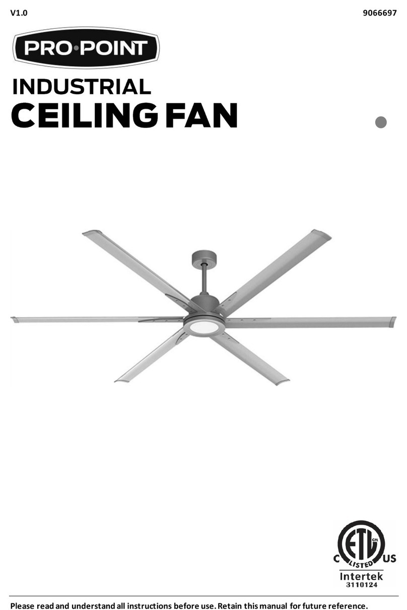
84 IN. INDUSTRIAL CEILING FAN

8676934 84 IN. INDUSTRIAL CEILING FAN V1.2
2 For technical questions call 1-800-665-8685
SPECIFICATIONS
Size 84 in.(213.36 cm)
Downrod Length
9 in. (22.86 cm)
Downrod Diameter 3/4 in. (1.90 cm)
Construction
Aluminum Blades
Number of Speeds 6 Speed Reversible
Voltage Rating 120V
Wattage Rating 35W
INTRODUCTION
Includes a remote control, an optional light kit and two 13 watt
CFL bulbs. Suitable for indoor use.
SAFETY
WARNING! Read and understand all instructions before using
this tool. The operator must follow basic precautions to reduce
the risk of personal injury and/or damage to the equipment.
Keep this manual for safety warnings, precautions, operating or
inspection and maintenance instructions.
HAZARD DEFINITIONS
Please familiarize yourself with the hazard notices found in this
manual. A notice is an alert that there is a possibility of property
damage, injury or death if certain instructions are not followed.
84 IN. INDUSTRIAL CEILING FAN

V1.2 84 IN. INDUSTRIAL CEILING FAN 8676934
Visit www.princessauto.com for more information 3
DANGER! This notice indicates an immediate and specific
hazard that will result in severe personal injury or death if the
proper precautions are not taken.
WARNING! This notice indicates a specific hazard or unsafe
practice that could result in severe personal injury or death if
the proper precautions are not taken.
CAUTION! This notice indicates a potentially hazardous
situation that may result in minor or moderate injury if proper
practices are not taken.
NOTICE! This notice indicates that a specific hazard or unsafe
practice will result in equipment or property damage, but not
personal injury.
WORK AREA
1. Operate in a safe work environment. Keep your work area
clean, well-lit and free of distractions.
2. Keep anyone not wearing the appropriate safety
equipment away from the work area.
3. Store tools properly in a safe and dry location. Keep tools
out of the reach of children.
4. Do not install or use in the presence of flammable gases,
dust or liquids.
PERSONAL SAFETY
WARNING! Wear personal protective equipment approved by
the Canadian Standards Association (CSA) or American
National Standards Institute (ANSI).
PERSONAL PROTECTIVE EQUIPMENT
1. Always wear impact safety goggles that provide front and
side protection for the eyes. Eye protection equipment
should comply with CSA Z94.3-07 or ANSI Z87.1 standards
based on the type of work performed.

8676934 84 IN. INDUSTRIAL CEILING FAN V1.2
4 For technical questions call 1-800-665-8685
2. Wear gloves that provide protection based on the work
materials or to reduce the effects of tool vibration.
3. Wear protective clothing designed for the work
environment and tool.
4. Non-skid footwear is recommended to maintain footing
and balance in the work environment.
PERSONAL PRECAUTIONS
Control the tool, personal movement and the work
environment to avoid personal injury or damage to the tool.
1. Do not operate any tool when tired or under the influence
of drugs, alcohol or medications.
2. Avoid wearing clothes or jewelry that can become
entangled with the moving parts of a tool. Keep long hair
covered or bound.
3. Do not overreach when operating the tool. Proper footing
and balance enables better control in unexpected situations.
SPECIFIC SAFETY PRECAUTIONS
WARNING! DO NOT let comfort or familiarity with product
(gained from repeated use) replace strict adherence to the
tool safety rules. If you use this tool unsafely or incorrectly,
you can suffer serious personal injury.
1. Use the correct tool for the job. This tool was designed for
a specific function. Do not modify or alter this tool or use it
for an unintended purpose.
2. Ensure that the installation site is clear of obstructions and that
the rotating blades do not come in contact with any object.
Install the blades 10 ft (3 m) away from the floor.
3. Mount the fan on a ceiling joist if possible; the joist must be
able to support the weight of the moving fan. If mounting
on a ceiling outlet box, use a 4 x 2-1/8 in. deep, metal
octagon box that is UL-listed as suitable for fan use and

V1.2 84 IN. INDUSTRIAL CEILING FAN 8676934
Visit www.princessauto.com for more information 5
capable of supporting 35 lb (15.87 kg) or less. Use the
mounting hardware provided with the outlet box.
4. Only use UL/ETL listed light kits if installing kits that are
not provided with the fan. Refer to the kit's manual for
installation procedures. Disconnect the fan from the supply
circuit before installing the light kit to prevent
electric shock.
5. Protect the fan motor housing's finish by keeping the part
in the packaging until it is ready for installation.
6. Do not attach the fan blades before mounting the fan
motor housing. If installing more than one ceiling fan, do
not mix the blade sets.
7. Do not bend the blade brackets while installing or cleaning
the fan to prevent personal injury.
8. Do not use solid-state speed control devices with the fan to
prevent fire or electrical hazards and personal injury.
9. Ensure that all connections are secure once the fan is
mounted to prevent it from falling and causing damage
and/or personal injury.
10. The fan is pre-lubricated and ready for use after
installation. Further lubrication is not necessary.
11. Turn the fan off and allow the blades to fully stop before
reversing the fan direction.
ELECTRICAL SAFETY
WARNING! Do not touch or handle a live tool with any part of
your body that is wet or damp. Wet skin reduces resistance to
electrical current, increasing the danger of a serious or
fatal shock.
1. Protect yourself against electric shocks when working on
electrical equipment. Avoid body contact with grounded
surfaces. There is an increased chance of electrical shock if
your body is grounded.

8676934 84 IN. INDUSTRIAL CEILING FAN V1.2
6 For technical questions call 1-800-665-8685
2. Do not expose the tool to rain or wet conditions. Water
entering a power tool will increase the risk of electric shock.
3. Do not alter any parts of the tool or accessories. All parts
and accessories are designed with built-in safety features
that may be compromised if altered.
4. Make certain the power source conforms to requirements
of your equipment (see Specifications).
5. When wiring an electrically driven device, follow all
electrical and safety codes, as well as the most recent
Canadian Electrical Code (CE) and Canadian Centre for
Occupational Health and Safety (CCOHS).
WARNING! All wiring should be performed by a
qualified electrician.
UNPACKING
WARNING! Do not operate the tool if any part is missing.
Replace the missing part before operating. Failure to do so
could result in a malfunction and personal injury.
Remove the parts and accessories from the packaging and inspect
for damage. Make sure that all items in the parts list are included.
ASSEMBLY & INSTALLATION
Numbered references in parenthesis (#1) refer to the included
Parts List. Dashed numbers in parenthesis (Fig. 1-1) refer to a
specific point in an illustration or image.
HANGING THE SYSTEM
WARNING! Switch off the appropriate circuit breakers at the
electrical panel before starting to avoid electrical shock.
WARNING! Use an outlet box that can support up to 35 lb
(15.87 kg) to prevent the fan from falling and causing damage
and/or personal injury

V1.2 84 IN. INDUSTRIAL CEILING FAN 8676934
Visit www.princessauto.com for more information 7
1. Attach the
mounting
bracket (#1) to the
outlet box (not
included) using the
appropriate
hardware.
See Fig. 1.
2. Remove the cross
pin (Fig. 2-1) and
cotter pin (Fig. 2-2)
from the
downrod (Fig. 2-3).
3. Loosen the two downrod jam
screws (Fig. 3-1). Ensure that
the hex nut (Fig. 3-2) is on the
side of the set screw head.
4. Insert the yoke cover (Fig. 4-1),
deco ring and canopy (Fig. 4-2)
onto the downrod.
Fig. 4
Fig. 5
Fig. 6
Fig. 3
Fig. 1
Fig. 2

8676934 84 IN. INDUSTRIAL CEILING FAN V1.2
8 For technical questions call 1-800-665-8685
5. Feed the motor lead wires (Fig. 5-1) through the downrod.
Insert the downrod assembly into the yoke (Fig. 5-2). Insert
the cross pin (Fig. 5-3) from Step 2 through the yoke and
downrod. Secure with the cotter pin (Fig. 5-4) from Step 2.
6. Tighten the two downrod jam screws
(Fig. 6-1). Secure by using a wrench to
tighten the hex nut (Fig. 6-2). Pull down
the yoke cover (Fig. 6-3) to cover
the yoke.
7. Lift the fan assembly (#5) onto the
mounting bracket. See Fig. 7.
8. Rotate the fan until the ball groove (Fig.
8-1) engages the ridge (Fig. 8-2) in the
mounting bracket.
CONNECTING THE WIRES
1. Assemble the wood screw (#14), spring washer (#12), flat
washer (#11) and safety cable as shown in Fig. 7-1. Secure
the wood screw to the ceiling joist through any available
slot on the mounting bracket. Tighten the safety cable.
2. Connect the electrical wires by following the diagram
below. Ensure that all exposed wires are secured inside wire
connectors or a terminal block.
Fig. 7
Fig. 8

V1.2 84 IN. INDUSTRIAL CEILING FAN 8676934
Visit www.princessauto.com for more information 9
2.1 Connect the white wire from the house to the white
wire from the fan.
2.2 Connect the black wire from the house to the black
wire from the fan.
2.3 Connect the ground wire from the house to the green
wires from the downrod and the mounting bracket.
2.4 Secure the ends together using the provided twist-on
wire connectors (#18).
2.5 Push the wires gently into the junction box with the
wire connectors pointing upwards.
INSTALLING THE
CANOPY
1. Push the canopy up until the two
screws (pre-screwed on the
mounting bracket) are engaged with
the two keyholes (Fig. 9-1) on
the canopy.
2. Rotate the canopy slightly until the
screw heads are engaged in the
narrow end of the keyholes.
3. Tighten both screws.
Fig. 9

8676934 84 IN. INDUSTRIAL CEILING FAN V1.2
10 For technical questions call 1-800-665-8685
INSTALLING THE BLADES
Attach the blades (#6) to the fan assembly (#5) using the flat
washers (#11) and the blade screws (#15).
INSTALLING THE LIGHT KIT
Fig. 11
Fig. 12
Fig. 13
1. Install the bulbs (#7) to the medium base sockets (Fig. 11-1).
2. Attach the glass shade (#8) by screwing it onto the light kit
pan clockwise. See Fig. 12.
IMPORTANT! If you are not installing the provided light kit,
attach the bottom plate (#9) instead of the glass shade to the
pan. See Fig. 13.
Fig. 10

V1.2 84 IN. INDUSTRIAL CEILING FAN 8676934
Visit www.princessauto.com for more information 11
SETTING THE REMOTE
AUTOMATIC SETUP
The fan comes with a learning remote for easy setup.
1. Remove the battery cover (Fig. 14-1).
2. Install the provided 12V 23AE battery (Fig. 14-4).
3. Switch the circuit breakers on.
4. Point the remote towards the fan and press the
ON/OFF switch.
IMPORTANT! If the fan does not respond to the remote,
perform Step 6 of Manual Setup (See next section).
5. Install the battery cover.
MANUAL SETUP
1. Remove the battery
cover (Fig. 14-1).
2. Set a code for the fan
by sliding the switches
(Fig. 14-2) using a
small screwdriver or a
ballpoint pen. There
are four switches and
16 possible combinations. If installing multiple fans, set a
unique code for each.
3. Set the dimming switch (Fig. 14-3).
3.1 Set the switch to ON if using CFL bulbs.
3.2 Set the switch to D if using incandescent bulbs.
4. Install the provided 12V 23AE battery (Fig. 14-4).
5. Switch the circuit breakers on.
Fig. 14

8676934 84 IN. INDUSTRIAL CEILING FAN V1.2
12 For technical questions call 1-800-665-8685
6. Press the SET button (Fig. 15-1)
for 3 to 5 seconds. The fan will
start its programming cycle
and do the following:
6.1 Rotate clockwise for
2-1/2 minutes.
6.2 Stop.
6.3 Rotate counterclockwise
for 2-1/2 minutes.
6.4 Stop.
The programming cycle will complete after five minutes
and the remote will be ready for use. If the fan does not
respond to the remote, switch off the circuit breakers and
wait for ten seconds before turning them back on. Repeat
step 6 until the remote is programmed successfully.
7. Install the battery cover.
INSTALLING MULTIPLE FANS
Multiple fans within the same area can respond to a single
remote due to frequency interference or improper installation.
Follow these steps to ensure that each fan is controlled by its
own remote.
1. Install the first fan and set the remote. Ensure that the fan
and remote are operating properly.
2. Install the second fan but do not set the remote yet.
3. Lower the canopy of the first fan and disconnect the black
wires. Attach the wire connector to the black wire from the
house. The first fan will remember its current setting.
4. Set the second fan’s remote. Ensure that you are using a
code that is different from the first one.
Fig. 15

V1.2 84 IN. INDUSTRIAL CEILING FAN 8676934
Visit www.princessauto.com for more information 13
5. Once the second fan’s remote has been programmed,
switch off the circuit breakers. Reconnect the black wires
on the first fan and secure using the wire connector.
6. Switch on the circuit breakers. Each fan should respond to
its own remote.
OPERATION
REMOTE INTERFACE
A. Speed Dial (6 Speeds)
B. Fan ON/OFF Switch
C. Reverse Button
D. Light Switch
•ON/OFF for CFL Bulbs
•Dimming for Incandescent Bulbs
CARE & MAINTENANCE
1. Maintain the tool with care. A tool in good condition is
efficient, easier to control and will have fewer problems.
2. Inspect the tool components periodically. Repair or replace
damaged or worn components. Only use identical
replacement parts when servicing.
3. Only use accessories intended for use with this tool.
4. Maintain the tool’s labels and name plates. These carry
important information. If unreadable or missing, contact
Princess Auto Ltd. for replacements.
WARNING! Only qualified service personnel should repair the
tool. An improperly repaired tool may present a hazard to the
user and/or others.
Fig. 16

8676934 84 IN. INDUSTRIAL CEILING FAN V1.2
14 For technical questions call 1-800-665-8685
CLEANING
Wipe the surface with a clean, moist cloth. Do not use solvents.
DISPOSAL
Recycle a tool damaged beyond repair at the appropriate facility.
TROUBLESHOOTING
Visit a Princess Auto Ltd. location for a solution if the tool does
not function properly or parts are missing. If unable to do so,
have a qualified technician service the tool.

V1.2 84 IN. INDUSTRIAL CEILING FAN 8676934
Visit www.princessauto.com for more information 15
PARTS BREAKDOWN

8676934 84 IN. INDUSTRIAL CEILING FAN V1.2
16 For technical questions call 1-800-665-8685
PARTS LIST
# DESCRIPTION QTY
1 Mounting Bracket 1
2 Downrod 1
3 Canopy 1
4 Yoke Cover 1
5 Fan Assembly 1
6
Extruded Aluminium Blades
6
7 13W CFL Bulb 2
8 Glass Shade 1
9 Bottom Plate 1
10 Remote 1
11 Flat Washer for Mounting Plate
Flat Washer for Blades
3
19
12 Spring Washer 3
13 Machine Screw 2
14 Wood Screw for Mounting Plate
Wood Screw for Remote
3
2
15 Blade Screw 19
16
Balanced Slide
1
17 Weight Block (3 g) 3
18 Wire Connector 3

V 1,2 8676934
Vous devez lire et comprendre toutes les instructions avant d'utiliser
l'appareil. Conservez ce manuel afin de pouvoir le consulter plus tard.
MANUEL D'UTILISATEUR
VENTILATEUR DE PLAFO
ND DE
84 PO DE QUALITÉ IND
USTRIELLE

8676934 VENTILATEUR DE PLAFOND DE 84 PO V 1,2
DE QUALITÉ INDUSTRIELLE
2 En cas de questions techniques, appelez le 1-800-665-8685
SPÉCIFICATIONS
Taille
213,36 cm (84 po)
Longueur de la tige de descente 22,86 cm (9 po)
Diamètre de la tige de descente
1,90 cm (3/4 po)
Construction Lames en aluminium
Nombre de vitesses
6 vitesses réversible
Tension nominale 120 V
Courant nominal
35 W
INTRODUCTION
Comprend une télécommande, une trousse de lampe en option,
ainsi que deux ampoules LFC de 13 W. Convient pour usage
à l’intérieur.
SÉCURITÉ
AVERTISSEMENT ! Veuillez lire et comprendre toutes les
instructions avant d'utiliser cet outil. L'utilisateur doit respecter
les précautions de base lorsqu'il utilise cet outil afin de réduire
le risque de blessure ou de dommage à l'équipement.
Conservez ce manuel qui contient les avertissements de
sécurité, les précautions, les instructions de fonctionnement ou
d'inspection et d'entretien.
VENTILATEUR DE PLAFO
ND DE
84 PO DE QUALITÉ IND
USTRIELLE

V 1,2 VENTILATEUR DE PLAFOND DE 84 PO 8676934
DE QUALITÉ INDUSTRIELLE
Visitez www.princessauto.com pour plus d'informations 3
DÉFINITIONS DE DANGER
Veuillez-vous familiariser avec les avis de danger qui sont
présentés dans ce manuel. Un avis est une alerte indiquant qu'il
existe un risque de dommage à la propriété, de blessure ou de
décès si on ne respecte pas certaines instructions.
DANGER ! Cet avis indique un risque immédiat et particulier
qui entraînera des blessures corporelles graves ou même la
mort si on omet de prendre les précautions nécessaires.
AVERTISSEMENT ! Cet avis indique un risque particulier ou
une pratique non sécuritaire qui pourrait entraîner des
blessures corporelles graves ou même la mort si on omet de
prendre les précautions nécessaires.
ATTENTION ! Cet avis indique une situation possiblement
dangereuse qui peut entraîner des blessures mineures ou
modérées si on ne procède pas de la façon recommandée.
AVIS ! Cet avis indique un risque particulier ou une pratique
non sécuritaire qui entraînera des dommages au niveau de
l'équipement ou des biens, mais non des blessures corporelles.
AIRE DE TRAVAIL
1. Travaillez dans un environnement de travail sécuritaire.
Gardez votre aire de travail propre, bien éclairée et
exempte de toute distraction.
2. Assurez-vous que les personnes qui ne portent pas
l'équipement de sécurité approprié ne se trouvent pas à
proximité de l'aire de travail.
3. Rangez les outils correctement dans un lieu sécurisé et sec.
Gardez les outils hors de la portée des enfants.
4. N'installez pas et n'utilisez pas d'outils électriques en
présence de gaz, de poussière ou de liquides inflammables.

8676934 VENTILATEUR DE PLAFOND DE 84 PO V 1,2
DE QUALITÉ INDUSTRIELLE
4 En cas de questions techniques, appelez le 1-800-665-8685
SÉCURITÉ PERSONNELLE
AVERTISSEMENT ! Portez de l'équipement de protection
personnelle homologué par l'Association canadienne de
normalisation (CSA) ou l'American National Standards
Institute (ANSI).
ÉQUIPEMENT DE PROTECTION PERSONNELLE
1. Portez toujours des lunettes antiprojections qui offrent une
protection frontale et latérale pour les yeux. L'équipement de
protection des yeux devrait être conforme à la norme CSA
Z94.3-07 ou ANSI Z87.1 fonction du type de travail effectué.
2. Portez des gants qui protègent en fonction des matériaux
de travail et pour réduire les effets des vibrations de l'outil.
3. Portez des vêtements de protection conçus pour
l'environnement de travail et pour l'outil.
4. Les chaussures antidérapantes sont recommandées pour
maintenir la stabilité et l'équilibre au sein de
l'environnement de travail.
PRÉCAUTIONS PERSONNELLES
Gardez le contrôle de l'outil, de vos mouvements et de
l'environnement de travail pour éviter les blessures ou le bris
de l'outil.
1. N'utilisez pas l'outil si vous êtes fatigué ou sous l'effet de
drogues, d'alcool ou de médicaments.
2. Évitez de porter des vêtements ou des bijoux pouvant se
prendre dans les pièces mobiles d'un outil. Gardez les
cheveux longs recouverts ou attachés.
3. N'utilisez pas l'outil si vous devez étirer les bras pour vous
en servir. Une stabilité et un équilibre appropriés sont
nécessaires afin d'avoir un meilleur contrôle en cas de
situations inattendues.
Table of contents
Languages:
Other PROPOINT Fan manuals