ProSpot Fitness PBL-21 User manual

Pno$P
olfitnessrM
ModerPBL-2
I
Owners
Manual
1)AssemblyInstructions/Illustrations
2)UseandOperationofPnoSyorJitnessrM
Product
3)Maintenance
ofyourPnoSrorJitnessru
Product
4)WarrantyInformation
5)PartsList
Serial#:
ilililililtilil]It|ilIilil|il|ilililltiilililililI|il
13506D001
83PBL-21
Table
ofContents
Assemblylnstructions. .............1-4
UseandOperation
ofYourPROSPOT/rnessrM
Product.
....
........
......
..5
Periodic
Maintenance
of
your
PROSPOVtnessrM
Product.
....
......
.......6
Wa:ranty
Information ................7
Parts
List.... ..................8
L-serlnstructions......... ..........9-15
lnstructibnsforAssembly
ofthePROSPOTfitnessrM
PBL-21
Beforeassembly,choosea safe
locationforyourPROSPOTfituessrM
PBL-21 ThePROSPOTlrzessrM
PBL-21
hasa footprintof approximately
6x 3 Locate
your
PROSPOTttnessrM
PBL-21away
from
any
source
ofwater.
Approximateassemblytimeis
1/2hours.
Aflatareaof6'
x4'will
be
requiredtoassemble
and
properly
use'thePROSPOTfitnessrM
PBI-21
You
willneedthefollowingtoolsandahelpertocompletetheassembly:
o 14mmBoxEndWrench
o 17mmBoxEndWrench
Floor
Padding,suchascardboard,toavoid
scratching
your
floorduringassembly.
Agoodpair
ofscissorswilibehelpful
inseparatingthe
parts
fromoneanother
whileremoving
them
from
thecartons.
Beforeassembly,separateandidentifytheright-sided
parts
fromtheleft-sided
parts.
These
parts
are
easilydistinguishedbythemanner
inwhichthe
pre-drilled
holes
align
with
corresponding
parts,
orare
identifiedby
"L"&"R'stickers.
The
PROSPOTrrressrM
PBL-21
uses
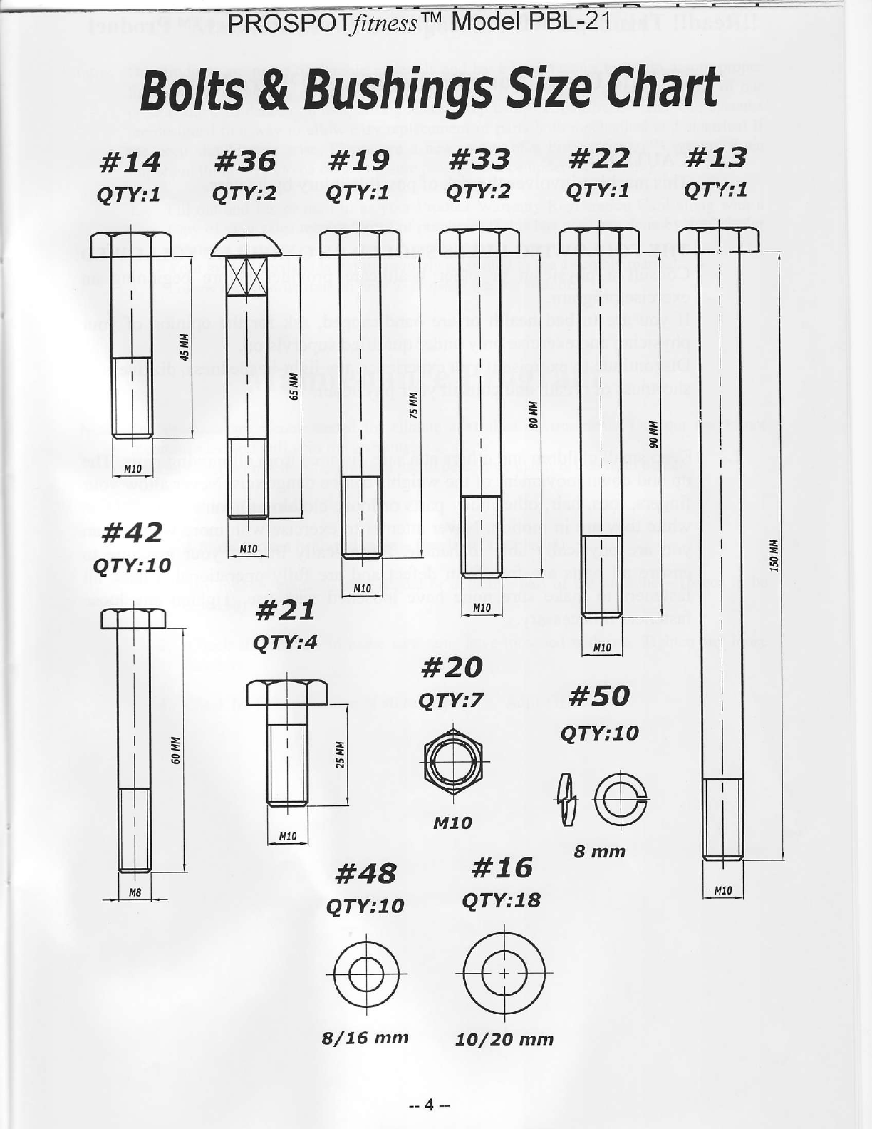
severaldifferentlengthsof bolts.Becarefulto usethecorrect
lengthofboltcalledforateachstep
ofassembly.Refertothesizingcharts
provrded
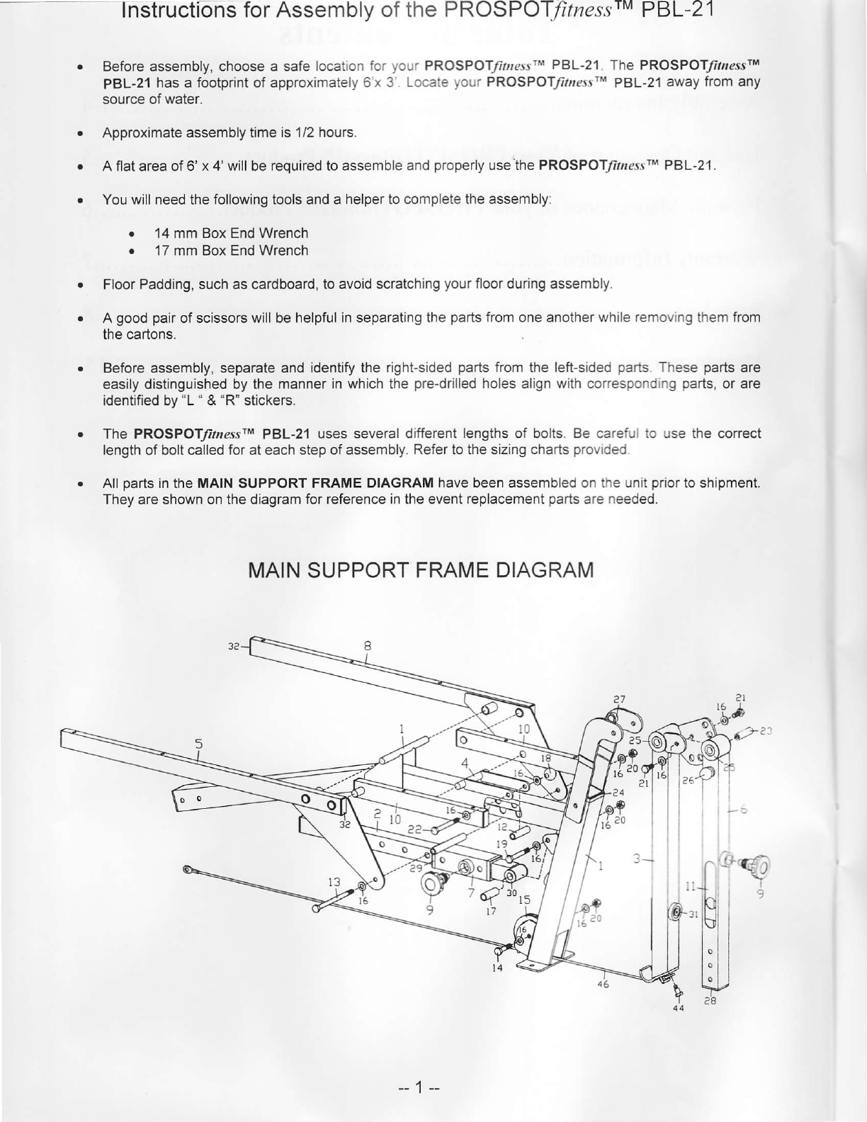
All
parts
intheMAINSUPPORTFRAME
DIAGRAMhavebeenassembledontheunit
prior
toshipment.
Theyareshownonthediagram
forreferenceintheeventreplacement
parts
are
needed.
MAINSUPPORT
FRAMEDIAGRAM
toc
I
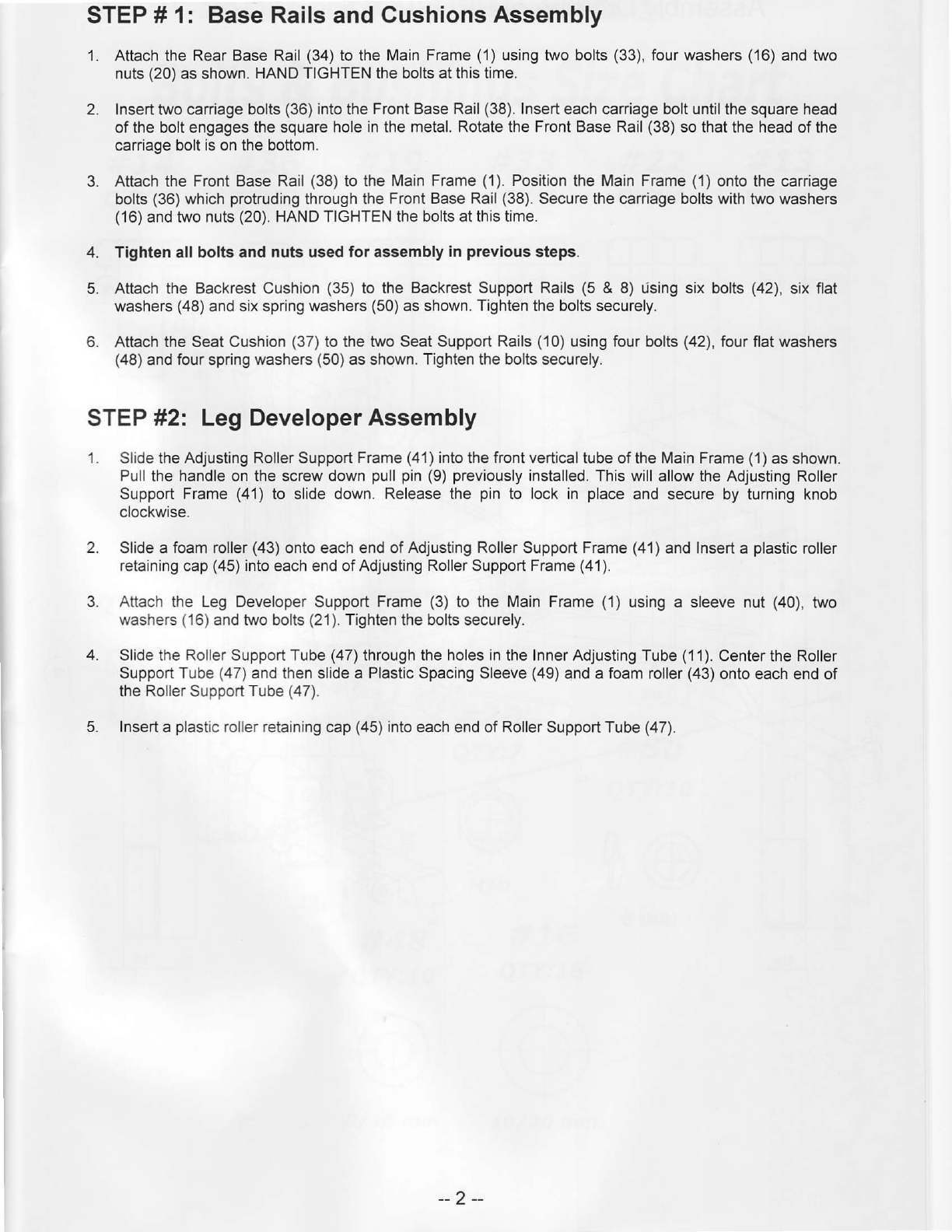
STEP# 1: BaseRailsand
CushionsAssembly
1. AttachtheRearBaseRail
(34)
tothe
MainFrame
(1)
usingtwobolts
(33),
fourwashers
(16)
andtwo
nuts
(20)
as
shown.
HANDTIGHTENtheboltsatthis
time.
2. Insert
two
carriagebolts
(36)
intotheFront
BaseRail
(38).
Insert
eachcarriageboltuntilthesquarehead
oftheboltengages
thesquare
holein
the
metal.RotatetheFrontBaseRail
(38)
sothattheheadof
the
carriage
boltisonthebottom
3. AttachtheFront
BaseRail
(38)
totheMain
Frame
(1).
Position
theMainFrame
(1)
ontothe
carriage
bolts
(36)
which
protruding
throughthe
FrontBaseRail
(38).
Securethe
carriage
bolts
withtwowashers
(16)
andtwonuts
(20).
HAND
TIGHTENtheboltsatthistime.
4. Tightenallboltsandnutsusedforassembly
inprevious
steps.
5. AttachtheBackrest
Cushion
(35)
to theBackrestSupportRails
(5& 8) Usingsixbolts
(42),
sixflat
washers
(48)
and
sixspringwashers
(50)
asshown.
Tighten
theboltssecurely.
6. AttachtheSeatCushion
(37)
tothetwo
SeatSupportRails
(10)
usingfour
bolts
(42),
fourflatwashers
(48)
andfourspring
washers
(50)
as
shown.
Tightentheboltssecurely.
STEP
#2: LegDeveloperAssembly
1. Slide
the
AdjustingRollerSupportFrame
(41)
lntothefrontverticaltube
oftheMainFrame
(1)
asshown.
Pull
the
handleonthe
screw
down
pull
pin
(9)
previously
installed.Thiswill
allowtheAdjustingRoller
Support
Frame
(41)
to slidedown.
Releasethepinto lockin place
andsecureby turning
knob
clockwise.
2. Slideafoam
roller
(43)
ontoeachendof
AdjustingRoller
Support
Frame
(41
)andlnsert
aplastic
roller
retaining
cap
(45)
intoeachendofAdjusting
Roller
Support
Frame
(4'1).
3. Attachthe LegDeveloperSupportFrame
(3)
to theMainFrame
(1)usinga sleevenut(40),
two
washers
(16)
andtwobolts
(21).
Tightentheboltssecurely.
4. SlidetheRollerSupportTube
(47)
throughtheholesin
the
Inner
AdjustingTube
(11).
CentertheRoller
SupporiTube
(47)
andthenslidea PlasticSpacingSleeve
(49)
andafoam
roller
(43)
onto
eachendof
theRoller
Support
Tube
(47).
5. Insert
aplastic
rollerretaining
cap
(45)
into
eachendof
Roller
SupportTube
(47).
--2--
42
33
--3--
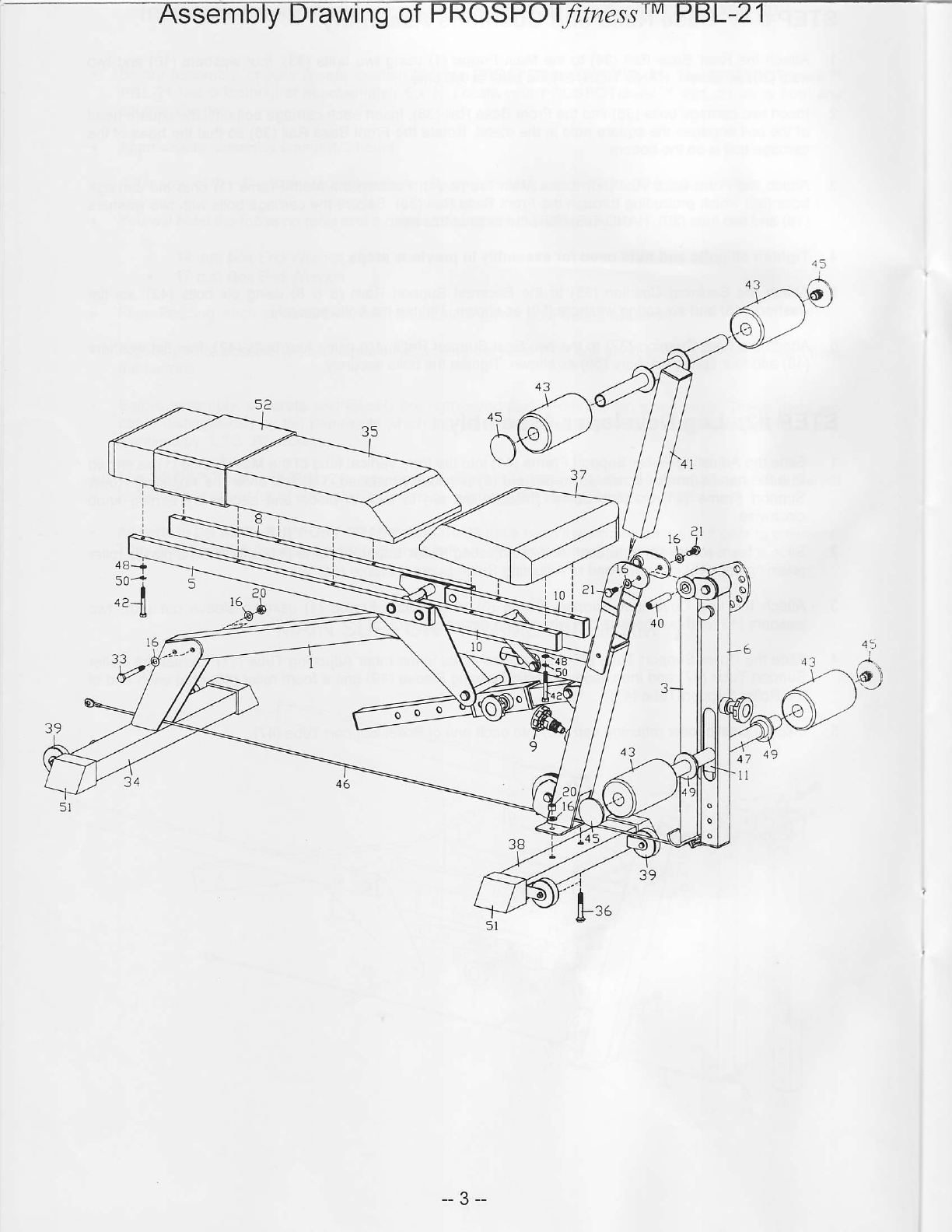
FROSF6
i:i;;; '-
Bolts
&
Bushings
Size
Chart
#74 #36 #79 #33 #22 #73
QTY:7 QTY:2 QTY:I QTY:2 QTY:I QT'/:7
#42
QTY:7O #27
QTY:4 #20
QTY:7 #50
QTY:7O
n/A
TV
8mm
#48
QTY:7O #76
QTY:78
8/76 mm 7O/2O
mm
--4--
!lRead!!
ThisPageBeforeUsing
YourProSpotlitness
rM
Product
SafeUseof Your ProSpotJitne,s,rrMProduct
CAUTION:
Thismachineinvolvesthe
riskofpossible
injury
byitsuser.
THE FOLLOWING RULES SHOULD BE CARFULLY FOLLOWED:
Consult a physician or other healthcareprovider before beginning an
exercise
program.
If you are in bad health or are handicapped,ask for the opinion of your
physician
andexerciseonly under
qualifiedsupervision.
Discontinueto exercise
if you experienceanylighrheadedness,
dizziness
or
shortnessofbreath and
consult
yourphysician.
Keepsmallchildrenandothersatasafedistancefrom all rnovingparts.
The
up anddownmovementof theweights
canbedangerous.Neverallow your
fingers,toes,hair, otherbody partsor looseclothing to comenear
weights
while they arein motion.Never attemptto exercisewith moreweightthan
you are physically able to handle.Periodically inspectyour machineto
ensureall partsare free from defectand are fully operational.Check all
fastenersto make surenone have loosenedwith use.Tighten any loose
fastenersif necessary.
1.
,
--5--
MaintenanceofProSpoffitnes{MProduct
Intro: Our products
aremadeof durablematerialsandhavebeenfactory testedto assure
proper
function andreliability. Along with our EquipmentWarranty,this givesthe owner of our
product
theconfidenceof along lasting
relationshipwith ProSpotffzessrMInc. Our systems
aredesignedin a way to allow easy
replacementof partsboth mechanicalandelectricalif
the needshould ever arise.If you are a new owner of a ProSpofinessrM system,
three
importantthings
needto bedoneto assure
promptserviceunderthewarranty:
1. Fill out andfax or mail to us your ProductWarrantyRegistration
Card alongwith a
copyof your salesreceipt(proofof purchase)
if this hasnot beendoneby your dealer
attimeof purchase.
2. Your system
needs
to beset
upproperly
according
to theassemblymanual.
3. Follow userinstructionsonhow to properly
usethesystem.
MaintenanceProgram
Note: Our productsare recommendedfor climate controlled environments.
Outdoor use is not
recommendedandwill void thewarranty.
Carefullyinspectmachinebeforeeachuseto determine
thatit is freefrom defects.
Do NOT usemachineif youfind:
1. A loose,brokenor frayedcable
- (needs
to bereplaced)
2. Any broken,cracked,tom, frayed or defectivepart of the machine
- (needs
to be
replaced)
3. Checkall fastenersto makesurenonehaveloosened
with use.Tighten any loose
fasteners.
4. Checkforfreemovementofallcable
pulleys.
Adjustif necessary.
--6--

WarrantvInformation
EachPnoSror/rzessruProduct
comes
with alimitedparts
replacement
warranty.Please
referto the
actual
warrantycardincludedwith your systemfor specificcoverage.If you haveanyquestions
about
performance
underthislimitedwananty,
please
writeusat:
PnoSrofflzess, Inc.
Attn: WarrantyService
1325OakbrookDrive.
Suite
E
Norcross,GA30093
Office
(770\446-9299
Fax (770\-446-7213
I
I
I
--7 --
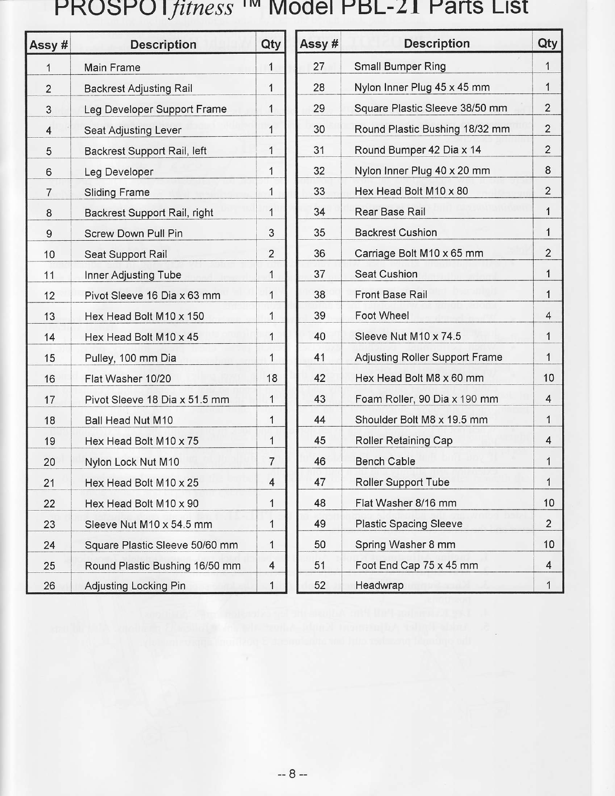
PKOSPOlJitness'
.'v'
Model H6L-Zl YaftSLlSt
Assy#Description Qtv
1MainFrame 1
Backrest
AdiustingRail 1
Leg
DeveloperSupport
Frame 1
4SeatAdiusting
Lever
Backrest
SupportRail,
left
6LegDeveloper
7SlidinqFrame
8BackrestSupport
Rail,right
IScrewDownPullPin
10 Seat
SupportRail 2
11 lnnerAdiusting
Tube 1
tz PivotSleeve16Diax63mm 1
42. HexHeadBoltM10
x150 1
14 HexHeadBoltM10x45 1
15 Pullev,100mmDia 1
16 FlatWasher10/20 18
PivotSleeve18Diax 51
.5mm 1
18 BallHeadNutM10 1
19 HexHeadBoltM10x 75 1
20 NylonLockNutM10 7
21 HexHeadBoltM10
x25 4
22 HexHeadBoltM10x 90 1
z5 SleeveNutM10x54.5mm 1
24 SouarePlastic
Sleeve50/60mm 1
IJ RoundPlasticBushing16/50
mm 4
zo AdiustingLockingPin 1
Assy# Description Qtv
27 Small
BumperRing 1
28 Nvlon
InnerPlug45x45mm I
ZY SouarePlasticSleeve
38/50mm
1n Round
PlasticBushing18/32mm
3'l RoundBumoer42Diax 14 2
JZ NvlonInner
Pluq40x20mm 8
JJ HexHeadBoltM10x80 2
34 RearBaseRail I
35 BackrestCushion 1
CaniaoeBoltM
10x65mm 2
37 SeatCushion 1
38 FrontBaseRail 1
FootWheel 4
40 SleeveNutM10x74.5 1
41 AdiustingRoller
SupportFrame 1
42 HexHeadBoltM8x60mm 10
43 FoamRoller,90Diax190mm 4
44 ShoulderBoltM8x 19.5mm 1
,E. RollerRetaining
Cap 4
46 Bench
Cable 1
47 RollerSupportTube 1
48 FlatWasher8/16mm 10
49 PlasticSpacing
Sleeve
50 SpringWasher8mm 10
51 FootEnd
Cap75x45mm ,
JI Headwrap 1
--8--
PBL-2I
PROSPOT
FITNESSTM
WeightBench
User
Instructions
The l,BL-21 PROSPOT FITNESSTM
weight benchhas been designed
with various adjustable
components
to provide the most personalizedand comfortable
benchpositionsfor your strength
trainingexercises.
Here are a few suggestions
on how to position the benchfor variousexercises.
Theseare only
suggestions,
however,and it is recommended
that you experiment
u,ith various bench
position
combinations
to find whatis comfortable
andconvenient
for you.
Note: All adjustment
knobs
lockwhenreleased
intotheirholes.By screwing
in theadjustment
knobs,
adjustablecomponents
(leg
extension.
benchseat,
benchbackand
anklerollers)are
tightened
into theirrespective
positions.While it is not necessary
to tightenadjustment
knobs,doing
sowill bolster
these
adjustablecomponents.
When
benchcable
is notattached
to lowerpulley
assembly,clip cableintocablekeeper
located
onrearbaserail,intheopening
ofthemainframe
support
post.
Whenperforming
'benching'exercises
(benchpress,
chest
press,
military press,
etc.)
positionthebenchso
thatit sits
backinside
theframe,
undemeaththebarbell.
When
positioning
bench
for exercises
thatuse
thelower
pulley
assembly,
attach
thebench
cable
tothe
lower
pulley
assembly
and
positionbenchsothatthebench
cableiscentered
in
theopening
of themainframe
support
post. Pull thebench
forwardsothattheattached
benchcable
istaut.
When
notin use,lower
theleg
extensionarm
andlock
in placewiththeLeg
ExtensionPull
Pin.
If you find thattheLeg Extension
Pull Pin is difficult to pull out,simply
raisethe leg
extension
armslightly
andthen
pulloutthe
pin.
Listedbelow
aretheadjustablecomponents
onthePBL-21. Firstlocateeach
adjusterknobor
leverand
thebenchcomponent
it controls.
l. Incline
Adjustment
Knotr: Adjusts
thebenchback
pad,
approximately
7positions'
2. Seat
Adjustment
Lever: Adjusts
thebench
seat,3positions.
3, KneeSupportAdjustment
Knob: Adjusts
thekneesupport
rollers,approximalely
4
positions.
4. LegExtensionPullPin:Adjusts
theleg
extensionarm,6positions
5. AnkleRoller
Adjustment
Knob:Adjuststhe
anklerollers,3
positions.
Alsoadjusts
the
optional
preacher
curl
barattachment,
3positions
approximately.
--9--

FlatBench
1. Position
theinclineadjustmentknobsothatthebenchback
pad
liesflat.
2. Place
theseatadjustmentleverinthethirdslotsothatthebenchseatliesflat.
3. Load
desiredweishtontothebarbelland
beein
vourexercise.
DeclineBench
1. Positionthe incline adjustmentknob to the lasthole, sothatthebenchis in the fuIl decline
position.
2. Placetheseatadjustmentleverintothefirst slot,sothatit alignswith thebenchback
pad.
3. UsingtheKneeSupportAdjustment Knob,adjustthekneerollers
to thehighestposition.
4. Using the Leg ExtensionPull Pin, position the leg extensionarm downward and lock in
placeinto the first or secondhole,whicheveris most comfortable
when ankles
areplaced
underanklerollers.
5. Make surebenchcableis attachedto lowerpulley assemblyandthatthere
is enoughweight
selectedon theweightstack,or placed
ontheweightplate
holder,
to holdyour legs
in place.
Pull benchforwardsothatthecable
istaut.
6. Loaddesired
weight ontothebarbeli,lay downon thebench,
placeyour ankles
beneath
the
anJ<le
rollersand
begin
your
exercise.
-- 10--
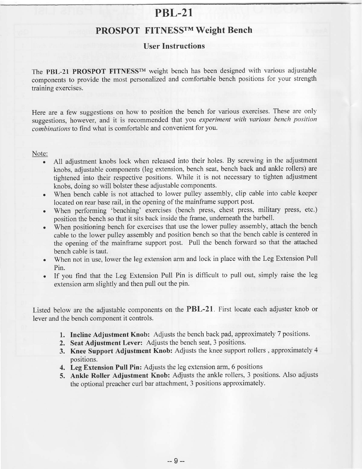
Incline Bench
i. Position
the inclineadjustment
knob into thefourth hole(approximately),
sothatthebench
back
padis in amoderately
uprightposition.
2. Placethe seatadjustment
lever into the middle slot. (Knee supportrollers can be in any
positionand
legextension
armshould
belockedin thelowerposition')
3. Loaddesired
weightontothebarbell
and
begin
yourexercise'
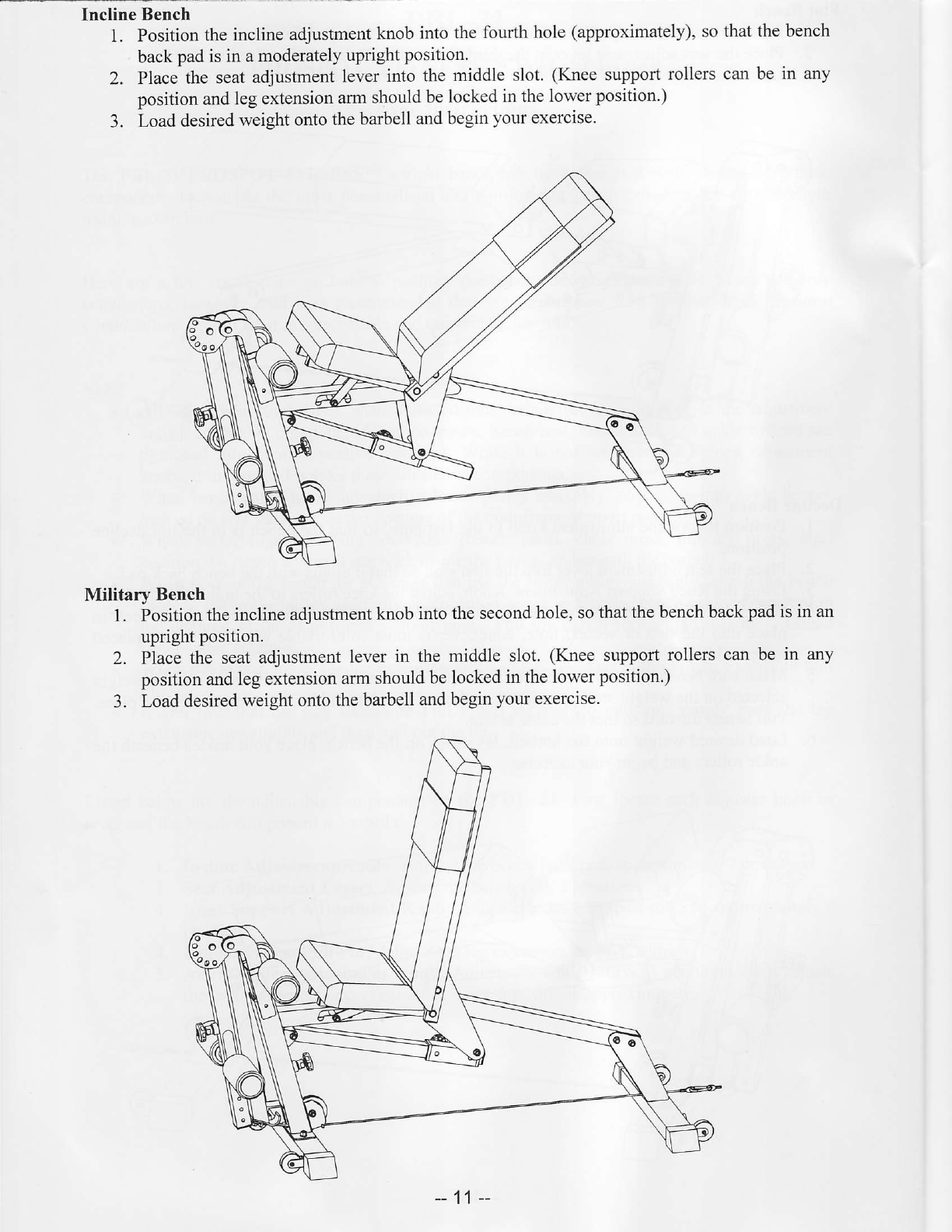
Military Bench
I. Positionthe
inclineadjustment
knobinto
thesecond
hole,sothat
thebenchback
pad
isin an
upright
position.
2. Place
the seatadjustment
leverin themiddleslot.(Knee
support
rollerscanbe in any
positionandlegextension
arm
shouldbe
locked
inthelower
position')
3. Load
desired
weightonto
thebarbell
andbegin
your
exercise.
11
2.
3.
5.
6.
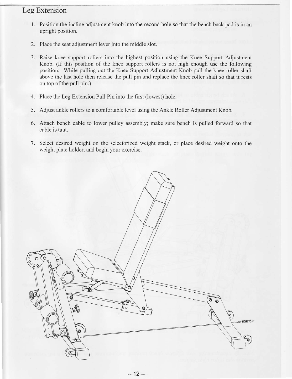
LesExtension
1Positiontheinclineadjustment
knobintothe
second
holeso
thatthebenchback
pad
isin an
upright
position.
Placetheseatadjustmentleverintothemiddleslot.
Raise
kneesupportrollersinto thehighest
position
usingthe KneeSupport
Adjustment
Knob.(If this position
of theknee
support
rollersis not highenoughusethe following
position:Whilepulling
outtheKree SupportAdjustmentKnob
pull theknee
rollershaft
abovethelastholethen
release
the
pullpin and
replace
thekneerollershaft
sothatit rests
ontopofthe
pullpin.)
PlacetheLegExtensionPullPinintothefirst(lowest)
hole.
Adjustankle
rollers
toacomfortable
level
usingtheAnkleRollerAdjustrnent
Knob.
Attachbench
cableto lowerpulleyassembly;
make
surebenchis pulled
forward
sothat
cableistaut.
7. Selectdesiredweight
on theselectorizedweight
stack,or place
desiredweight
ontothe
ueightplate
holder.
andbegin
your
exercise.
-12--
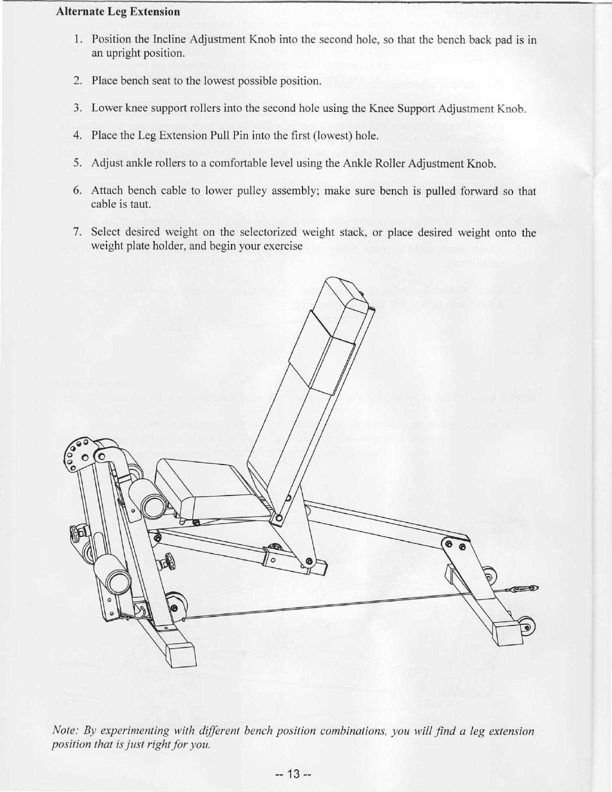
AlternateLegExtension
1. Position
theIaclineAdjustmentKnobintothesecond
hole,sothatthebench
back
pad
isin
anupright
position.
2. Placebenchseattothelowest
possibleposition.
3. Lowerkneesupportrollers
intothesecondholeusingthe
KneeSupportAdjustment
Knob.
4. Place
theLegExtensionPullPinintothefirst(lowest)
hole.
5. Adjust
ankle
rollers
toacomfortablelevelusingtheAnkle
RollerAdjustmentKnob.
6. Attach
benchcableto lowerpulleyassembly;make
surebenchis pulled
forward
sothat
cableistaut.
7. Selectdesiredweighton the selectorized
weightstack,or place
desiredweight
ontothe
weight
plate
holder,
andbegin
your
exercise
Note:By experimenting
u,ithdifferentbench
position
combinations,
youwillfind a legextension
positionthatis
just right
for you.
-- 13-
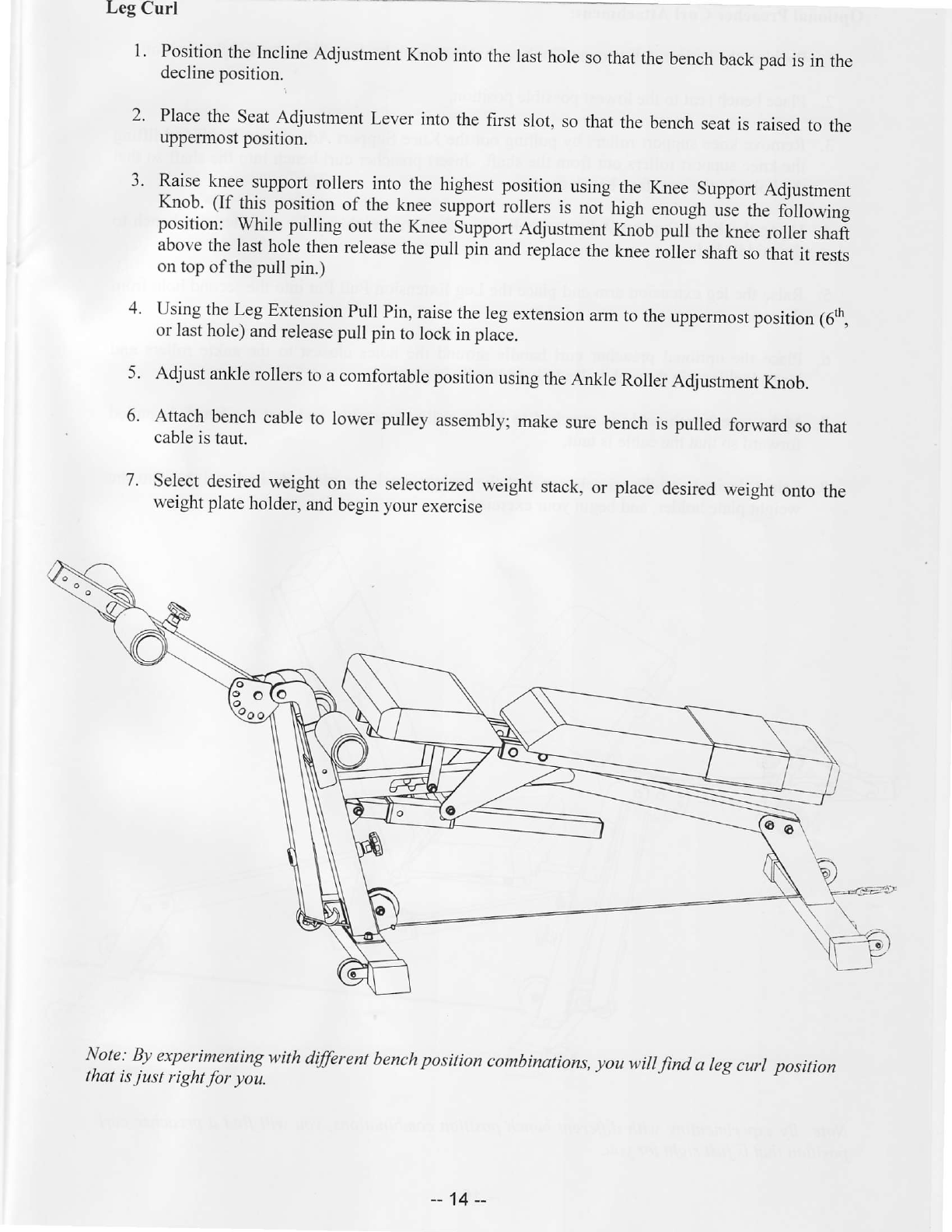
LegCurl
1. Position
the
Incline
Adjustment
Knob
intothelast
hole
sothat
the
bench
backpad
isin the
declineposition.
2. Place
theSeat
Adjustment
Leverintothefirst slot,
sothat
thebench
seat
is raised
to the
uppermostposition.
3. Raise
knee
support
rollers
into thehighestposition
using
theKneesupport
Adjustment
Knob.(If this position
of theknee
support
iollers is noi high"nough
urethefiitowing
position: while pullingoutthe
Knee
Support
Adjustment
Knob
pulfthe knee
rollershaft
above
thelast
hole
tlen release
the
pullpinand
replace
theknee
rollershaft
so
that
it rests
ontop
ofthepullpin.)
4. Using
theLeg
Extension
pullpin,raise
the
leg
extension
arm
totheuppermost
position
(6th,
orlast
hole)
and
releasepullpintolockinplace.
5. Adjust
ankle
rollers
toacomfortable
position
using
the
Arkle Roller
Adjustment
Knob.
6. Attach
bench
cable
to lowerpulleyassembly;
make
sure
bench
is pulled
forward
sothat
cable
istaut.
7. Select
desired
weighton theselectorized
weight
stack,
or place
desired
weight
ontothe
weightplate
holder,
and
begin
your
exercise
Note:Byexperimenting
withdffirent benchpositioncombinations,
youwiT
find areg
curr position
thatis
just right
for you.
-- 14--
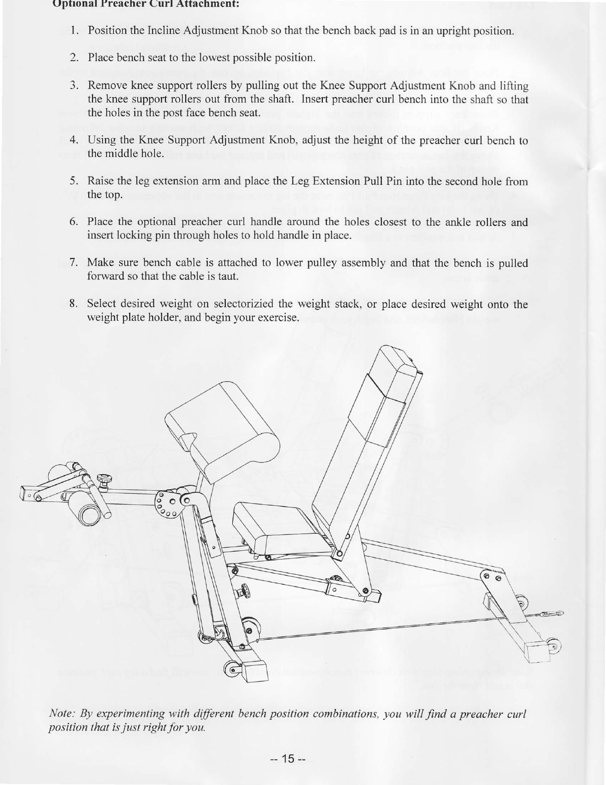
Uptronalf reachercurl Attachment:
1. PositiontheInclineAdjustmentKnobsothatthebench
back
pad
isinanupright
position.
2. Placebenchseattothelowest
possibleposition.
3. Removekneesupportrollersbypulling
outtheKnee
Support
Adjustment
Knob
andlifting
thekneesupportrollers
outfromthe
shaft.Insert
preacher
curlbenchintothe
shaftsothat
theholesinthe
post
face
benchseat.
4. UsingtheKneeSupportAdjustmentKnob,adjusttheheight
of thepreacher
curlbenchto
themiddlehole.
5. Raisethe
legextensionarmand
place
theLegExtensionPullPinintothesecondhole
from
thetop.
6. Placetheoptional
preacher
curl handlearoundtheholesclosest
to theanklerollers
and
insertlocking
pinthroughholestoholdhandleinplace.
7. Makesurebenchcableis attachedto lowerpulleyassemblyandthatthebenchis pulled
forwardsothatthecable
istaut.
8. Selectdesiredweight
on selectoriziedtheweightstack,or place
desiredweight
ontothe
weight
plate
holder,and
begin
your
exercise.
Note: By experimentingwith differentbench
position combinations,
you will find apreachercurl
positionlhqt is
just rightfor you.
-- 15--
Table of contents
Other ProSpot Fitness Home Gym manuals


