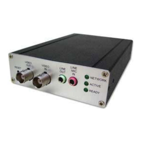
Provision ISR OC-RS-16 User manual

Ossia VMS-5000
OC-RS-16(3U) Ossia VMS Recording Server

Ossia VMS Enterprise User Manual
Contents
1Introduction ...................................................................................................................................................................1
1.1 Summary....................................................................................................................................................................1
1.2 Software Architecture ................................................................................................................................................1
1.3 System Components...................................................................................................................................................1
1.3.1 System.............................................................................................................................................................1
1.3.2 System Role....................................................................................................................................................2
2Hardware installation: ..................................................................................................................................................2
2.1 OC-RS-16 (3U) HW Installation: ..............................................................................................................................2
2.2 OC-RS-16 (3U) Disk Installation:..............................................................................................................................3
3Management Web-Client..............................................................................................................................................3
3.1.1 Network Config ..............................................................................................................................................3
3.1.2 Server Port Config ..........................................................................................................................................4
3.1.3 User Config.....................................................................................................................................................4
3.1.4 System Maintenance:......................................................................................................................................4
3.1.4.1 Device Update:....................................................................................................................................4
4Disk Management..........................................................................................................................................................5
4.1 General:......................................................................................................................................................................5
4.2 RAID Configuration: .................................................................................................................................................5
4.2.1 Adding RAID:.................................................................................................................................................5
4.2.1 Deleting RAID:...............................................................................................................................................6
5Adding a Server to the Management Server...............................................................................................................6
5.1 Storage Server:...........................................................................................................................................................6
5.1.1 Adding a Media Transfer Server.....................................................................................................................6
5.2 Media Transfer Server................................................................................................................................................6
5.2.1 Adding a Media Transfer Server.....................................................................................................................6
Appendix I: RAID Types..........................................................................................................................................................7

Ossia VMS Enterprise User Manual
1
1.1 Summary
OC-TS(1U) Media Transfer server is a part of the Ossia VMS system. It cannot work independently and must be connected to any Ossia
VMS managemenr server in order to be active
1.2 Software Architecture
1.3 System Components
1.3.1 System
1 Introduction
Application Layer
Business Layer
Platform Layer
Access Layer
C/S Client B/S Client
Mobile Phone
Client
The Third
Party System
Decode to
TV Wall
Record
Storage
Record
Playback
E-Map
Alarm
Linkage
Voice
Talk
Authentication
Server
Configuration
Management
Center
Media
Transfer
Server
Monitor
Client
IPC NVR
TVI-DVR
AHD-DVR Analog
DVR
PC-NVR

Ossia VMS Enterprise User Manual
2
1.3.2 System Role
The recording server is optional system component and should be used when there is a need to record video on the VMS platform instead or
in addition to the NVR local storage. The Ossia VMS allows you to choose the search/playback origin (weather from the NVR or from the
Storage server).
The OC-RS-16(3U) can also perform as a transfer server. The roles of the Media Transfer server are crucial. Without it, the system will not
work properly and will not be able to stream video. Other roles include:
1) Streaming video to the Ossia VMS clients (PC / Web / Mobile App). Each video device you add to the Ossia VMS must be
assigned with media transfer server. Once a client requests a video stream, the video will stream from the video device
(IPC/NVR/DVR) to the client via the selected transfer server.
2) Increasing Bandwidth Capabilities: Each Transfer server will add 800Mbps to the total bandwidth of the Ossia VMS. If your
calculation shows that you required bandwith that exceeds your server capacity, you will need an additional media transfer server
(or more).
3) Allowing Multicast Video Streaming. Each connection to a device reduce an active user from the device. Once connected by the
Ossia VMS, all clients connect to the VMS and not to the device directly and therefore only reduce one user capabilitiy.
4) Transferring device information to the management server (Saving port forwarding to all of the devices)
2 Hardware installation:
The Ossia VMS HW servers are extremely simple to install. As easy as plug and play. If you are still not sure how to install it properly,
please follow the quick guide below:
2.1 OC-RS-16 (3U) HW Installation:
The OC-RS-16(3U) is designed to be installed inside a network rack. Install it properly before connecting the required cables and connectors
as illustrated below.
1) Connect the device to and AC power outlet.
2) Connect 1-2 network cables as required
3) Turn on the device
Please note: The OC-RS-16(3U) Storage server doesn’t have a UI therefore a screen is not helpfulnor needed in most cases.
The screen will be helpful when BIOS configuration areneeded or when the server cannot be found via the IPManager. The monitor
will show a black screen with the IP Address of the server on the top left.

Ossia VMS Enterprise User Manual
3
2.2 OC-RS-16 (3U) Disk Installation:
The OC-RS-16(3U) supports up to 16 HDDs. It supports “hot swap” features, so it is possible to add, remove, or replace HDDs while the
server is on. Still, for the initial installation, we advice to install the HDDs while the server is switched off. Note that not all the HDDs are
required for the server to work properly.
Installation Process:
1) Each HDD drawer has an individual lock. Click on the right button as shown below to release the lock:
2) Pull the drawer out.
3) Install the HDD as illustrated ( for 3” Disks and for 2.5” Disks) :
4) Wait for a few seconds and confirm that the “Active LED on the right side of the drawer turns on.
3 Management Web-Client
All the server models have management web-client. It supports IE9/IE10/IE11, Firefox or Chrome browsers for all operations except
of firmware updates. In order to install firmware updates, Please make sure that your browser supports the downloading and use of the Web
Client. (Only Latest IE, and old versions of Firefox and Chrome).
❖Login
Input the IP address or domain name of Authentication Server and the
management web server port (By default, the port is 8000). For
example, http://192.168.50.3:8000/. Then input the user name and
password (default is: admin/123456), select the language and platform
and then click “Login” to log in to the IE client.
After logging in, you will be able to perform the following tasks:
Network configuratiom, Port configuration Password change, and
system maintenance (Update, Reboot, Shutdown).
3.1.1 Network Config
In order for the server to work properly, it requires an active and valid
network connectivity.
IP Group joins the configurations of all the network cards (Use it in
case you are using only one network cards, or when all the network
cards required identical parameters). Once enabled, the inidividual
cards will become inactive and only the left section will be available
for editing.
If disabled, you will need to configure each one of the 2 ports
manually.

Ossia VMS Enterprise User Manual
4
3.1.2 Server Port Config
From here you can configure the ports of the storage and media transfer server and the “Auto report” service. If you want to connect to the
server via WAN, you will have to forward these ports to the server IP on your router. If some services are not needed, it is advisable to
disable it.
3.1.3 User Config
From here you can change the default password of the server. Input your current password and the new password you wish to set. If the
server is already configured on a management server, you will need to edit the credintials on the management server as well. Otherwise, the
server will be offline.
3.1.4 System Maintenance:
From here you can see the system information, set the date and time (Usually set and controlled by the management server)
3.1.4.1 Device Update:
In case a server update is needed, refer to system maintenance→Device Upgrade
1) Click on browse
2) Choose the update file
3) Click on “Update”

Ossia VMS Enterprise User Manual
5
4 Disk Management
4.1 General:
The OC-RS-16(3U) support RAID0,1,5,6. Configuring the RAID can be done via the management web interface only.
Browse to “Disk Config”to see the following interface:
Here you will see all the available disks and their status (Based on the color indicators). If no RAID has been configured, the disks will
work normally based on FIFO (First In First Out).
4.2 RAID Configuration:
4.2.1 Adding RAID:
In order to create a RAID, click on the
“Create”button. The following window will
open:
Choose the RAID type you want to configure
(Out of “RAID 0, 1, 5, 6). If you need more
information about RAID typed, please refer
to Appendix 1 at the end of this manual.
Set if you want a “Hot Spare”Disk. Hot spare
disks are idle while the RAID is in healthy mode. When the RAID is damaged due to a malfunctioned HDD, the hot spare will
take over automatically.
Click “Ok”to confirm. The system will build the RAID, and it will appear on the top of the interface.
Please note: The system will build a RAID based on your configuration for all HDDs. If the total number of disks is insufficient for
setting the required RAID, the system will throw an error message and the RAID will not be created.
Only 1 RAID configuration can be done.

Ossia VMS Enterprise User Manual
6
4.2.1 Deleting RAID:
Click on the RAID you wish to delete. It will be colored in red.
Click on the “Delete”button and confirm.
5 Adding a Server to the Management Server
5.1 Storage Server:
The storage server is in charge recording video from video devices (NVR/DVR/IPC) and stream it through the media servers in case a
playback is required.
5.1.1 Adding a Media Transfer Server
Go to Home→Add, Edit or Delete Device→Storage Server.
Click [Add] to go to the storage server addition interface. Users can quickly add or manually add media transfer servers.
Select the “Quickly Add” tab and click [Refresh] to quickly search servers in the same local network. Check the desired servers and click
[OK] to save the settings.
Select the “Manually Add” tab to go to the media transfer server adding interface. Enter the server name, IP address and port and click [OK]
to save the settings.
Click to modify the media transfer server; click to delete the media transfer server
5.2 Media Transfer Server
The media transfer server is in charge of the video signal reception of the front-end devices (like IPC) and transfers the signal to the client
to view or to the storage server to record. The command of viewing the video of the front-end devices sent by the client or storage server is
transferred by the media transfer server to the front-end devices. By default, the server will auto configure a media transfer server on the
local IP, so use this interface is adding a new server.
5.2.1 Adding a Media Transfer Server
Go to Home→Add, Edit or Delete Device→Media Transfer Server.
Click [Add] to go to the media transfer server addition interface. Users can quickly add or manually add media transfer servers.
Select the “Quickly Add” tab and click [Refresh] to quickly search servers in the same local network. Check the desired servers and click
[OK] to save the settings.
Select the “Manually Add” tab to go to the media transfer server adding interface. Enter the server name, IP address and port and click [OK]
to save the settings.
Click to modify the media transfer server; click to delete the media transfer server
Please note: Deleting a RAID cannot be undone. All the data on the HDDs will be formatted.

Ossia VMS Enterprise User Manual
7
Appendix I: RAID Types
RAID0: Splits data evenly across two or more disks, without parity information, redundancy, or fault tolerance.
•Minimum Disks: 2
•Data Striping
•No storage “loss”
•No Redundancy.
RAID1: Mirrors data between 2 disks, creating 50% fault tolerance.
•2 Disks Exactly
•Data Mirroring
•50% Storage “Loss” for RAID capability.
•1 out of the 2 disks can be damaged without loss of information.
RAID 5: 1
𝑛of each data packet is stored on the reserved disk (n=number of disks)
•Minimum Disks: 3
•Data Stripping with Parity
•1 Disk Storage “Loss”.
•1 Disk Failure Support.
RAID 6: 2
𝑛of each data packet is stored on the reserved disk (n=number of disks)
•Minimum Disks: 4
•Data Stripping with Parity
•2 Disk Storage “Loss”.
•2 Disk Failure Support.
In case there is a hot swap configured, it will automatically take place of a faulty disk in case of a fault.
For RAID to work properly - All disks must be in the same capacity.
This manual suits for next models
1
Table of contents
Popular Server manuals by other brands
IBM
IBM eServer xSeries 455 Type 8855 Hardware Maintenance Manual and Troubleshooting Guide

Supermicro
Supermicro SuperServer AS-2021A-T2R+F user manual
MSI
MSI MS-9266 user guide
Jung
Jung Visu Pro Server operating instructions
Hitachi
Hitachi Compute Blade 320 instruction manual

Lenovo
Lenovo ThinkServer RS110 Tanıtma ve Kullanma Kılavuzu
