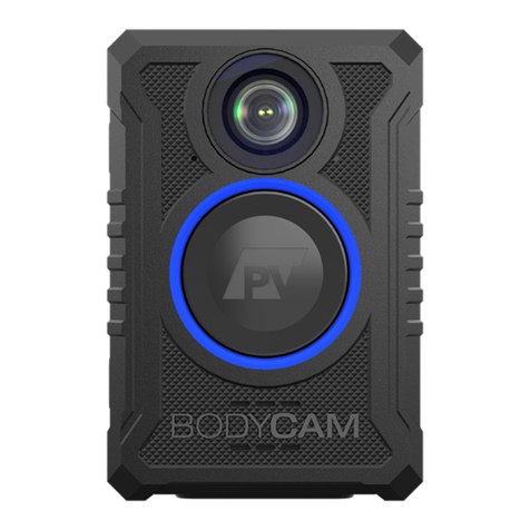
Provision BODYCAM 4 User manual

USER GUIDE
provisionusa.com
01/12/2021
BODYCAM 4

PRO-VISION®
BODYCAM 4 USER GUIDE
provisionusa.com
Thank you for choosing PRO-VISION!
IMPORTANT NOTICES
PRO-VISION tries to ensure that the information provided in this document is as comprehensive as
possible at the time of publication. However, because of PRO-VISION’s drive to provide the best products
through continual improvement, PRO-VISION reserves the right to update the information in this
document at any time without prior notice.
Copyright © 2021 PRO-VISION Solutions, LLC. All Rights Reserved. This document and supporting data
are the exclusive property of PRO-VISION, Inc. and may not be copied, reproduced, or translated to
another language without permission.
PRO-VISION provides no warranty of any kind with regard to this material, including, but not limited to,
the implied warranties of merchantability and fitness for a particular purpose. PRO-VISION shall not be
held liable for errors contained within this document or for incidental or consequential damages in
connection with the furnishing, performance, or use of this material.
SOFTWARE AND FIRMWARE UPDATES
PRO-VISION is committed to the continual testing and improvement of our software and firmware. As
new revisions become available, these updates will be made available to your company; fees may apply
depending on your licensing agreement.
THIRD-PARTY PRODUCTS
PRO-VISION expressly disclaims all responsibility and liability for the installation, use, performance,
maintenance, and support of third-party products. PRO-VISION advised its customers to make
independent evaluations of such products.
SUGGESTIONS
PRO-VISION prides itself on designing its products with the customer in mind. We want to hear from you.
Tell us about your experience and how you are using your PRO-VISION products. Our team is dedicated
to providing the best product experience; we will try our best to accommodate any suggestions provided
into our future products and services.
MANUFACTURER CONTACT INFORMATION
PRO-VISION Solutions, LLC.
8625-B Byron Commerce Dr.
Byron Center, MI 49315
800-576-1126
www.provisionusa.com
For more information about PRO-VISION and its products, go to www.provisionusa.com or call us at
(800) 576-1126.

TABLE OF CONTENTS PRO-VISION®
BODYCAM 4 USER GUIDE
provisionusa.com
Overview...........................................................................................................................................1
Introduction.................................................................................................................................1
Documentation............................................................................................................................1
Camera Familiarization...............................................................................................................2
Setup.................................................................................................................................................3
Docking Station Setup................................................................................................................3
Software Setup...........................................................................................................................8
Camera Configurations...............................................................................................................8
Camera Registration...................................................................................................................9
Camera Mounting...........................................................................................................................10
Rotating Garment Clip..............................................................................................................10
Heavy Duty Magnet Mount.......................................................................................................10
Molle Mount..............................................................................................................................11
Epaulette Mount........................................................................................................................11
Screw-to-fit Mount.....................................................................................................................12
Screw-on Mount........................................................................................................................12
Operation........................................................................................................................................13
User Notifications......................................................................................................................13
Covert Mode.............................................................................................................................15
Mute Function...........................................................................................................................15
GPS Location ...........................................................................................................................16
Video File Names .....................................................................................................................16
Remote Activation .........................................................................................................................17
BODYCAM 4 ............................................................................................................................17
Trigger Device ..........................................................................................................................18
DVR-906LE In-Car System.......................................................................................................19
RFID User Login.............................................................................................................................20
Device Setup............................................................................................................................20
RFID Tag Assignment ..............................................................................................................20
User Login/Logout ....................................................................................................................21
Care and Maintenance...................................................................................................................22
Charging the Battery.................................................................................................................22
Camera Date/Time ...................................................................................................................22
Cleaning the Camera................................................................................................................22
Camera Storage .......................................................................................................................22
Firmware Updates ....................................................................................................................22
Battery Replacement................................................................................................................23
Technical Support..........................................................................................................................25
Warranty.........................................................................................................................................25
Radio Waves ..................................................................................................................................25
Please read this manual carefully before use and keep it for future reference.
Technical support is available Monday thru Friday from 8:00 AM to 5:00 PM EST for questions.

OVERVIEW PRO-VISION®
BODYCAM 4 USER GUIDE
1 provisionusa.com
Overview
Introduction
The BODYCAM 4 camera and its accessories are a system to provide capture of video and audio events
with a battery-powered body-worn device. The camera is mounted to a user using one of the various
mounting options available and records both video and audio. Recording is normally initiated by the user,
but also can be initiated by a remote signal from another camera, vehicle DVR, or independent trigger
device. Recordings are stored securely on internal storage within the device. The user will place the
camera in a single or multi-unit docking station to charge the camera. Videos are transferred through the
docking station’s network connection automatically to the storage location. The transfer process and
storage location are dependent on the agency’s chosen software solution.
1. SecuraMax Cloud Video Management Software
With SecuraMax, the cameras are registered to the SecuraMax website and the cloud server
manages the transfer process, camera configuration, camera user assignments, and video
storage.
2. PV Transfer Software
With PV Transfer, the customer installs an application on their server to handle the management
of the transfer process, camera configuration, and camera user assignments. The server software
is linked to a storage location either on their server directly or their Network Attached Storage
(NAS) device. Video is reviewed through a local storage server or to a SecuraMax server.
The cameras have many configurable settings for recording, but there are four main recording functions
within the camera:
1. Event Recording: A user will manually start and stop Event Recordings using the camera’s front
event button.
2. Pre-Event: When enabled, the camera will begin recording to a buffer whenever it is powered on,
when a user initiates an Event recording with the button, the configured length of buffer before
the button press will be added to the start of the video.
3. Post Event: When enabled, the camera will continue Event Recording for a configured length of
time after the user ends the Event with the camera’s event button.
4. Background Recording: When enabled, the camera will begin recording to a non-event video
location on the camera; this video will eventually fill the camera’s internal storage and begin
overwriting itself. The overwrite process erases the oldest non-event video to make room for
more videos. Background videos are not transferred unless a specific time is requested through
the software.
Other notable recording features:
•In each of the modes above, the camera can be configured to record video only without audio.
•An option can be enabled to allow a user to mute the audio with a button.
•Recording resolution is configurable.
•Recording bit rate is configurable.
•Recording frame rate is configurable.
The camera provides status indicators for the various functions through a front LED, a top LCD display,
audible tones, and vibrations. Each of these indicators has configurable options to allow it to be suited to
the needs of the user.
Documentation
This guide covers the overall setup, configuration, and operation of the BODYCAM 4; other guides are
available to cover additional aspects of the system. All documentation for the BODYCAM 4 product family
is available at www.provisionusa.com/support.

OVERVIEW PRO-VISION®
BODYCAM 4 USER GUIDE
2 provisionusa.com
Camera Familiarization
Function
Action
Power On
Press and hold the Power button
for 3 seconds.
Power Off
Press and hold the Power button
for 3 seconds while the camera is
not recording Events.
Start Event
Recording
Double-press the Event button.
Stop Event
Recording
Press and hold the Event button
for 3 seconds.
Add Marker during
an Event
Single-press the Event button
while Event recording.
Mute or Unmute
Audio Recording
Press and hold F1 button for 3
seconds.
Enter or Exit Covert
Mode
Press and hold the F1 and F2
buttons simultaneously for 3
seconds.
Temporarily
Increase Display
Brightness
Single-press the power button to
increase the display brightness
for 5 seconds.
Recharge and Upload
Display
Cameras are inserted into a single or
multi-unit dock to charge the battery
and upload files.
The cameras will immediately begin
uploading once connected. The
camera’s display will show the upload
status and battery charge status. The
camera’s front LED ring will flash white
during charging and turn solid white
when fully charged.
The display will rotate
automatically from docked to
operational mode; it will
automatically dim after 10
seconds of inactivity.
Event recording initiated by button.
Event recording initiated by signal from another
camera.
Event recording initiated by signal from a car.
Audio is muted or disabled.
Covert mode is enabled (no sounds, vibration, or
front LED).
Battery status.
Battery is charging (when docked).
Pre-Event recording is active.
Background recording is active.
Camera remote activation signal is broadcasting.
Docking Connector
Lens
Display
Mount
F2 Button
Event
Button
Speaker
F1 Button
Microphone
Status LED
Power
Button

SETUP PRO-VISION®
BODYCAM 4 USER GUIDE
3 provisionusa.com
Setup
New BODYCAM 4 cameras must be registered to the software before they can be used. Camera
registration requires that at least one docking station is setup and connected to a network with access to
the server.
Docking Station Setup
There are two different BODYCAM 4 dock offerings: a single bay dock and a 10-bay multi-dock. Both
docking station versions connect to power for charging the camera and Ethernet for offloading video.
Single Unit Docking Station
BC4-DOCK-S
•Secure magnetic camera docking
•Simultaneous charging and transfer
•USB-C Power input
•Direct network uploads, no PC required
•Mounting bracket for wall and vehicle
mounting
•Small Size
10-Unit Multi-Docking Station
BC4-DOCK-10
•10 cameras can charge and transfer
simultaneously
•Secure magnetic camera docking
•Direct network uploads, no PC required
•Secondary network port allows multiple
docks to connect through a single network
connection
•Integrated power supply for improved wire
management
•Wall mounting slots for optional wall
mounting.
Network Requirements & Considerations
The BODYCAM 4 system has very different offloading characteristics compared to previous generation
systems. Previous generations relied upon a USB connection from camera or docking station to a PC; the
BODYCAM 4 does not utilize USB, it can establish a direct network connection from the docking station
to the server.
Considerations:
•Each BODYCAM 4 device requires its own IP address when docked. The dock itself does not
have an IP address, but each bay has its own Media Access Control (MAC) address. The bottom
label of the docking station contains the list of MAC addresses for each bay.
•Dynamic Host Configuration Protocol (DHCP) should be used to provision the IP address and
network configuration for each device. Static IP addresses are not supported, as the devices
could be docked in various locations with different IP configurations. Each BODYCAM 4 docking
bay functions as an ethernet card, with its own MAC address. The multi-dock acts as a network
switch, routing each of the camera ethernet connections through a single connection to the
network. If you are planning to use the dock in a vehicle, additional steps may be required
depending on your in-vehicle setup, see Vehicle Network Configuration on the following page.
•The camera is capable of an upload speed up to 64 Mbps per device if not regulated by network
administrators. There is no Quality-Of-Service (QOS) control on the docking station or camera; it

SETUP PRO-VISION®
BODYCAM 4 USER GUIDE
4 provisionusa.com
is not possible to set upload bandwidth restrictions on the devices. If your agency requires upload
bandwidth-limiting, it is recommended to deploy rate-limiting restrictions in your layer-3
networking infrastructure as needed. Your network switches will have an aggregated view of
devices and traffic; they can allocate all available bandwidth to a single device or small number of
devices when they are the only ones with uploads queued, while limiting the total bandwidth when
large numbers of devices are uploading at once. It is especially recommended to implement a
QOS if the internet connection’s upload speed is low; without QOS, camera uploads could use all
available bandwidth, preventing other services relying on the internet connections to stop
performing correctly.
•The network configuration requires the camera’s network interface to have a direct connection to
the server, use of proxy servers are not supported.
Security Requirements:
The BODYCAM 4 devices and docks are network-connected devices and should only be installed on
networks trusted by the agency in accordance with agency policy. DO NOT expose the BODYCAM 4
devices or docks directly to the Internet. The BODYCAM 4 devices and docks must be connected behind
a firewall or secure network to prevent unauthorized connections being initiated from the Internet or from
clients not trusted by the agency.
You may need some assistance from your IT department to set up the docking stations.
Firewall Configuration:
The BODYCAM 4 devices and docks do not require any incoming data ports for regular operation.
Outbound firewall ports must be opened for proper operation depending on the software used:
•SecuraMax Cloud: Port 443 (TCP) opened for outgoing traffic to your agency’s SecuraMax
Cloud instance. This is used to upload data to SecuraMax using the HTTPS protocol.
•SecuraMax Server: If you are using a self-hosted instance of SecuraMax and will be transferring
files over the Internet from a site that is not on the same LAN as your server, Port 443 (TCP)
must be opened for outgoing traffic to your server’s external address. This is used to upload data
to SecuraMax using the HTTPS protocol.
•PV Transfer: If you are using the PV Transfer software included with the ECB software license to
transfer files over the Internet from a site that is not on the same LAN as your server, Port 5004
(TCP) must be opened for outgoing traffic to your server’s external address. This is used to
upload data to the server using the HTTPS protocol.
Note: 5004 is the default port for PV Transfer and can be changed during software setup.
•Firmware: The cameras check and download firmware from https://firmware.provisionusa.com. If
your device is not updating, ensure that this URL is accessible through the firewall.
•Date/Time: The cameras synchronize time with a NTP time server at https://us.pool.ntp.org. If
your device is not synchronizing time, ensure that this URL is accessible through the firewall.
Vehicle Network Configuration:
To connect a BODYCAM 4 dock in a vehicle, the dock must be connected to an in-vehicle 4G router via
ethernet, or to a laptop with a 4G connection via Ethernet.
In-Vehicle Router:
Connect an Ethernet cable from the Ethernet port of the docking station to an open
Ethernet port on the in-vehicle router. The router will then assign the camera and IP. Test
the setup by docking a configured camera while the router is powered on and connected
and then ensure that the camera gets a network connection.

SETUP PRO-VISION®
BODYCAM 4 USER GUIDE
5 provisionusa.com
Windows Laptop with 4G connection:
Connect an Ethernet cable from the Ethernet port of the docking station to an open Ethernet port on
the in-vehicle laptop. The connection from 4G to the Ethernet will need to be shared within Windows
Internet Connection Sharing (ICS).
1. Open the Windows Network and Sharing Center and choose “Change adapter settings” on the
right.
2. In the Network Connections window, right-click on your 4G Cellular connection and choose
“Properties”.
3. In your devices “Properties” window, choose the “Sharing” tab. In “Internet Connection
Sharing”, check the box next to “Allow other users to connect through this computer’s Internet
Connection” and then choose your “Ethernet” adapter that is connected to the docking station.
4. Click “Ok” to save the sharing properties and begin using Internet Connect Sharing. The dock
should now get an IP address from the laptop; the IP address will be on the default range of
192.168.137.xxx.

SETUP PRO-VISION®
BODYCAM 4 USER GUIDE
6 provisionusa.com
Single Dock Mounting
The single dock can be placed on the desktop or can be mounted directly to a surface or with the
included mounting bracket.
Desktop Placement:
Place the dock directly on the surface with the top arrow facing the user’s position so the camera’s top
display is orientated correctly when docked.
Surface Mounting:
The dock can be directly mounted to a surface such as a vehicle
console or shelf. Locate the dock with the top arrow facing the
user’s position so the camera’s top display is orientated correctly
when docked. There are four screw holes in the bottom of the dock
for mounting; the included mounting bracket can be used as a hole
template for marking and drilling the holes. Use four of the
included mounting screws to mount the dock to the surface.
Bracket Mounting:
The dock can be mounted at a right angle to a mounting surface using the included right-angle mounting
bracket; the bracket can be used in multiple configurations to mount the dock. Locate the dock with the
top arrow facing the user’s position so the camera’s top display is orientated correctly when docked. The
bracket can be mounted with the right angle upward or downward, it can be mounted flush or extended,
and it can be mounted on the side, front, or back.
Single Dock Connections
The single dock can be used for charging only or for both charging and
video offload. For charging-only applications, only the USB-C charging
cable needs to be used and the Ethernet port can be left disconnected.
Power: Connect the included USB-C cable to the USB-C port on the side of the
dock and connect the USB Male connector to the USB wall charging
adapter.
For fastest charging, use only a 2.0A USB charging adapter; smaller
current adapters will take longer to charge the camera.
Network: Connect the included Ethernet cable to the LAN port on the side of the
dock and the opposite end into an active Internet port on your network.
AMPS Mounting Hole Pattern
1.2” 30mm
1.5” 38mm
Side Mounted
Front/Back Mounted
Extended Front/Back
Mounted
Downward
Upward

SETUP PRO-VISION®
BODYCAM 4 USER GUIDE
7 provisionusa.com
Multi-Dock Mounting
The multi-dock is commonly placed on the desktop or flat shelf; its weight and
rubber feet will hold it in place during docking and undocking.
The multi-dock has screw slots on the bottom for attaching to a surface or wall
mounting. The slots are spaced 6” (15 cm) apart left to right and spaced 10.25”
(26 cm) apart front to rear. If mounting the dock vertically, orient it with the
cables exiting the top so the camera’s top display is orientated correctly when
docked.
Multi-Dock Connections
The multi-dock can be used for charging only, or for both charging and video
offload. For charging-only applications, only the power cable needs to be used
and the Ethernet ports can be left disconnected.
Power: Connect the included power cable to the power port on the rear of the
dock and connect the opposite end to a standard power outlet.
Network: Connect the included Ethernet cable to one of the LAN ports on the rear of the dock and the
opposite end into an active Internet port on your network. There are two Ethernet ports on the
rear of the dock; both ports are LAN ports and function the same. After connecting one port to
an active Internet connection, the second port can be used as a pass-through to continue to
another docking station (single or multi), to a PC, or to another network device. This allows
multiple docking stations to be connected to a single available Internet port on the network. It is
important to note that continued chaining of devices will reduce the overall upload speed of the
docks because all the data is passing through the first Ethernet cable. For maximum speed,
connect each dock directly to a Gigabit Ethernet port on your network.
Power
Ethernet

SETUP PRO-VISION®
BODYCAM 4 USER GUIDE
8 provisionusa.com
Software Setup
After a docking station is set up and connected to the network following the instructions in the section
above, software can then be set up and cameras added.
SecuraMax Cloud Software
SecuraMax is set up automatically upon purchase and deployment with PRO-VISION; no further software
setup is required, and cameras can be immediately registered by an administrator. A software
deployment with a PRO-VISION technician is scheduled upon purchase of SecuraMax to configure the
software and explain customization and operation.
PV Transfer Software
PV Transfer software is installed by the customer on a customer-provided server; the location of the
server and its network connectivity is chosen by the customer’s file transfer and storage needs. After
purchase of PV Transfer, an email containing a software license key as well as full setup instructions is
sent to the provided email address.
A copy of the detailed instructions for PV Transfer software setup that is provided via email can be
downloaded from the following link: https://files.provisionusa.com/guides/BC4_PVTransferSetupGuide.pdf
If you did not receive an email containing your license key and instructions after purchase, contact PRO-
VISION technical support via email at support@provisionusa.com. Please include your name, email,
company/agency name and address with your license key request.
Camera Configurations
BODYCAM 4 devices have many configurable options; these options are set centrally on the software
and synchronized to the cameras when they are initially set up and each time they are docked. It is
recommended that the initial camera configuration be set prior to adding cameras so that cameras will be
configured properly as soon as registration is completed.
Configuration Profiles
Configuration profiles are individual profiles that contain unique camera configurations. A “default”
configuration profile is created automatically when the software is set up; additional configuration profiles
are only needed if the company will be assigning different settings for some cameras than other cameras.
For example, it is typical for police departments to have one configuration profile for patrol officers and
another configuration profile for detectives to allow different settings for the different user types.
Modifying a Configuration
1. To modify a configuration, first open a web browser and navigate to your software home page.
2. Next, SecuraMax administrator users locate the “Admin” menu at the top of the page, choose
“Lookups”, then click “BODYCAM 4 Configs”. PV Transfer users will click “Manage BODYCAM
Config Profiles” at the top of the page.
3. If you are using a single configuration for all cameras, it is easiest to just modify the “default”
configuration by clicking “Edit” to the right of the “default” title.
4. Modify the configuration as desired. If you are unsure of a settings function, leave it at the default
value or read through the remainder of the guide to understand its function before modifying it.
The most important option that should be set is the time zone; please ensure this is properly set
as improper configuration could make it difficult to locate video if the camera’s time zone is not
set correctly during recording.
5. After the configurable options are set to the desired values, click “Save” at the bottom of the
page.
Assigning a Configuration
If you are using SecuraMax and are using more than one configuration, you will need to assign the
individual configuration profiles to each user group by clicking the “Assign to Groups” tab at the top of the
“BODYCAM 4 Configs” page.

SETUP PRO-VISION®
BODYCAM 4 USER GUIDE
9 provisionusa.com
Camera Registration
After software setup has been completed, new cameras can be added.
SecuraMax Cloud Software
A software deployment with a PRO-VISION technician is scheduled upon purchase of SecuraMax. During
the deployment process the PRO-VISION technician will walk the administrator through the camera
registration process for the first few cameras.
After deployment, new devices can be easily added:
1. Open a web browser and log in to your SecuraMax administrator account.
2. From any SecuraMax web page, go to the “Admin” menu and the choose “Devices.”
3. Click on the “Add BODYCAM 4 Device” from the left side menu of the “Devices” page.
4. Instructions for adding a new camera are provided on the page:
a. Remove the new BODYCAM 4 camera from its packaging and then
power it on by pressing and holding the power button for 3 seconds.
New / Unregistered cameras will display “NOT SETUP” on the top
LCD once powered on.
b. Hold the camera with the lens facing toward the QR codes displayed
on the screen at about 6-8” away and then press the “F1” button on
the side.
c. The camera will scan the QR code on the screen and then display
“SUCCESS” followed by “QR SAVED”.
d. Place the camera in the docking station; the camera will chirp to note that it was docked,
and the display will change to “NOT ASSIGNED”.
e. After a few moments, the camera serial number will appear in the “Step 3” section of the
web page, the camera user mode can be selected and for single user mode cameras, the
user can be assigned. For additional details on the “User Mode” options, see the RFID
User Login section of this guide.
f. Press “Finish and Assign” to complete registration.
PV Transfer Software
Customers that followed the setup guide provided with the PV Transfer software have already registered
new cameras following the registration instructions in the guide.
After initial setup, new devices can be easily added at any time:
1. Open a web browser on the server computer and navigate to the software web interface (typically
https://localhost:5004).
2. From the top menu, click on “Add BODYCAM” to navigate to the “Add a BODYCAM 4” page.
3. Instructions for adding a new camera are provided on the page:
a. Remove the new BODYCAM 4 camera from its packaging and then
power it on by pressing and holding the power button for 3 seconds.
New / Unregistered cameras will display “NOT SETUP” on the top
LCD once powered on.
b. Hold the camera with the lens facing toward the QR codes displayed
on the screen at about 6-8” away and then press the “F1” button on
the side.
c. The camera will scan the QR code on the screen and then display
“SUCCESS” followed by “QR SAVED”.
d. Place the camera in the docking station; the camera will chirp to note that it was docked,
and the display will change to “NOT ASSIGNED”.
e. After a few moments, the camera serial number will appear in the “Step 3” section of the
web page. Enter the desired name for the camera (Typically the name of the user the
camera will be assigned). Pay attention to formatting of the camera name as it will be
displayed on the camera’s display and in every video filename from the camera.
f. Press “Finish and Assign” to complete registration.

CAMERA MOUNTING PRO-VISION®
BODYCAM 4 USER GUIDE
10 provisionusa.com
Camera Mounting
The BODYCAM 4 has multiple mounting options available for purchase; all mounts attach to the rear of
the camera on the sliding rail.
Rotating Garment Clip
The rotating garment clip (P/N: BC4-MNT-GAR) is a simple mounting method that
attaches to a garment with a spring-loaded plastic clip. The clip can rotate 360°to
allow it to attach to the garment at different angles. The inner portion of the clip has
interlocking teeth to provide grip onto the attachment point of the garment.
Mounting:
To install the mount onto the camera, simply slide the mount upward into the slot on the
rear of the camera until it clicks into place. The mount can be left attached to the camera in
the docking station.
Removal:
To remove the mount, rotate the clip so it is perpendicular to the camera body; this
provides access to the retention tab. Hold the camera with one hand and the clip with the
other. Push the retention tab on the clip away from the camera body while simultaneously
sliding the clip down and out of the camera slot.
Heavy-Duty Magnet Mount
The magnet mount (P/N: BC4-MNT-MAG) consists of two parts: the inner mount,
and the outer mount. The inner mount is placed behind the garment and the outer
mount is placed on the outside of garment holding the mount in place with strong
magnets.
Mounting:
1. Slide the camera down onto the outer mount until it clicks in
place.
2. Place the inner mount behind the garment in the desired
mounting area.
3. Hold camera with attached outer mount over the garment in
front of the inner mount and they will attach magnetically.
Removal:
1. Firmly grasp the side rails of the outer mount and tip assembly right
or left to separate the mount, then pull the outer mount away to
remove.
2. Remove the inner mount from behind the garment.
Storage:
It is best to store the mounts with only two of the magnets on each portion connected
for easy separation.
Safety Information:
Individuals with pacemakers or internal medical devices should use caution when handling the
BODYCAM 4 magnetic mount. Magnetic fields may affect the operation of these devices. Consult with
your physician and the manufacturer of your medical device to determine its susceptibility to static
magnetic fields before handling the magnetic mount. Individuals with pacemakers and other internal
medical devices that could potentially be affected by static magnetic fields should not wear the magnetic
mount.
The BODYCAM 4 Magnetic Mount contains strong magnets and can pose a pinch-point hazard. Exercise
caution when separating and connecting the outer and inner magnetic mount. When connecting the two
pieces, ensure that all body parts are clear as the magnets will snap together.

CAMERA MOUNTING PRO-VISION®
BODYCAM 4 USER GUIDE
11 provisionusa.com
Molle Mount
The Molle mount (P/N: BC4-MNT-MOL) is designed to attach to Molle vests and jackets.
The mount consists of an adapter that mounts to the rear of the camera and the Molle
mount that is attached to the Molle vest or jacket. The mount can be left attached to the
vest or jacket while the camera is removed for charging and upload. To attach the
camera, slide it down into the mount until it clicks. To remove the camera, rotate it 180°
and slide upward to remove as shown below at right.
Epaulette Mount
The epaulette mount (P/N: BC4-MNT-EPL) is designed to attach to the epaulette on the
shoulder of a uniform. This mount can only effectively be used if the uniform has
epaulettes. The mount consists of an adapter that mounts to the rear of the camera and
the mounting portion that is attached to the garment’s epaulette. The mount can be left
attached to the vest or jacket while the camera is removed for charging and upload. To
attach the camera, slide it down into the mount until it clicks. To remove the camera,
rotate it 180°and slide upward to remove as shown below at right.

CAMERA MOUNTING PRO-VISION®
BODYCAM 4 USER GUIDE
12 provisionusa.com
Screw-to-fit Mount
The screw-to-fit mount (P/N: BC4-MNT-STF) is a durable mount that is intended for use
in applications where a garment is too thick for a magnet mount, and/or does not have
provisions for attaching a clip. Typically, this mount is used in applications where heavy
coats or outer vests are worn. The mount is semi-permanently attached to the garment
using a backing plate and screws. The mount is machine washable so it can stay
attached to the clothing indefinitely. Using this mount will leave 4 small holes in the
garment and may deform the shape of the garment surface over time. The mount
consists of an adapter that mounts to the rear of the camera and the mounting portion
that is attached to the garment’s epaulette. The mount can be left attached to the vest or
jacket while the camera is removed for charging and upload. To attach the camera, slide it down into the
mount until it clicks. To remove the camera, rotate it 180°and slide upward to remove as shown below at
right.
Screw-on Mount
The screw-on mount (P/N: BC4-MNT-SCO) is intended to be used in applications where
the camera will be mounted to a fixed bracket, wall, or other non-user mounted
application. Attach the mount to the surface using four (4) suitable mounting screws for
the desired surface. Attach the mount to the rear of the camera as shown below left. To
attach the camera, slide it down into the mount until it clicks. To remove the camera,
rotate it 180°and slide upward to remove as shown below at right.

OPERATION PRO-VISION®
BODYCAM 4 USER GUIDE
13 provisionusa.com
Operation
The BODYCAM 4 was designed to provide simple intuitive user operation and easy observation of the
camera’s status with its integrated top LCD display. The operational functions of the camera may vary
slightly depending on the chosen configuration set in the software. If it does not appear that a function is
working as expected, review the guide for the feature and then ensure that it is properly set or enabled
within the camera’s configuration on the server.
Note: If changes to the camera’s configuration are made after the camera is initially set up, it must then
be docked to have the updated configuration synchronized to the camera.
In a typical daily operation, at the beginning of the shift, the camera user would locate their camera in the
docking station by observing the user’s name on the top LCD screen. If the display says “READY”, then
the camera has finished uploading and is ready for use. If the battery icon is full or the front LED is solid
white, then the battery is fully charged. Remove the camera from the docking station and it will chirp to
indicate it has changed state to undocked. If the camera was set to pre-event or background record, the
blue LED ring will illuminate light blue and a “P” and/or “B” icon will appear in the upper left corner of the
display to indicate the pre-event and/or background recording status. The camera is ready for use.
User Notifications
The camera provides status notifications to the user for operation visually through its top LCD display and
front LED ring, audibly through its speaker, and physically through a vibration motor.
Action
Display
Sound
Vibration
Status LED Ring
Power On
None
None
Off
Power Off
None
Short Pulse
Off
Not ready, no user (RFID
Login only)
3 Short Tones
3 Pulses Every 30s
Off
Ready to Event Record
None
None
Off
Ready to Event Record
while Pre-Recording and
Background Recording
None
None
Light Blue
Event Recording Started
by Event Button
Short Chirp Up
Short Pulse
Bright Blue
Event Recording Started
by Another BODYCAM
Short Chirp Up
Short Pulse
Bright Blue
Event Recording Started
by Signal from a Camera
Short Chirp Up
Short Pulse
Bright Blue
Event Recording Stopped
Short Chirp Down
Long Pulse
Return to READY
Audio Muted
None
None
No Change
Audio Unmuted
None
None
No Change
Enter Covert Mode
None
None
Off
Exit Covert Mode
None
None
Return to Normal
Low Battery >10%
Battery Remaining
Double Chime
Short Pulse
No Change
Low Storage <15%
Space Remaining
Double Chime
Short Pulse
No Change
Storage Full, Cannot
Continue Recording
Double Chime
Short Pulse
Off

OPERATION PRO-VISION®
BODYCAM 4 USER GUIDE
14 provisionusa.com
Front LED
The BODYCAM 4 has a LED ring around the front Event button. This LED functions to show the
recording state when in use, and the charging state when docked.
Light Blue
Bright Blue
White
Solid –Pre-Event Recording
Solid –Event Recording
Pulsing –Event Recording with
Audio Disabled or Muted
Solid - Charged
Pulsing - Charging
The front LED can be disabled completely as an option in the camera settings. The front LED can also be
disabled temporarily by using Covert Mode.
Audible Tones
The camera provides audible tones during operation for event recording started, event recording stopped,
every 5 minutes during recording, low battery, and low storage space.
The audible tones can be disabled completely as an option in the camera settings. The audible tones can
also be disabled temporarily by using Covert Mode.
Vibrations
The camera provides haptic feedback through vibrations to indicate various functions including power on,
power off, low battery, event recording started, event recording stopped, and low storage space.
The camera vibrations can be disabled completely as an option in the camera settings. The camera
vibrations can also be disabled temporarily by using Covert Mode.
Display
The camera has a full color LCD display on top that indicates important information to the user. The
display will rotate automatically from docked to operational mode. The display will automatically dim after
30 seconds of inactivity. A single press of the power button will temporarily increase the display
brightness for 30 seconds.
Docked Mode
Operational Mode

OPERATION PRO-VISION®
BODYCAM 4 USER GUIDE
15 provisionusa.com
Docked Mode
Operational Mode
Battery is charging
Battery charge level
Connecting to server
Uploading files to server
File upload / sync complete
Server / upload error
Firmware update check
Firmware update downloading
Firmware update check error
Firmware up to date
Event recording initiated by button
Event recording initiated by signal from
another camera
Event recording initiated by signal from a
vehicle DVR or trigger device
Audio is muted or disabled
Covert mode is enabled (no sounds,
vibrations, or LED)
Battery charge level
Pre-Event recording is active
Background recording is active
Camera remote activation signal is
broadcasting
Covert Mode
In certain situations, it may be desired to temporarily disable the
notifications on the BODYCAM 4. Covert mode is a feature that disables the
audible tones, vibrations, and front LED.
•To enable Covert mode, press the F1 and F2 buttons
simultaneously for 3 seconds. A covert mode icon will appear on
the right side of the display when covert mode is enabled.
•To disable, press and hold the F1 and F2 buttons simultaneously for 3 seconds; the icon will
disappear from the screen and the audible tones, vibrations, and front LED will returned to their
previous functions.
Note: When the camera is powered off, the camera will automatically disable covert mode.
Mute Function
Some organizations require the user to be able to temporarily mute the
audio to meet the specific needs of the environment, location, or laws. The
camera has a function to mute audio by pressing and holding the F1 button
for 3 seconds while the camera is powered on. When audio is muted a mute
icon will appear on the center right side of the display. To unmute the
audio, press and hold the F1 button for 3 seconds.

OPERATION PRO-VISION®
BODYCAM 4 USER GUIDE
16 provisionusa.com
GPS Location
The BODYCAM 4 has a built-in GPS module that provides location information to accompany the video.
The GPS signal status can be observed on the camera’s display; it is pin icon that appear next to the
battery. When the icon is red it is acquiring a signal; when the icon is white it has a good signal. The GPS
signal may be poor when indoors or in terrain where the antenna cannot get a good signal.
When the GPS has a good signal, location information is stored in the video on both the on-screen
display and in the video metadata.
GPS Sigal Acquired GPS No Signal / Acquiring
Video On-Screen Display (OSD)
The coordinates can be entered into mapping software to provide exact location.
Video File Names
The BODYCAM 4 creates video files during recording that include details about the file in its name. The
files are named and stored in a folder structure based on the start time of the video.
Example Video File Name:
1_20201210-08214036_1130s5_2010B406088_john.smith.mp4
1_{Year}{Month}{Day}-{Hour}{Minute}{Second}{Millisecond}_{Video Format}_{Serial}_[User Name].mp4
1 Camera number; For the BODYCAM 4 this is always “1”
20201210 Date when the video was started
08214036 Time when the video was started, Hour, Minute, Second, and Millisecond
1130s5 Video format used by software for playback
2010B406088 Camera’s serial number
john.smith Camera’s logged-in username

REMOTE ACTIVATION PRO-VISION®
BODYCAM 4 USER GUIDE
17 provisionusa.com
Remote Activation
The BODYCAM 4 has a radio that can transmit and receive a signal that can be used to remotely start
recording. The camera must first be configured to use the remote activation function.
Configurable options:
1. Allow camera to be activated by other BODYCAM 4 cameras? Y/N
2. Allow camera to be activated by a PRO-VISION In-Car System (P/N: DVR-906LE)? Y/N
3. Allow camera to be activated by a PRO-VISION Trigger Device (P/N: BC4-TRIGGER)? Y/N
4. Activate camera from devices? My Organization / All Compatible
5. Allow camera to activate other cameras? Y/N
When properly configured, if a user activates Event recording on a BODYCAM 4 device by double-
pressing the front Event button, any cameras that are powered on and ready to record within a 30 ft. (9M)
range of the camera will begin Event recording automatically.
•When a device is activated by the remote signal, recording notifications will occur as if the user
has activated it manually, but the LCD display will show an indicator of the type of device that
activated it.
•When a device is manually activated by the Event button, it will continue broadcasting a signal for
other devices to start Event recording until it is manually stopped by pressing and holding the
Event button for 3 seconds.
•Devices that are activated by the remote activation signal do not also broadcast a signal.
•Remote activation only starts Event recording; Event recording must be stopped individually on
each device that was activated.
BODYCAM 4
The BODYCAM 4 can broadcast a signal when it is Event recording so other BODYCAM 4 units will
automatically activate when in proximity of the active camera.
When configured properly, the camera that was manually activated
with the button will display a beacon icon in the top bar of the LCD
and a manually activated icon to the left of the recording time.
(Show at right)
The camera(s) that were activated by the signal from the other
BODYCAM 4 will display an icon representing activation by another
BODYCAM 4 to the left of the recording time. When the camera is
activated it will follow the same sounds, LED states, and vibrations as when
the camera is manually activated by the user.
Configuration:
For two BODYCAM 4 devices to activate each other, the activating BODYCAM must be configured so
that “This camera can activate other cameras” is enabled. The camera(s) that will be activated must be
configured so that “Camera can be activated by other BODYCAM 4 cameras” is enabled.
General Information:
•When a camera is activated by a signal, it must manually be stopped by using the camera’s
Event button. The signal does not stop the recordings.
•Cameras that are activated by a signal do not broadcast a signal themselves. Only cameras in
the proximity of the signal originator will be activated.
•When an event is manually started, the signal is broadcast until the event on that camera is
manually ended. If another configured BODYCAM 4 enters the proximity of that camera at any
time during the Event, it will be activated.
•Once a camera has been remotely activated by a signal, if that remotely activated camera
manually ends the event, it will not become reactivated by that same signal.
Other manuals for BODYCAM 4
2
This manual suits for next models
2
Table of contents
Other Provision Digital Camera manuals

