PSA ELA Manual

Einbau-, Betriebs- und Wartungsanleitung
Installation, Operation and Maintenance Instructions
PSA ELA®/ PSA ELA®K
Rückflusssperre / Non Return Valve
© Copyright 02/2012 PSA Wasserarmaturen GmbH
PSA
PSA Wa sse ra rma ture n
Einbau-, Betriebs- und Wartungsinstruktionen
Installation, Operation and Maintenance Instructions
Bitte lesen Sie in jedem Fall unser „Allgemeine Einbau-, Betriebs-
und Wartungsanleitung – Armaturen –„
Die Einbaulage ist horizontal bis vertikal ( Durchströmung von unten nach
oben ).
Der Einbau muss von einem Fachmann durchgeführt werden. Lokale,
regionale sowie andere spezifische Einbauvorschriften sind unbedingt zu
beachten. Es ist auf richtige Durchströmung zu achten
Der Einbau muss mit geeigneten Hebezeugen sowie mit Hanfstricken, die
eine Beschädigung der Beschichtung verhindern, erfolgen
Grundsätzlich muss die PSA ELAmind. 3 bis 4 x DN von allen Einbauten
entfernt installiert werden. Kürzere Einbauabstände können infolge
auftretender Turbulenzen, zum frühzeitigen Verschleiß der Klappenscheibe
führen
Die PSA ELAmuss kräfte- und momentenfrei zwischen die dafür
vorgesehenen Rohrleitungsflansche eingebaut werden
Die PSA ELAdarf nur innerhalb ihrer angegebenen Temperaturgrenzen
betrieben werden. Die PSA ELAdarf nur für die vorgesehenen Medien
eingesetzt werden. Beim Einsatz in anderen Medien verliert die
Gewährleistung ihre Gültigkeit bzw. der Einsatz in andere Medien muss
vorher von uns geprüft und schriftlich bestätigt sein
Die PSA ELAunterliegt grundsätzliche keiner kontinuierlichen Wartung.
Die Klappenscheibe ist jedoch ein Verschleißteil und muss, je nach
Betriebsbedingungen, von Zeit zu Zeit ausgetauscht werden. TIPP: Die
Klappenscheibe der PSA ELAkann beidseitig verwendet werden.
ACHTUNG ! Die PSA ELAmuss vor dem Öffnen drucklos sein. Das
Wartungspersonal muss sicherstellen, dass die PSA ELAin drucklosem
Zustand ist.
Nach dem Öffnen des Gehäuses z.B. zum Wechsel der Klappenscheibe,
muss der Deckel O-Ring erneuert werden. Der O-Ring ist z.B. im Ersatzteil
Set 1 der Klappenscheibe enthalten. Wird das Gehäuse andererseits
geöffnet muss ein neuer O-Ring von uns angefordert werden.
Wir empfehlen NICHT Ersatz-Klappenscheiben vorrätig zu halten, da sie
im Laufe der Zeit altern und ihre Elastizität verlieren. Ersatz-
Klappenscheiben sind in allen Größen, immer (Zwischenverkauf
vorbehalten) bei uns vorrätig. Wenn Klappenscheiben gelagert werden,
sind sie gegen ultraviolettes Licht zu schützen.
Gemäß Druckverlustdiagramm (siehe Internet unter http://www.psa-
wasserarmaturen.de) sollte eine PSA ELA Rückflusssperre mit nicht
weniger als 0,5 bar betrieben werden. Ist der Betriebsdruck kleiner 0,5 bar
muss dies bei Auftragserteilung bekannt gegeben werden, damit
eventuelle Maßnahmen getroffen werden, um eine Undichtheit am Deckel
zu vermeiden.
In any case, please read our “General Installation,
Operation and Maintenance Instructions – Valves”
The installation orientation is horizontal to vertical ( flow
upwards ).
The installation must be executed by skilled personal, only.
Local, regional as well as any specific regulation must be
regarded. The correct flow direction must be observed
The installation must be executed with proper lifting devices
as well as hemp ropes in order to avoid damage to the
coating
In principle the PSA ELAmust be installed min. 3 – 4 x DN
from any device. Shorter distances can cause premature
wearing to the flap, due to turbulences
The PSA ELAmust be installed between the pipe flanges
free of any forces or moments
The PSA ELAmay only be operated within its temperature
limits. The PSA ELAmay only be operated for the allowed
fluids. If operated with other fluids the warrantee is void, resp.
it must be approved by us and confirmed in writing
The PSA ELAdoes not require continues maintenance.
However, the flap is a wearing part and must be, based on
the operating conditions, changed from time to time. HINT:
The flap of the PSA ELAcan be used on both sides.
CAUTION ! The maintenance may only be executed on the
pressureless PSA-RSK. The maintenance personell must
make sure that the PSA-ELAis in a pressureless state.
After the body was opened e.g. to change the flap, the
bonnet o-ring must be renewed. This o-ring is included in the
spare part set 1 of the spare flap. If the body was opened
otherwise a new o-ring must be purchased from us.
We do NOT recommend to stock flaps, since they age and
loose their elasticity. Spare diaphragms are, in all sizes,
always on our stock (intermediate sales reserved). If flaps
are stocked, they must be protected against ultra violet light.
According our pressure loss diagram (see on the internet
under http://www.psa-wasserarmaturen.de) the PSA ELA
non-return valve may not be operated below a operating
pressure of 0,5 bar. If the operating pressure is below 0,5 bar
this must be mentioned on in your purchase order so we can
take measure to avoid eventual leaking on the bonnet.
Einbau waagrecht
Installation horizontal Einbau senkrecht
Installation vertical
Einbau waagrecht
Installation horizontal Einbau senkrecht
Installation vertical

Technische Änderungen jederzeit vorbehalten
Subject to change without prior notice
PSA
PSA Wa sse ra rma ture n
Einbau-, Betriebs- und Wartungsinstruktionen
Installation, Operation and Maintenance Instructions
1
2
Austausch Klappenscheibe PSA ELA Typ „K“
Changing of flap on PSA ELA Type „K“
Wechsel (Drehen) der Klappenscheibe
Die Armatur muss drucklos sein
Deckelschrauben lösen
Klappenscheibe herausnehmen (und drehen)
Klappenscheibe wieder einsetzen und Deckel aufsetzen. Es wird
empfohlen die Deckeldichtung zu erneuern
Deckelschrauben wieder gleichmäßig, im Wechsel, anziehen.
DN 40 - 50 = 45 Nm
DN 65 - 100 = 110 Nm
DN 125 - 300 = 160 Nm
Changing (Turning) of the Flap
The valve must be pressureless
Loosen the bonnet bolts
Take out the flap (and turn it)
Insert the flap again and put the bonnet back on. It is
recommended to replace the bonnet gasket
Put the bonnet bolts back in and fasten them, alternately
DN 40 - 50 = 45 Nm
DN 65 - 100 = 110 Nm
DN 125 -
300 = 160 Nm
Zum Tausch der Klappenscheibe an der PSA ELA Typ „K“ gehen
Sie wie folgt vor:
Die Klappenscheibe wird von zwei Stiften gehalten; Stift 1 und Stift 2. Wie
oben gezeigt. Diese Stifte sind unterschiedlich lang. Stift eins sitzt im
Gehäuse auf, während Stift 2 etwas Raum zum Gehäuse hat
Um die Klappenscheibe zu tauschen ist es notwendig Stift 2 mittels eines
starken Schraubendrehers oder eines sonst geeigneten Werkzeuges
anzuheben
Dazu gehen Sie mit dem Werkzeug unter den Stift und drücken diesen
soweit hoch bis er nicht mehr ins Gehäuse steht
Nun können Sie die Klappenscheibe heraus drehen in dem Sie sie etwas
hochbiegen und nach unten drehen
Die neue Klappenscheibe wird nun gerade umgekehrt in das Gehäuse
eingesetzt. Dazu biegen Sie die Klappenscheibe etwas hoch, setzen das
frei Ende am oberen Zapfen hinter Stift 1 und drehen Sie die
Klappenscheibe komplett ins Gehäuse. Sie muss nun auf dem Sitz
aufliegen
Nun wird Stift 2 mit einem Hammer wieder ins Gehäuse eingeschlagen,
jedoch nur soweit bis er mit der Gehäuse Oberfläche bündige ist.
Unter keinen Umständen Stift 2 soweit einschlagen bis er im Gehäuse auf
dem Boden aufsitzt. Die Klappenscheibe wäre danach nicht mehr
demontierbar Drehen der Klappenscheibe
ACHTUNG ! Die Klappenscheibe kann beidseitig verwendet werden
Um die Klappenscheibe zu drehen, gehen Sie wie vor beschrieben vor, nur
dass Sie die Klappenscheibe drehen und danach wieder einsetzen und
keine neue Klappenscheibe verwenden
To change the flap on the PSA ELA Type “K” operate as
follows:
The flap is kept in place by two pins; pin 1 and pin two as
shown above. These pins have different length. Pin 1 is
touching the bottom of the body while pin 2 has a little room
to the bottom of the body
In order to change the flap it is necessary to lift pin 2 with a
screw driver or another suitable tool
To do this go under pin 2 and press it up until it is no longer
reaching in the body
Now you can take out the flap by bending it up some what
and turn it downward
To install the new flap just operate backwards. Bend the flap
slightly, put the free end on top behind pin 1 and turn the flap
inward in the body. The flap is sitting on the seal area
Now you push pin 2 into the body again by using a hammer
but only that far until the pin is evem on the outside of the
body
Do, under no circumstances push pin 2 all the way into the
body until it sits at the bottom. The flap could not be
disassembled anymore
Turning of the Flap
CAUTION ! The flap can be used on both sides
In order to turn the flap, operate the same way as written
before except that the flap is turned and put back into the
body and not a new flap is used
This manual suits for next models
1
Other PSA Control Unit manuals
Popular Control Unit manuals by other brands
ITT
ITT Engineered Valves CU27 Installation, operation and maintenance manual

GF
GF Signet 9950 instruction sheet

Nuvoton
Nuvoton TOF KHKT001 Hardware guide
Idex
Idex WARREN RUPP SANDPIPER Signature Series Service & operating manual
Chandler Systems
Chandler Systems DROP CS125 Series manual
Mircom
Mircom QDV-1000 manual

Lefroy Brooks
Lefroy Brooks M1-2675 Installation, operating, & maintenance instructions

Alinx
Alinx AC7Z100B user manual
Emerson
Emerson Fisher V250 instruction manual
Broan
Broan VAUTOW Installation and user guide
resideo
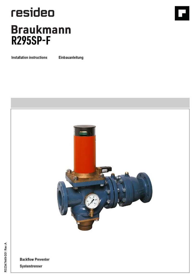
resideo Braukmann R295SP-F installation instructions
Harman
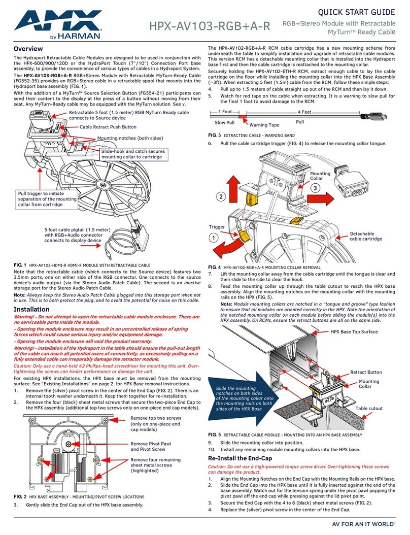
Harman AMX HPX-AV103-RGB+A-R quick start guide
