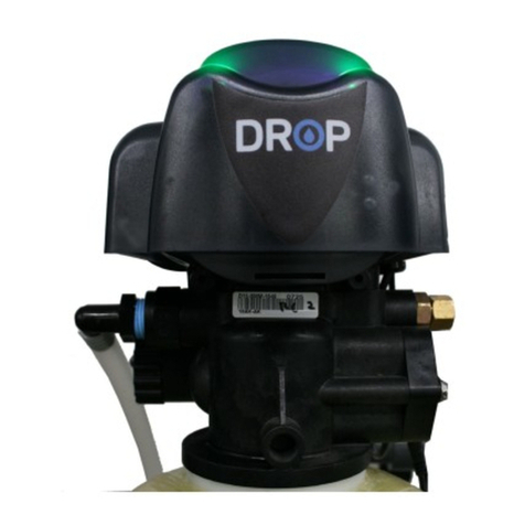
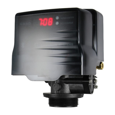
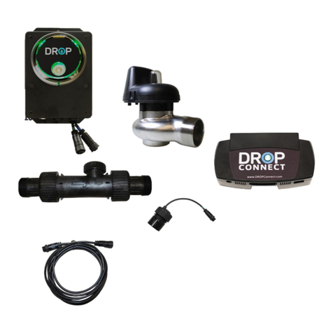
Chandler Systems DROP CS125 Series User manual

Chandler Systems
Commercial
Control Valve Manual
CS125 & CS150 Series

2
INTRODUCTION
Thank You for Purchasing a DROP System
We know you’ll love your improved water quality, leak detection ability and water conservation benefits of
your new DROP Water Management System from Chandler Systems. You’ll soon wonder how you ever
lived without it. Improving your water and protecting your home are just a few of the ways that the DROP
Water Management System can improve your water system.
Be sure to check out the dropconnect.com website periodically for more information about additional DROP
products as they are released.
888.363.9434 dropconnect.com
To further help you operate your new DROP system, we have provided you with many other resources for
you to learn more. Feel free to call Chandler Systems when you need additional help. We also have many
resources located on our website including instructional videos, and images.
DROP Connect is also active on various social media pages! Feel free to follow us for the most up to date
information and news!
@dropconnect
FCC Compliance Statement:
https://dropconnect.com/sites/default/files/FCC_Compliance_Statement.pdf
Industry Canada Compliance Statement:
https://dropconnect.com/sites/default/files/Industry_Canada_Compliance_Statement.pdf
Privacy Statement
For more information about privacy, visit our privacy policy online.
(https://dropconnect.com/sites/default/files/DROP-Privacy-Statement.pdf) online.
DROP Patents
For the most up-to-date list of patents, visit our patents on our website: https://dropconnect.com/patents.

3
TABLE OF CONTENTS
Introduction................................................................................................................ 2
Table of Contents....................................................................................................... 3
DROP Valves............................................................................................................ 4
Operations................................................................................................................. 5
Valve Description............................................................................................. 6
Valve Operation............................................................................................... 7
Lights - Regeneration....................................................................................... 8
Advanced Configuration................................................................................... 9
Quick Reference Table.................................................................................... 11
Injectors........................................................................................................... 12
Connections..................................................................................................... 13
CS125 Valve Breakdown............................................................................................ 14
CS125 Brine Connection............................................................................................ 15
CS125 Injector Assy................................................................................................... 16
CS150 Valve Breakdown............................................................................................ 17
CS150 Drain Connection............................................................................................ 18
CS150 Brine Connection............................................................................................. 19
CS150 Injection Assy................................................................................................. 20
CS125 & CS150 Powerhead...................................................................................... 21
Valve Body Flow Diagrams........................................................................................ 22
DROP Warranty......................................................................................................... 28

4
DROP VALVES
DROP CS150 Commercial Softener Valve
DROP CS125 Commercial Filter Valve

5
OPERATIONS
DROP Models
Model Number Description Piston Type Injector / Plugs Valve Body
20125X500
Softener Valve,
Rear Inlet/Outlet, for
Single Tank
Operation with
Manual Bypass
Hard water
bypass during
regeneration with
integrated water
shutoff
Injector CS125
20125X600
Filter Valve, Rear
Inlet/Outlet, for
Single Tank
Operation with
Manual Bypass
Hard water
bypass during
regeneration with
integrated water
shutoff
Plugs in Injector
Port and Refill
Port
CS125
20125X550
Softener Valve,
Rear Inlet/Outlet, for
Multi-Tank
Operation with
Manual Bypass
No Hard water
bypass during
regeneration with
integrated water
shutoff
Injector CS125
20125X650
Filter Valve, Rear
Inlet/Outlet, for
Single Tank
Operation with
Manual Bypass
No Hard water
bypass during
regeneration with
integrated water
shutoff
Plugs in Injector
Port and Refill
Port
CS125
20150X500
Softener Valve, Side
Inlet/Outlet, for
Single Tank
Operation
Hard water
bypass during
regeneration with
integrated water
shutoff
Injector CS150
20150X600
Filter Valve, Side
Inlet/Outlet, for
Single Tank
Operation
Hard water
bypass during
regeneration with
integrated water
shutoff
Plugs in Injector
Port and Refill
Port
CS150
20150X550
Softener Valve,
Side Inlet/Outlet, for
Multi-Tank
Operation
No Hard water
bypass during
regeneration with
integrated water
shutoff
Injector CS150
20150X650
Filter Valve, Side
Inlet/Outlet, for
Single Tank
Operation
No Hard water
bypass during
regeneration
with integrated
water shutoff
Plugs in Injector
Port and Refill
Port
CS150

6
OPERATIONS
Detailed Valve Description
The DROP 1.25” and 1.5” valves are fully automatic control mechanisms to direct and regulate all cycles
of the water treatment unit. The control valve has been designed to make it easily serviceable. The inlet,
outlet, drain and access to the water meter are all hand only tighten nuts making them quick and conve-
nient to service. Accessing the injector or the brine port plug is quick access plug-in style with a clip, pos-
sibly only needing a flat head screwdriver to open the plug. Accessing the piston and seals only requires
removing 5 Philips head screws and separating a few plastic clips by hand. All of this means that the
valve is quick and simple to service and you do not need any specialized tools to work on the valve.
The control valve has two piston options. The first is a hardwater bypass piston, which allows hard water
to be bypassed from inlet to outlet during the valve regeneration cycle. This is typical on a single tank
softening system. The other option is a non-hardwater bypass piston option, which does not bypass
hardwater from the inlet to the outlet during the valve regeneration cycle. All pistons have a patented
water shutoff position (U.S. Patents 9714715 & 10012319), which can be used by a DROP system to
protect properties from the risk of water damage from leaks and water breaks. When combined with the
non-hardwater bypass piston type, this feature allows the commercial DROP valves to be used in paral-
lel without the need of external shut-off valves. When used in this way, the DROP system can provide
continuous treatment of water. The DROP hub can command valves to be in service, providing treated
water, or in stand-by with outlet water shut off waiting for when it is needed. During the regeneration
process, inlet water is used to perform the steps of the regeneration of the softener tank and the outlet
water port is shut off. For more detailed information about multiplexing DROP valves, see our “Multiplex-
ing Filters and Softeners” Application Manual. The control valves / pistons are only available in downflow
regeneration.
The DROP valves include a turbine flow meter that is integral to the valve body. The meter is quick to
access without having to separate any plumbing in case of needing to service the meter. Simply turn
the bypass valve to bypass or turn the water off in the DROP App and loosen the nut securing the water
meter, if necessary, use a flathead screwdriver under the edge to remove the flow meter from the outlet
port of the valve. The meter is calibrated in Chandler Systems lab and has excellent accuracy at all flows
above 0.75 gallons per minute. The meter allows the DROP system to properly protect a property and to
notify the end user of usage and potential problems.
There is also a combination turbine flow meter and pressure sensor that is optionally available. The com-
bination meter can directly replace the standard flow meter as it plugs directly into the same wire connec-
tion. Once installed, the DROP system can then monitor the system water pressure at the outlet of the
valve. The water pressure can then also be viewed by the user in the DROP App.
Combining these control valves with a DROP control system creates a water treatment system that is the
easiest in the industry to install, setup and maintain. The DROP system gives the end user easy control,
information, and history of the water treatment system. DROP is a unique water management system.
Using the DROP Hub, DROP monitors water usage and manages the water-related devices throughout
the entire installation. DROP can operate locally without an internet connection or has the added ability to
send mobile alerts when connected to a WiFi network. This advanced system can allow remote monitor-
ing and adjustments—all from your mobile device.

7
Valve Operation
The DROP Users Guide (https://dropconnect.com/knowledgebase-resources) gives general information
and help with connecting your DROP system to a WiFi network and connecting devices to your DROP
Hub. It also gives some general information about making settings and navigating the user interface in
your DROP app. It is also helpful to know that throughout the app’s user interface there are small info
icons to help explain all the features in the app. The settings that are relevant for a DROP system with
the 1.25” and 1.5” valves installed are found on the System > Settings page and the Devices >
Softener or Devices > Filter pages in the DROP app.
Service Bypass Off
OPERATIONS
CS125 Bypass Operation

8
OPERATIONS DROP VALVE - LIGHTS - REGENERATION
DROP Lights - During Regeneration
When a treatment valve is in regeneration the lights will change color for each step in the regeneration
process. While the valve is sitting in a step of the regeneration process the lights will be slowly fading from
side to side (wobble). If the valve is moving to a position the lights will rotate according to the direction of
the motor movement to get to that position. The colors for each position are as follows:
Position Color
Service Green
Backwash Purple
Brine Draw Light Pink
2nd Backwash
(Optional) Purple
Rapid Rinse Light Blue
Brine Fill Spring Green
Position Color
Service Blue
Decompress Pink
Air Release Lime
Backwash Purple
Rest Light Yellow
Air/Chlorine
Draw Light Pink
Rapid Rinse Light Blue
Position Color
Service Blue
Backwash Purple
Rest Light Yellow
Rapid Rinse Light Blue
Softener
Aeration Filter
Backwashing Filter

9
OPERATIONS ADVANCED CONFIGURATIONS
Advanced Conguration of Valve Device Components
The DROP 1” valve board is used on several configurations of DROP products. These products will
come with the board already setup, ready to use for most installations.
Valves from the factory are preset as follows:
• Softeners are set to device #1
• Backwashing filters are set to device #2
• Aeration valves are set to device #3
These factory presets allow for simple setup without the need for Advanced programming in a majority of
installations. Some situations, however, may cause you to need to change the configuration of the board.
There are up to three settings available on the commercial valve board configuration.
1. The valve type. The options are: Softener, Backwashing filter, Aeration filter.
2. The device number, which can be set from 1-4. Every stage of water treatment that you have
needs to have a unique device number. (Note: The physical water treatment order of the
devices in the system is unrelated to the device number.)
3. The softener resin capacity. This is available if the first option is set to Softener. The
capacity can be set to 45k, 60k, 75k, 90k, 120k, 150k, 210k, 300k and 450k. These are quick
common settings, that should be set according to the amount of resin in the media tank. Full
control of the resin capacity setting is available in the Devices > Softener > Advanced
page in the App.
There are two main situations that might cause you to need to change the device configuration on a
DROP valve control board. The first situation that may cause the need to change the device configura-
tion is in the case of replacing a board in the system. If a generic DROP valve board is used, it may need
configured to match the system that it is being installed into.
A less common reason to change this setting is as follows. A simple system will typically have 1 to 2 treat-
ment stages each with only one tank. For example, a softener and a Sidekick filter. These will come from
the factory already set up with a unique device number. Also, if you want to use two of the same type of
treatment device in parallel to treat your water, the DROP system will automatically know to set up two
softeners (which would have the same device number from the factory) as parallel units. However, the
factory default value will not work properly when you have a system that needs two treatment steps using
the same type of treatment device. For example, a backwashing carbon filter and a backwashing neutral-
izer filter that are used in series with each other. In this case the device number of one of the backwash-
ing filters will need to change and it cannot be the same as any other valve device number already on
the DROP system. Only DROP Softener and Filter devices have device numbers. This does not apply to
other types of DROP devices.

10
OPERATIONS ADVANCED CONFIGURATIONS
Steps for advanced conguring of valve device components
Follow the steps below to change the device configuration of a board, or these steps can be followed to
find out what the current configuration of a board is set to.
1. If the valve is powered up, unplug it (and remove the battery if installed).
2. Depress the pushbutton on the valve board while plugging in the valve. The board will begin
throbbing the LEDs white. Release the pushbutton.
3. The valve will display a light code to identify its configuration. Repeatedly give a short press on
the button to select the correct device type according to this list:
a. 1 green LED: Softener
b. 1 blue LED: Backwashing filter
c. 2 blue LEDs: Backwashing filter with Aeration
d. 3 blue LEDs: Sidekick filter
e. 1 cyan LED: Cartridge filter
4. With the correct device type code displayed, hold the button down for 2 seconds and the LEDs
will all turn green to indicate the selection is accepted.
5. Next, you will see 1 to 4 white LEDs. Repeatedly give a short press on the button to select the
valve device number for the board with 1 to 4 lit LEDs. All the device components in the same
logical device must use the same device number. (Example: a softener with multiple tanks).
Device components of different types must use different device numbers. (Example: a softener
and a filter). Hold the button for two seconds to accept the selection.
6. If the device type was selected to be a Softener in step 3, then one or more LEDs will be lit
yellow. Repeatedly give a short press on the button to select the correct resin capacity
according to this list:
a. 1 yellow LED: 40,000 grains capacity (1 ½ cu. ft. of softener resin is in media tank).
b. 2 yellow LEDs: 60,000 grains capacity (2 cu. ft. of softener resin is in media tank).
c. 3 yellow LEDs: 75,000 grains capacity (2 ½ cu. ft. of softener resin is in media tank).
d. 4 yellow LEDs: 90,000 grains capacity (3 cu. ft. of softener resin is in media tank).
e. 1 red LED: 120,000 grains capacity (4 cu. ft. of softener resin is in media tank).
f. 2 red LEDs: 150,000 grains capacity (5 cu. ft. of softener resin is in media tank).
g. 3 red LEDs: 210,000 grains capacity (7 cu. ft. of softener resin is in media tank).
h. 4 red LEDs: 300,000 grains capacity (10 cu. ft. of softener resin is in media tank).
i. 1 purple LED: 450,000 grains capacity (15 cu. ft. of softener resin is in media tank).
7. With the correct capacity LED code displayed, hold the button down for 2 seconds and the
LEDs will all turn green to indicate the selection is accepted. When the button is released, the
valve will restart and is ready for use.

11
OPERATIONS QUICK REFERENCE TABLE
Valve Series - Piston Type
Tank Opening
CS125 – NHWB
– 2.5” with
Bypass Valve
CS125 – HWB –
2.5” with Bypass
Valve
CS150 – NHWB
– 4”
CS150 – HWB
– 4”
Service Flow Rate @ 15 psig (with
meter)
24.1 26.1 32.4 35.6
Service Flow Rate @ 25 psig (with
meter)
31.3 33.3 42.3 45.9
Backwash Flow Rate @ 25 psig 23.3 20.5 26.9 23.7
Min./Max. Operating Pressure 20 – 125 psig
Min./Max. Operating Temperature 40°F – 120°F
Outlet water state during regeneration Shut-off Inlet Bypassed Shut-off Inlet Bypassed
Brine Refill Rate 3.0 gpm Brine Line Flow Control
Drain Line Flow Controls 2.4 / 3 / 3.5 / 4 / 5 / 8 / 9 / 10 / 12 / 15 / 20 / 25 gpm
Brine Draw Injector Rates @ 60 psi
(see injector charts for details)
Red #0 (p/n: CS125-0#) – 0.25 gpm
White #1 (p/n: CS125-1#) – 0.35 gpm
Blue #2 (p/n: CS125-2#) – 0.5 gpm
Yellow #3 (p/n: CS125-3#) – 0.63 gpm
White #3 (p/n: CS150-3#) – 1.0 gpm
Green #4 (p/n: CS150-4#) – 1.7 gpm
Blue #5 (p/n: CS150-5#) – 2.0 gpm
Distributor Tube Opening 1.32” O.D. (1” NPS) 1.90” O.D. (1 ½” NPS)
Tank Thread 2 ½” – 8 NPSM 4” – 8 NPSM
Drain Line Connection 1” NPT Male
Brine Line Connection ½” Push-Lock
Default Inlet / Outlet Connections 1 1/4” NPT Male, 1 1/2” NPT Male
DROP Commercial Control Board EVB-029
Power Adapter 12 VDC, 2.5mm x 5.5mm Barrel, Center Positive, 1000 mA Min.
Valve specications, Quick Reference Table

12
CS125 Injectors
OPERATIONS INJECTORS
CS150 Injectors

13
OPERATIONS CONNECTIONS
Valve Control Board Connections
The valve board wiring connections are labeled clearly according to their function. “Ext. Input” and “Ext.
Mtr.” are normally unused. For specific installations, the Ext. Mtr. output can be used to run an external
valve.
Brine Line Push-Lock Connection
To connect the brine tubing to the brine port on the valve:
1. Make sure the 3/8” brine tubing is cut squarely on the end.
2. Push the tubing into the fitting 7/8” to be sure it is past the O-ring seal.
To release the brine tubing from the brine port on the valve:
1. Remove the orange locking clip from the brine port fitting.
2. Push in on the gray ring surrounding the brine tube, at the same time pull out on the brine tube.

14
CS125 VALVE PARTS - VALVE BREAKDOWN
No. Part No. Description Qty.
1 20125X001 Encoder Wheel and Piston Rod Assy. 1
2 20125X002 Valve Body Seal Plate with O-Ring 1
3 20125X003 Piston Spacer / Stall Ring 1
4
20125X004 Softener Piston (Hardwater Bypass)
1
20125X005 Softener Piston (No Hardwater Bypass)
20125X023 Filter Piston (Hardwater Bypass)
20125X024 Filter Piston (No Hardwater Bypass)
5 20125X006 Seal & Spacer Stack 1
6
20125X007 Water Meter
1
20125X007-P Water Meter / Pressure Sensor Combo
(Optional)
7
20125X008 CS125 Valve Body (HW)
1
20125X013 CS125 Valve Body (NHW)
8 20125X009 Flow Straightener 1
9 20125X010 Tank Seal O-ring 1
10 20125X011 Riser Tube O-ring 1
11 CS125-BP 1.25” CS Bypass (Optional) 1
12 20125X022 1.25” NPT Yoke for Inlet / Outlet 1
DRAWING A
(Pg._____)
DRAWING B
(Pg._____)
5
4
3
2
1
6
8
7
10
9
11
12
(On Separate Page)
(On Separate Page)

15
CS125 VALVE PARTS
-BRINE CONNECTION
3
2
1
4
Drawing A
5
No. Part No. Description Qty.
1 20125X012 ½” Push-Lock Brine Line fitting 1
2 CS-BLFC-3 Brine Line Flow Control, 3.0 gpm 1
3 20125X014 Brine Line Flow Control Retainer 1
4 20125X015 Red Locking Clip 1
5 20125X025 Optional Brine Plug for Filter Valves 1

16
1
2
3
4
5
Drawing B
No. Part No. Description Qty.
1
CS-DLFC-2.4 Drain Line Flow Control, 2.4 gpm
1
CS-DLFC-3 Drain Line Flow Control, 3 gpm
CS-DLFC-3.5 Drain Line Flow Control, 3.5 gpm
CS-DLFC-4 Drain Line Flow Control, 4 gpm
CS-DLFC-5 Drain Line Flow Control, 5gpm
CS-DLFC-8 Drain Line Flow Control, 8 gpm
CS-DLFC-9 Drain Line Flow Control, 9 gpm
CS-DLFC-10 Drain Line Flow Control, 10 gpm
CS-DLFC-12 Drain Line Flow Control, 12 gpm
CS-DLFC-15 Drain Line Flow Control, 15 gpm
CS-DLFC-20 Drain Line Flow Control, 20 gpm
CS-DLFC-25 Drain Line Flow Control, 25 gpm
2 20125X016 DLFC Retainer 1
3 20017X284-1 1” NPT Drain Line Elbow 1
4
CS125-0# Red #0 Injector, with screen and cap, CS125
1
CS125-1# White #1 Injector, with screen and cap, CS125
CS125-2# Blue #2 Injector, with screen and cap, CS125
CS125-3# Yellow #3 Injector, with screen and cap, CS125
20125X026 Brine Injector Plug for Filters, with screen and cap
5 20125X015 Red Locking Clip 1
CS125 VALVE PARTS - INJECTOR ASSY.

17
CS150 VALVE PARTS
-VALVE BREAKDOWN
No. Part No. Description Qty.
1 20125X001 Encoder Wheel and Piston Rod Assy. 1
2 20125X002 Valve Body Seal Plate 1
3 20125X003 Piston Spacer / Stall Ring 1
4
20125X004 Softener Piston (Hardwater Bypass)
1
20125X005 Softener Piston (No Hardwater Bypass)
20125X023 Filter Piston (Hardwater Bypass)
20125X024 Filter Piston (No Hardwater Bypass)
5 20125X006 Seal & Spacer Stack 1
6
20125X007 Water Meter
1
20125X007-P Water Meter/ Pressure Sensor Combo (Optional)
7
20150X001 CS150 Valve Body (HW)
1
20150X003 CS150 Valve Body (NHW)
8 20125X010 Tank Seal O-ring 1
9 20150X002 Riser Tube O-ring 1
10 20150X004 1.5” NPT threaded couplers 1
DRAWING A
(Pg._____)
DRAWING B
(Pg._____)
DRAWING C
(Pg._____)
1
2
3
4
5
67
8
9
10
(On Separate Page)
(On Separate Page)
(On Separate Page)

18
CS150 VALVE PARTS
- DRAIN CONNECTION
No. Part No. Description Qty.
1 20017X284-1 1” NPT Drain Line Elbow 1
2 20125X016 Drain Line Flow Control Retainer 1
3
CS-DLFC-2.4 Drain Line Flow Control, 2.4 gpm
1
CS-DLFC-3 Drain Line Flow Control, 3 gpm
CS-DLFC-3.5 Drain Line Flow Control, 3.5 gpm
CS-DLFC-4 Drain Line Flow Control, 4 gpm
CS-DLFC-5 Drain Line Flow Control, 5gpm
CS-DLFC-8 Drain Line Flow Control, 8 gpm
CS-DLFC-9 Drain Line Flow Control, 9 gpm
CS-DLFC-10 Drain Line Flow Control, 10 gpm
CS-DLFC-12 Drain Line Flow Control, 12 gpm
CS-DLFC-15 Drain Line Flow Control, 15 gpm
CS-DLFC-20 Drain Line Flow Control, 20 gpm
CS-DLFC-25 Drain Line Flow Control, 25 gpm
Drawing A
3
2
1

19
CS150 VALVE PARTS
-BRINE CONNECTION
1
2
3
4
Drawing B
5
No. Part No. Description Qty.
1 20125X012 ½” Push-Lock Brine Line fitting 1
2 CS-BLFC-3 Brine Line Flow Control, 3.0 gpm 1
3 20125X014 Brine Line Flow Control Retainer 1
4 20125X015 Red Locking Clip 1
5 20125X025 Optional Brine Plug for Filter Valves 1

20
1
2
Drawing C
CS150 VALVE PARTS - INJECTION ASSY.
No. Part No. Description Qty.
1
CS150-3# White #3 Injector, with screen cap, CS150
1
CS150-4# Green #4 Injector, with screen cap, CS150
CS150-5# Blue #5 Injector, with screen cap, CS150
20150X005 Brine Injector Plug for Filters, with screen and cap
2 20125X015 Red Locking Clip 1
This manual suits for next models
9
Table of contents
Other Chandler Systems Control Unit manuals
Popular Control Unit manuals by other brands
Advantech
Advantech MOS-2110Z-1201E user manual
HCL
HCL PT-CB-02 Operation, parts and safety manual
Fortinet
Fortinet FortiFone FF-60b user guide
National Instruments
National Instruments BNC-208X Series user manual

Pilz
Pilz PSSu E F 2DI 60-R operating manual

Optimus
Optimus AV-4 Installation and operating instructions
