PSH MAXI Series Specification sheet

serie
MAXI
Instructions for use and maintenance.

Instruction Manual for Series MAXI
Prime the pump (if not risk of dry running). WAR-
RANTY LOSS!!!
Regularly check the waterproofness! (A leak
through a mechanical seal can cause important
damages!)
Do not use any reduction at suction and drive
mouths
Starting up only with open valves
CORRECT! Prevent the entry of water through the
electrical cable
Pay attention on the cable position in order to prevent water seeping into the terminal box.
INCORRECT!
Daily cleaning of the prefilter basket. In order to avoid mechanical seal blocking, turn
the shaft trough the motor fan before starting up
or after extended unuse!
Compulsory check by starting up and functioning of the pump:
Install the pump in a well ventilated room or protected from weather impacts.
Do not substitute the instruction manual enclosed!

GB
2.1 Maximum environment temperature
+ 50ºC
2.2 Water temperature
From 0ºC to + 50ºC.
2.3 Maximum working pressure allowed
2 bar. (possible water hammer must not be more than 3 Kg.)
2.4 Maximum input pressure
The input pressure when the pump is working against a closed valve must be lower than the
maximum permitted working pressure.
2.5 Minimum input pressure
Maximum suction 3 m.
Maximum autosuction 2 m.
See also the characteristics plate.
Protection: IP 55.
Isolation: Class F.
2.6 Electrical details
MAXI model pumps are of centrifugal type with a horizontal construction and auto-suction
capacity.
Their main application is to rotate the water in the swimming pool and they are normally in-
stalled before the filtering unit. The pump is designed to decant chlorine-disinfected swim-
ming pool water.
The MAXI pumps include a removable basket to filter small solids.
1Applications
Carefully read the instructions before starting the installation process, which should be
in accordance with local standards.
2Technical information
Voltage: 1 x 220 / 230 V 50 Hz
MAXI 15 M
MAXI 20 M
Voltage: 3 x 220 / 230 V 50 Hz
MAXI 15 T
MAXI 20 T
MAXI 30 T
MAXI 40 T
Instruction Manual for Series MAXI

Instruction Manual for Series MAXI
2.7 Dimensions
See the figure at the end of these instructions.
2.8 Noise level
The noise level of the pumps is under 70 dB.
2.9 Weights
Fig. 1
Normally the MAXI pumps are installed between the skimmer and the swimming pool filter.
The pumps should be placed on a solid foundation, with the shaft in horizontal position and
the pre-filter cover on the top. It must be possible to remove the transparent cover to take
out the pre-filter basket for cleaning. The suction pipe must have at least the same diameter
as the pump suction inlet diameter. If the suction line is over 10 meters long, the pressure
losses must be taken into consideration. Install the pipes to avoid any air pockets
in its interior, especially in the intake pipe.
The following drawing shows a correctly fitted pipe.
3Installation
Type
MAXI 15 M
MAXI 20 M
Type
MAXI 15 T
MAXI 20 T
MAXI 30 T
MAXI 40 T
Weight (Kg.)
15
15,5
20,5
22,5
Weight (Kg.)
16
16,5

GB
The pipes should be fitted in such a way that any pressure variation caused by temperature
changes do not to affect the pump.
If the piping is very long, it must be suitably supported in front of and behind the pump and
it is best to place a retention or anti-hydraulic ram valve in the drive.
The plastic pipes and connections should be screwed carefully.
If a hose is used in suction, it must be non-compressible (with a reinforcement spiral).
The suction pipe/hose must be as short as possible to assure optimum working conditions.
It is recommended to install close valves on either side to isolate the pump.
Note: The pump does not allow work with a closed discharge valve as it may cause an in-
crease in the temperature and steam formation which can damage the pump.
If there is any danger of the pump working against a closed discharge valve, a by-pass/purg-
ing valve must be connected in a discharge pipe to ensure minimum liquid flow through the
pump.
To minimise possible noise from the pump, it is recommendable to install an anti-vibrator in
the suction and drive inlets and between the base plate and the pump.
According to the IEC no. 364 publication, the pump must be installed at least 2 m from
the swimming pool edge.
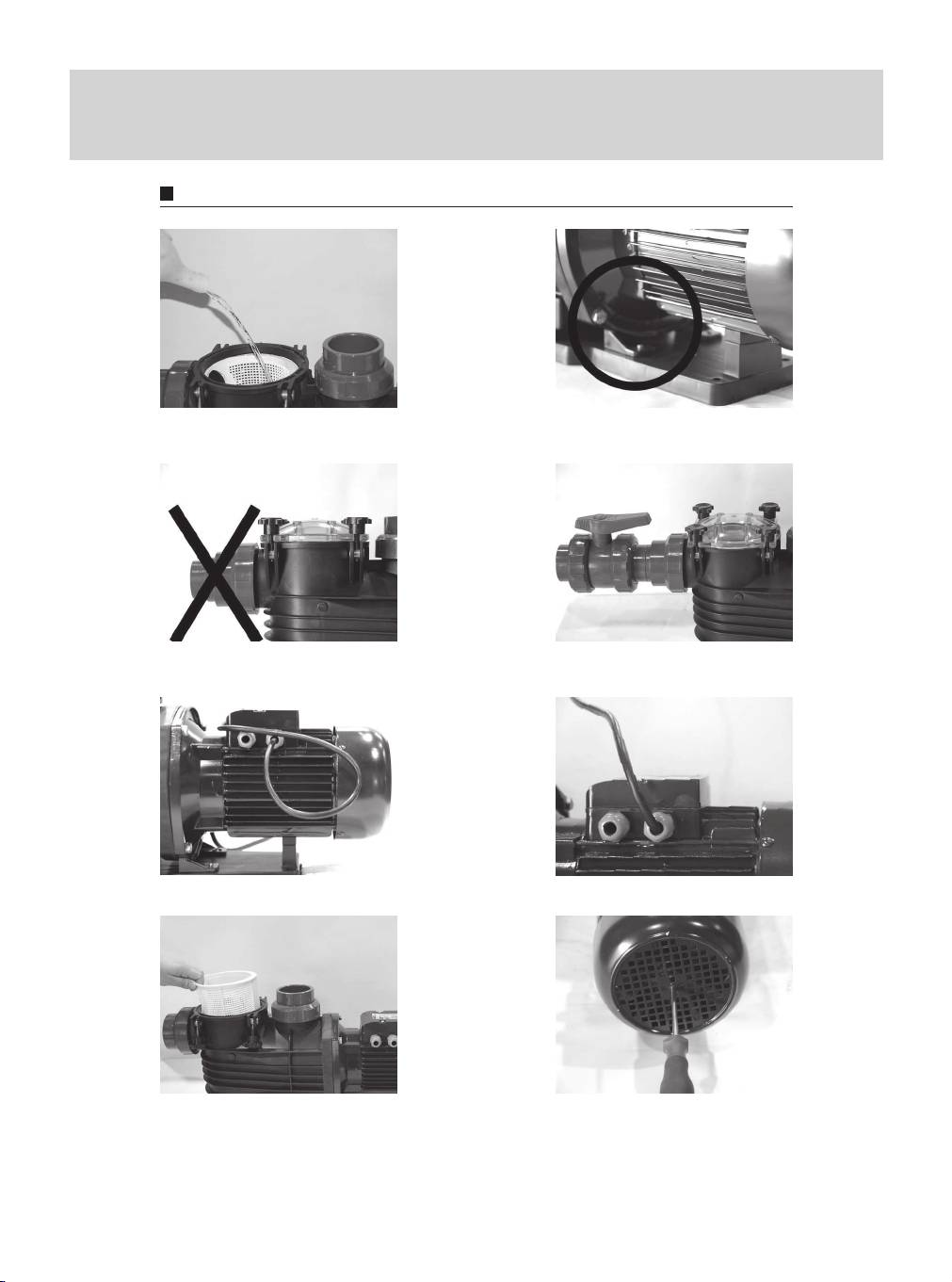
Make sure that the electrical supply is turned off before removing the connection box
cover or before any moving or disassembling of the pump.
The electrical connections must be performed by an authorised electrician and according to
the local standards.
The pump must be connected to an external switch.
The voltage and the frequency are marked on the characteristics plate. Make sure that the
motor is suitable for the electrical supply in use.
The motor must be connected to the electrical supply as shown in the drawing, using an ap-
proved, watertight cable and in accordance with local standards.
4Electrical connections
3.1 Ventilation
The pump motor is cooled by the fan on the rear. We will therefore preferably place the pump
in a WELL VENTILATED place (protected from possible freezing), preferably in a room.
a) If the pump is installed OUTDOORS, it must be protected from the rain and the elements
with a suitable cover.
b) If the pump is installed in an underground or semi buried plant housing, a SUFFICIENT AIR
ENTRY must be assured for the motor ventilation in order to not be damaged (the inside
temperature should not exceed 50ºC).
c) In order to assure efficient cooling , the minimum distance between fan cover and the wall
or another obstacle situated at the back side of the motor must be more than 2,5 times
than the fan diameter.
Instruction Manual for Series MAXI

Instruction Manual for Series MAXI
4.1 Motor protection
All single phase versions have a motor protector and do not need any additional protection.
Note: If the motor is overloaded, it will turn off automatically and will start to work again when
the temperature falls to a normal level.
All three-phase versions must be connected to an external motor protector.
The pump must be connected to the ground socket and the electrical installation must have
a differential circuit.
THREE-PHASE
TRIANGLE
connection:
lower tension
THREE-PHASE
STAR
connection:
higher tension
SINGLE PHASE
Line Line Line
Note: Do not start the pump until it has been primed and purged.
The pump is correctly primed when the water is just below the transparent cover.
The arrows on the pump housing indicate the correct rotation.
In order to create maximum suction capacity when starting, close the discharge valve, start
the pump and slowly open the discharge valve.
If the pump does not work correctly after 5 minutes, stop the pump, check the water level in
the suction pipe and in the pump.
5Starting
Make sure that the electrical power supply is turned off and can not be connected ac-
cidentally before starting work with the pump.
The pre-filter basket included in the pump must be checked every day and cleaned if nec-
essary. Before opening the pre-filter cover, close the charging and discharge valves.
After the cleaning, prime the pump again and close the pre-filter cover. The pump can
start work again.
Note: High pressure cleaning is not allowed.
6Pre-filter basket cleaning

GB
If the pump is not going to be used during the winter, it must be drained to avoid damage
caused by icing. To drain the pump, remove the pump drain plug (69) from the pump hous-
ing. Do not refit the draining screw until the pump is used again.
7Protection from ice
Under normal working conditions the pump needs no any specific maintenance.
8Maintenance
9Trouble shooting guide
Trouble Cause
1) The pump has not been filled with water
2) The pump has not been purged
3) Filtration in the suction pipe / hose
4) Incorrect closing of the transparent lid
- Check the pre-filter basket
- Tighten thumb screws of the lid equally
5) The suction is too high
- The maximum height allowed is 3m
6) The sum of the load losses from the installation
exceeds the pumping capacity
- Recalculate the pressure required
7) Mechanical seal leaking
1) Incorrect rotation direction (only three-phase
pumps)
- Change the rotating direction
2) The pre-filter basket or the skimmer are dirty or
blocked
- Clean the pre-filter basket
3) The water level in the swimming pool is too low
- Increase the water level up to the 1/2 of the
pool capacity
4) The suction pipe/hose is partially blocked by im-
purities
- Clean the suction pipe/hose
The pump works, but does not prime
The pump does not work satisfactorily
Instruction Manual for Series MAXI

Dimensions
Type
MAXI 15 M-T
MAXI 20 M-T
MAXI 30 T
MAXI 40 T
L
675
675
700
700
Dimensions

Components
MAXI 15M
MAXI 15T
MAXI 20M
MAXI 20T
1 Rotor shaft
2 Pump side motor bearing
3 Fan side motor bearing
4 Undulated pressure washer
5 Fan side motor cover
6 Stator housing
7 Connector
8 Fan
9 Motor screw
10 Fan cover
11 Ground screw
12 Single phase terminal plate
13 Terminal plate nut
14 Terminal plate screw
15 Single phase terminal box
16 Cable fixed support
17 Cable fixing support screw
18 Condenser
19 Terminal box screw
20 Single phase cable passage
21 Cable press bolt
22 Terminal box cover
23 Terminal box cover screw
26 Three phase terminal plate
27 Terminal plate bridge
28 Three phase terminal box
29 Three phase cable bolt
32 Terminal box gasket
38 Terminal box cover gasket
41 Nut capsule
43 Pump side motor seal
44 Fan side motor seal
47 Terminal plate washer
50 Drip washer
53 Filter pump housing washer
54 Key
55 Impeller
57 Impeller nut
58 Diffusser
61 Pump housing gasket
62 Pump housing
63 Pump housing bolt
64 Filter basket
65 Filter cover gasket
66 Filter cover
67 Filter thumb nut
68 Drain plug gasket
69 Drain plug
74 Dynamic part (mechanical
seal)
75 Static friction (mechanical
seal)
76 Gasket (mechanical seal)
76A Seal gasket
77 Fixing thumb nut
78 Intermediate housing
79 Base plate screw
80 Complete seal
90 Impulsion flange gasket
94 Suction flange gasket
111 Motor support
114 Pump bench base plate
123 Suction sleeve nut
124 Suction connection sleeve
125 Impulsion sleeve nut
126 Impulsion connection sleeve
COMPONENTS

MAXI 30T
MAXI 40T
1 Rotor shaft
2 Pump side motor bearing
3 Fan side motor bearing
4 Undulated pressure washer
5 Fan side motor cover
6 Stator housing
7 Connector
8 Fan
9 Motor screw
10 Fan cover
11 Ground screw
13 Terminal plate nut
14 Terminal plate screw
19 Terminal box screw
21 Cable press bolt
26 Three phase terminal plate
27 Terminal plate bridge
28 Three phase terminal box
29 Three phase cable bolt
30 Ball bearing retention ring
32 Terminal box gasket
33 Motor ball bearing cover
34 Ball bearing cover screw
35 Fan cover screw
37 Fan clamp
40 Complete press cable
44 Fan side motor seal
47 Terminal plate washer
49 Cable passage gasket
53 Filter pump housing washer
55 Impeller
57 Impeller nut
58 Diffusser
61 Pump housing gasket
62 Pump housing
63 Pump housing bolt
64 Filter basket
65 Filter cover gasket
66 Filter cover
67 Filter thumb nut
68 Drain plug gasket
69 Drain plug
74 Dynamic part (mechanical
seal)
75 Static friction (mechanical
seal)
76 Gasket (mechanical seal)
77 Fixing thumb nut
78 Intermediate housing
80 Complete seal
90 Impulsion flange gasket
94 Suction flange gasket
111 Motor support
114 Pump bench base plate
123 Suction sleeve nut
124 Suction connection sleeve
125 Impulsion sleeve nut
126 Impulsion connection sleeve
COMPONENTS
Components
This manual suits for next models
6
Table of contents
Popular Water Pump manuals by other brands

STI
STI SC/Vo instruction manual

Monarch
Monarch TSP 3 owner's manual

Xylem
Xylem Goulds 3642 instruction manual

Grundfos
Grundfos PS.G Series Installation and operating instructions

Goulds Pumps
Goulds Pumps 3935 Installation, operation and maintenance instructions

SPIDO
SPIDO PRO MAXINOX 700 operating instructions

Flotec
Flotec 1100X Series quick start guide

Aqua
Aqua HC 200 Programming instructions

Flotec
Flotec FPZT7300 owner's manual

AquaScape
AquaScape AquaBasin Installation & maintenance instructions

Solinst
Solinst 415 operating instructions

Texmo Industries
Texmo Industries Taro Pumps Borewell Instructions & operating manual