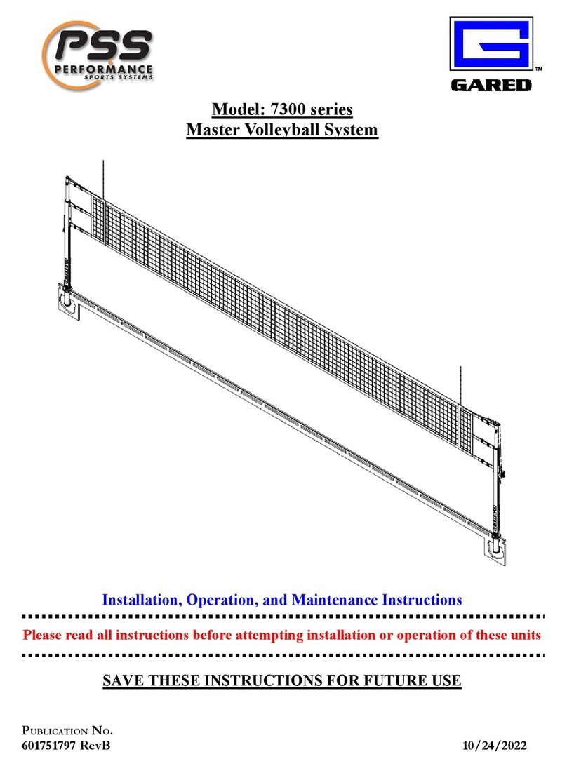
PSS ODVB40SQ Manual

OUTDOOR VOLLEYBALL
Model: ODVB40SQ
Installation, Operation, and Maintenan e Instru tions
Please read all instru tions before attempting installation or operation of these units
SAVE THESE INSTRUCTIONS FOR FUTURE USE
P
UBLICATION
N
O
.
601751809 04-02-20

OUTDOOR VOLLEYBALL ODVB40SQ
1
Table of Contents
Section Page No.
Introduction 1
Specifications / Dimensions 2
Parts List 3
Installation 4
Operation 8
Maintenance 10
INTRODUCTION
T ank you for your purc ase of a model ODVB40SQ Outdoor Volleyball Standards. To ensure
t at our equipment will provide years of use to you, we are including t is installation, operation,
and maintenance guide. T is guide will provide information on t e proper assembly and
installation met ods, operating procedures, and preventative maintenance of your portable
backstop.
Please note t at a Bill of Materials is being included wit t is guide. Please c eck t at all of t e
parts called out on t e Bill of Materials are present prior to beginning assembly and setup.
Please do not substitute for factory parts. Please contact t e factory customer service department
and allow t em to determine if substitute parts are acceptable.
It is recommended t at an individual w o as been properly trained perform assembly and set up
of t e w eel adapter kit. No one under t e age of 18 s ould attempt assembly or set up of t e
unit, unless properly supervised.
To prevent normal wear and tear from s ortening t e life of t e unit, preventative maintenance
inspections and repairs s ould be performed at least once per year. If t e units are subject to
ig or unusual usage, inspections s ould be sc eduled to occur more frequently. If items are
found to be nonconforming, replacements can be ordered from one of our aut orized dealers.
W en contacting your dealer, please ave information regarding t e name of t e project and any
applicable warranty information.

OUTDOOR VOLLEYBALL ODVB40SQ
2
SPECIFICATIONS & DIMENSIONS

OUTDOOR VOLLEYBALL ODVB40SQ
3
PARTS LIST
ITEM
QTY
PART NUMBER
DESCRIPTION
1
2
223-4-20-8SS
SCREW, MACH PAN HD PHIL 1/4-20 UNC X 0.
2
1
2 -10-24
HEX NUT, NYLON LOCK #10-24
3
4
02-6-16-12Z
HEX BOLT, 3/8-16 UNC X 0.7
4 1 06-4-20-10 BOLT, SHOULDER, SOC. HD 0.2 X 0.62
46- -18
SQUARE NUT /16-18
6
4
46-6-16
SQUARE NUT 3/8-16
7
48- -18Z
HEX NUT, SERRATED FLANGE /16-18
8
2
62-4Z
SPLIT LOCK WASHER 1/4
9
1
1029-22-00
SHEAVE
10
1
1031-22-00
SHEAVE BRACKET
11
3
1282-30-00
/16" UNIVERSAL SNAP LINK
12
1406-11-00
EYEBOLT, /16" X 1" STAINLESS
13
2
1016 3829
VINYL END CAP, 4" SQUARE WHITE
14
1
6016 3814
WINCH, OUTDOOR VOLLEYBALL
1
1
6016 1
PLATE, ODVB40SQ PULLEY MOUNT
16
2
604804113
4" SQUARE ODVB40SQ POST
17
2
6 16 420
ROPE RATCHET, 1/8"
18
1
6017 1810
MANUAL, ODVB40SQ INSTALLATION
20
REF
ODVBNET
NET, ODVB VOLLEYBALL 28' (8. m)
20
REF
ODVBNET32
NET, ODVB VOLLEYBALL 32' (9.7 M)
21
REF
6828
GROUND SLEEVE KIT, 4" SQUARE ODVB40SQ
22
REF
6829
CAP KIT, 4" SQUARE SLEEVE ODVB40SQ
Reference items #20, #21 and #22 are not included wit t e standards and must be ordered separately.

OUTDOOR VOLLEYBALL ODVB40SQ
4

OUTDOOR VOLLEYBALL ODVB40SQ
5
INSTALLATION
TOOLS REQUIRED
• 50 ft tape measure
• S ovel and concrete tools
• Level
• Cable cutters
• Wrenc es and socket set
• Box knife
• Concrete (minimum of 19 cubic feet)
for 20” dia. x 48” deep foundation.
FOUNDATION
Post Cast in Pla e
1. Locate and mark post centerlines. Post
centerline is determined by t e net size being
used.
a. Net ODVBNET is 28 ft long and
requires post centerline of 32 ft.
b. Net ODVBNET32 is 32 ft long and
requires post centerline of 36 ft.
2. Dig a ole at a minimum of 20” in diameter
and 48” deep.
3. Pour ole level wit concrete, w ile setting
t e Post, item to be 24” below t e finis ed
playing surface.
4. Be sure post is plumb and squared wit t e
slot in post facing t e court.
5. Slope top edges of concrete away from t e
centerline of post.
6. Allow concrete to cure for at least 24 ours
before continuing.

OUTDOOR VOLLEYBALL ODVB40SQ
2
Post Sleeve Option 6828
1. Post sleeve option model 6828 is required for
sleeve installation.
2. Locate and mark post centerlines. Post
centerline is determined by t e net size being
used.
a. Net ODVBNET is 28 ft long and
requires post centerline of 32 ft.
b. Net ODVBNET32 is 32 ft long and
requires post centerline of 36 ft.
3. Dig a ole at a minimum of 20” in diameter
and 48” deep.
4. Pour ole level wit concrete, w ile setting t e
sleeve, item #21, to be flus wit t e finis ed
playing surface.
5. Be sure sleeve is plumb and squared to t e
court.
6. Slope top edges of concrete away from t e
centerline of post.
7. Allow concrete to cure for at least 24 ours
before continuing.
Optional Sleeve Cap Kit, Model 6829, is available to
keep sand and debris out of sleeves w en posts are not
installed.

OUTDOOR VOLLEYBALL ODVB40SQ
3
POST AND NET INSTALLATION
1. Wit posts and or sleeves set and concrete cured, place t e end post and winc post into
t e sleeves wit t e eyebolts facing t e net side of eac post as pictured below.

OUTDOOR VOLLEYBALL ODVB40SQ
4
2. Connect t e top net cable to t e ig est
eye-bolt on t e end post using a quick link.
T e end of t e net wit t e s ortest cable
s ould be connected to t e end post.
3. Cut t e cable eye off t e top cable on t e
winc post end.
4. T read t e cable on t e winc post end
t roug t e pulley and down to t e winc .
5. Attac cable to t e winc cutting t e
excess winc cable to t e lengt . Use t e
instructions on page 9 to install cable to
winc . Note: t ere s ould be a minimum
of 3 wraps of cable on t e winc before it
begins tig tening.
6. Crank t e winc clockwise to tig ten t e
upper net cable. Do not overtighten the
net able. T e winc only tensions t e
cable to support t e net. T e net is
tensioned wit t e rope ratc ets.
7. Center t e net over t e court and tie t e net
ties to a quick link, attac ing quick links to
t e eyebolts on t e end post.
8. Hook t e rope ratc ets onto t e eye-bolts of
t e winc post and tig ten tie by feeding t e
net tie rope into t e ratc et and pulling on
t e loose rope end.

OUTDOOR VOLLEYBALL ODVB40SQ
5
OPERATION
1. Set posts into sleeves wit eye-bolts facing t e court.
2. Attac top net cable to t e end post wit a quick link at t e appropriate eye-bolt for t e
desired net eig t. See c art below. Note t at net eig t is measured at t e middle of t e
court.
3. T read t e cable on t e winc post end t roug t e pulley and down to t e winc .
Attac to winc using cable to winc instructions on t e following page.
4. Crank t e winc clockwise to tig ten net cable. Do
not over tighten able. T e winc only tensions t e
cable to support t e net. T e net is tensioned wit t e
rope ratc ets.
5. Connect net ties at t e end post using quick links.
6. Connect net ties, using t e rope ratc ets at t e winc post.
7. Pull loose end of rope on rope ratc ets to tig ten net. Press release on rope ratc et to
release net tension.
8. To adjust net eig t, loosen net ties and cable tension and adjust eye-bolts and pulley
bracket to t e desired eig t and t en retig ten. Tension net cable and tension net ties.
8. Volleyball system can be taken down by reversing t e setup procedure.

OUTDOOR VOLLEYBALL ODVB40SQ
6
Cable to win h installation
1. T read cable over t e drum and t roug t e drum side
slot.
2. Insert cable end t roug one side of cable clamp,
making a loop and returning t roug t e ot er side of
clamp as s own.
3. Tig ten cable clamp nut slig tly t en pull gently on cable
to tig ten loop.
4. Tig ten cable clamp.
5. Be sure t ere is a minimum of 3 wraps of cable on t e
winc drum before net cable begins to tig ten.
Note: Cable s ould wrap t e drum as s own in illustration and
tig tening t e net, crank turned clockwise, will turn t e spool
clockwise w en viewed from t e clamp side.

OUTDOOR VOLLEYBALL ODVB40SQ
7
MAINTENANCE
1. General inspection of equipment w en used s ould be performed to ensure no catastrop ic failures
ave occurred during t e course of use between yearly inspections.
2. It is recommended t at yearly inspections be conducted to determine if any bolts or any ot er
ardware as become worn or loosened. A sample c eck s eet as been provided for you in t is
guide.
3. During yearly inspections, all moving parts s ould be inspected w ile in operation. Key points to
look for include rotation points w ere bus ings contact metal, winc es, pulleys and quick links.
T e ropes s ould be looked at for any degradation or fraying.
4. Any loose bolts or nuts s ould be tig tened.
Replacement parts and / or service to t e equipment can be obtained from your local dealer or installer.
To find your local dealer, visit us online or contact customer service department at t e web address or
p one number listed on t e last page of t is manual.

OUTDOOR VOLLEYBALL ODVB40SQ
8

OUTDOOR VOLLEYBALL ODVB40SQ
9
Gared Holdings, LLC
Performan e Sports Systems Gared Sports
9200 E. 146
th
Street 9200 E. 146
th
Street
Noblesville, IN 46060 Noblesville, IN 46060
800-848-8034 800-325-2682
www.perfsports. om www.garedsports. om
Table of contents
Other PSS Sport & Outdoor manuals


