Puls dimension UC10.241 User manual

1 EN UC10 Instruction Manual EDLC DC-UPS Uninterruptible Power Supply
2 DE UC10 Bedienungsanleitung EDLC DC-USV Unterbrechungsfreie Stromversorgung
3 FR UC10 Manual d'instructions EDLC DC-UPS Alimentation sans interruption
4 ES UC10 Manual de instrucciones EDLC DC-UPS Fuente de alimentación sin interrupciones
5 IT UC10 Manuale di Istruzione EDLC DC-UPS Gruppo di continuità
6 PT UC10 Manual de Instruções EDLC DC-UPS Fonte de Alimentação Ininterruptível
UC10.241
UC10.242
Read this first! English 1
Before operating this unit please read this manual thoroughly and retain this manual for future reference! This device may only be installed and put into operation by qualified personnel. If damage or
malfunction should occur during operation, immediately turn power off and send unit to the factory for inspection. The unit does not contain serviceable parts. The tripping of an internal fuse is caused
by an internal defect. The information presented in this document is believed to be accurate and reliable and may change without notice. For any clarifications the English translation will be used.
Intended Use: This device is designed for installation in an enclosure and is intended for general use such as in industrial control, office, communication, and instrumentation equipment. Do not use
this device in equipment, where malfunction may cause severe personal injury or threaten human life.
WARNING Risk of electrical shock, fire, personal injury or death.
1) Turn power off before working on the device. Protect against inadvertent re-powering.
2) Make sure that the wiring is correct by following all local and national codes.
3) Do not modify or repair the unit.
4) Do not open the unit as high energy is present inside.
5) Use caution to prevent any foreign objects from entering the housing.
6) Do not use in wet locations or in areas where moisture or condensation can be expected.
7) The internal energy storage element can provide output power for up to 45 minutes after disconnecting the unit from the input.
Vor Inbetriebnahme lesen! Deutsch 2
Bitte lesen Sie diese Warnungen und Hinweise sorgfältig durch, bevor Sie das Gerät in Betrieb nehmen. Bewahren Sie die Anleitung zum Nachlesen auf. Das Gerät darf nur durch fachkundiges und
qualifiziertes Personal installiert werden. Bei Funktionsstörungen oder Beschädigungen schalten Sie sofort die Versorgungsspannung ab und senden das Gerät zur Überprüfung ins Werk. Das Gerät
beinhaltet keine Servicebauteile. Interne Sicherungen lösen nur bei Gerätedefekt aus. Die angegebenen Daten dienen allein der Produktbeschreibung und sind nicht als zugesicherte Eigenschaften
im Rechtssinne aufzufassen. Im Zweifelsfall gilt der englische Text.
Bestimmungsgemäßer Gebrauch: Dieses Gerät ist für den Einbau in ein Gehäuse konzipiert und zur Verwendung für allgemeine elektronische Geräte, wie z.B. Industriesteuerungen, Bürogeräte,
Kommunikationsgeräte oder Messgeräte geeignet. Benutzen Sie dieses Gerät nicht in Steuerungsanlagen, in denen eine Funktionsstörung zu schweren Verletzungen führen oder Lebensgefahr
bedeuten kann.
WARNUNG Missachtung nachfolgender Punkte kann einen elektrischen Schlag, Brände, schwere Unfälle oder Tod zur Folge haben.
1) Schalten Sie die Eingangsspannung vor Installations-, Wartungs- oder Änderungsarbeiten ab und sichern Sie diese gegen unbeabsichtigtes Wiedereinschalten.
2) Sorgen Sie für eine ordnungsgemäße und fachgerechte Verdrahtung.
3) Führen Sie keine Änderungen oder Reparaturversuche am Gerät durch.
4) Gerät niemals öffnen. Im Inneren befinden sich gefährliche Energien.
5) Verhindern Sie das Eindringen von Fremdkörpern, wie z.B. Büroklammern und Metallteilen.
6) Betreiben Sie das Gerät nicht in feuchter Umgebung oder in einer Umgebung, bei der mit Betauung oder Kondensation zu rechnen ist.
7) Der eingebaute Energiespeicher kann bis zu 45 Minuten nach der Abschaltung der Eingangsspannung den Ausgang des Geräts mit Energie versorgen.
A lire avant mise sous tension! Français 3
Merci de lire ces instructions de montage et d'entretien avant de mettre l'alimentation sous tension. Conservez ce manuel qui vous sera toujours utile. Cette alimentation doit être installée par du
personnel qualifié et compétent. Le déclenchement du fusible interne traduit très probablement un défaut au niveau de l'appareil. Si un défaut quelconque apparaît en cours de fonctionnement,
débrancher au plus vite l'alimentation. Dans ce deux cas de figure, il convient de faire contrôler l'alimentation en usine! Les données indiquées dans ce document servent uniquement à donner une
description du produit et n'ont aucune valeur juridique. En cas de divergences, le texte anglais fait foi.
Utilisation: Cet appareil est conçu pour être installé dans une armoire et pour tous les équipements électroniques, tel que l'équipement industriel de commande, l'équipement de bureau, le matériel
de communication et les instruments de mesures. N'utilisez pas cet appareil sur des installations dans lesquels un problème de fonctionnement de l'alimentation pourrait causer des blessures graves
ou menacer la vie humaine.
AVERTISSEMENT Prendre en compte les points suivants, afin d'éviter toute détérioration électrique, incendie, dommage aux personnes ou mort.
1) débrancher l'installation avant toute intervention sur l'alimentation (ou démontage) et s'assurer qu'il n'y a pas risque de redémarrage.
2) s'assurer que le câblage a été fait selon les prescriptions
3) ne pas effectuer de réparations ou modifications sur l'alimentation
4) ne pas ouvrir l'appareil. D’importantes énergies circulent à l'intérieur.
5) veiller à ce qu'aucun objet ne rentre en contact avec l'intérieur de l'alimentation (trombones, pièces métalliques)
6) ne pas faire fonctionner l'appareil dans un environnement humide ou à l'extérieur, non protégé. Ne pas utiliser l'appareil dans un environnement où il peut y avoir de la condensation.
7) L’accumulateur interne peut fournir une tension de sortie jusqu’à 45mn après la coupure de l’alimentation du module tampon.
Lea primero! Español 4
Conserve este manual como referencia para futuras consultas. La fuente de alimentación solo puede ser instalada y puesta en funcionamiento por personal cualificado. Por favor lea detenidamente
este manual antes de conectar la fuente de alimentación. Cuando se funde un fusible interno, existe gran probabilidad de un fallo interno en el equipo.Si se produce un fallo o mal funcionamiento
durante la operación, desconecte inmediatamente la tensión de alimentación. En ambos casos, el equipo debe ser inspeccionado en fábrica. La información presentada en este documento es
exacta y fiable en cuanto a la descripción del producto y puede cambiar sin aviso. En casa de duda, prevalece el texto inglés.
Uso apropiado: Este equipo ha sido diseñado para su instalación en un ambiente cerrado y ha sido concebido para uso general en instalaciones de control industrial, oficinas, comunicaciones y
equipos de instrumentación. No emplee esta unidad en equipos, donde un mal funcionamiento puede ocasionar lesiones graves o riesgo mortal.
ADVERTENCIA Riesgo de descarga eléctrica, incendio, accidente grave o muerte.
1) Desconectar la tensión de red antes de trabajar en la fuente de alimentación. Evite una posible reconexión involuntaria.
2) Asegurarse de que el cableado es correcto de acuerdo a los códigos locales y nacionales.
3) No realizar ninguna modificación o reparación de la unidad.
4) No abrir nunca la unidad. En el interior existe riesgo de alta energía.
5) Evitar la introducción en la carcasa de objetos extraños.
6) No usar el equipo en ambientes húmedos. No operar el equipo en ambientes donde se espere la formación de rocío o condensación.
7) El elemento almacenador de energía interno puede suministrar energía hasta 45 minutos después de desconectar la unidad de la tensión de entrada.

Leggere prima questa parte! Italiano 5
Prima di collegare il sistema di alimentazione elettrica si prega di leggere attentamente le seguenti avvertenze. Conservare le istruzioni per la consultazione futura. Il sistema di alimentazione elettrica
deve essere installato solo da personale competente e qualificato. In caso di intervento del fusibile interno, molto probabilmente l'apparecchio è guasto. Se durante il funzionamento si verificano
anomalie o guasti, scollegare immediatamente la tensione di alimentazione. In entrambi i casi è necessario far controllare l'apparecchio dal produttore! I dati sono indicati solo a scopo descrittivo del
prodotto e non vanno considerati come caratteristiche garantite dell'apparecchio.In caso di differenze o problemi è valido il testo inglese
Uso previsto: Questo apparecchio è previsto per il montaggio in un rack per moduli elettronici, ad esempio per controllori industriali, apparecchiature per ufficio, unità di comunicazione o apparecchi
di misura. Non utilizzare questo apparecchio in apparati o impianti dove il malfunzionamento può causare danni alla persona o pericolo di vita.
AVVERTENZA Il mancato rispetto delle seguenti norme può provocare folgorazione elettrica, incendi, gravi incidenti e perfino la morte.
1) Prima di eseguire interventi di installazione, di manutenzione o di modifica scollegare la tensione di rete ed adottare tutti i provvedimenti necessari per impedirne il ricollegamento non
intenzionale.
2) Assicurare un cablaggio regolare e corretto.
3) Non tentare di modificare o di riparare da soli l'apparecchio.
4) Non aprire l'apparecchio. Al suo interno sono applicate tensioni elettriche pericolose.
5) Impedire la penetrazione di corpi estranei nell'apparecchio, ad esempio fermagli o altri oggetti metallici.
6) Non far funzionare l'apparecchio in un ambiente umido. Non far funzionare l'apparecchio in un ambiente soggetto alla formazione di condensa o di rugiada.
7) L’energia interna accumulata ha un’autonomia fino a 45 minuti dalla sconnessione dell’ingresso.
Leia primeiro! Portuguès 6
Recomendamos a leitura cuidadosa das seguintes advertências e observações, antes de colocar em funcionamento a fonte de alimentação. Guarde as Instruções para futura consulta, em casos de
dúvida. A fonte de alimentação deverá ser instalada apenas por profissionais da área, tecnicamente qualificados. Se o fusível interno se fundir, é grande a possibilidade de existir um defeito no
aparelho. Se por acaso, durante a utilização ocorrer algum defeito de funcionamento ou dano, desligue imediatamente a tensão de alimentação. Em ambos os casos, será necessária uma
verificação na Fábrica! Os dados mencionados têm como finalidade somente a descrição do produto, e não devem ser interpretados como propriedades garantidas no sentido jurídico. Em caso de
duvidas aplica-se o texto em inglês.
Utilize: Este aparelho foi concebido para ser montado dentro de invólucros, caixas ou armários para aparelhos eletrônicos em geral, como, por exemplo, comandos de instalações industriais,
aparelhos para escritórios, aparelhos de comunicação ou instrumentos de medida e quadros eléctricos. Não utilize este aparelho em instalações, nos quais um defeito de funcionamento poderá
causar danos graves ou significar risco de morte.
ATENÇÃO A não observância ou o incumprimento dos pontos a seguir mencionados, poderá causar uma descarga elétrica, incêndios, acidentes graves ou morte.
1) Antes de trabalhos de instalação, manutenção ou modificação, desligue a tensão de alimentação, protegendo-a contra uma nova ligação involuntária.
2) As ligações devem ser efectuadas apenas por profissionais competentes.
3) Não efectue nenhuma modificação ou tentativa de reparação no aparelho. Quando necessário contacte o seu distribuidor.
4) Não abra o aparelho mesmo quando desligado. No seu interior existem condensadores que podem estar carregados electricamente.
5) Proteger a fonte de alimentação contra a introdução inadvertida de corpos metálicos, como por ex., clipes ou outras peças de metal.
6) Não usar o aparelho em ambientes húmidos. Não usar o aparelho em ambientes propensos a condensações.
7) O elemento de armazenamento de energia interna pode proporcionar potência de saída até 45 minutos depois de desligar o aparelho da entrada.
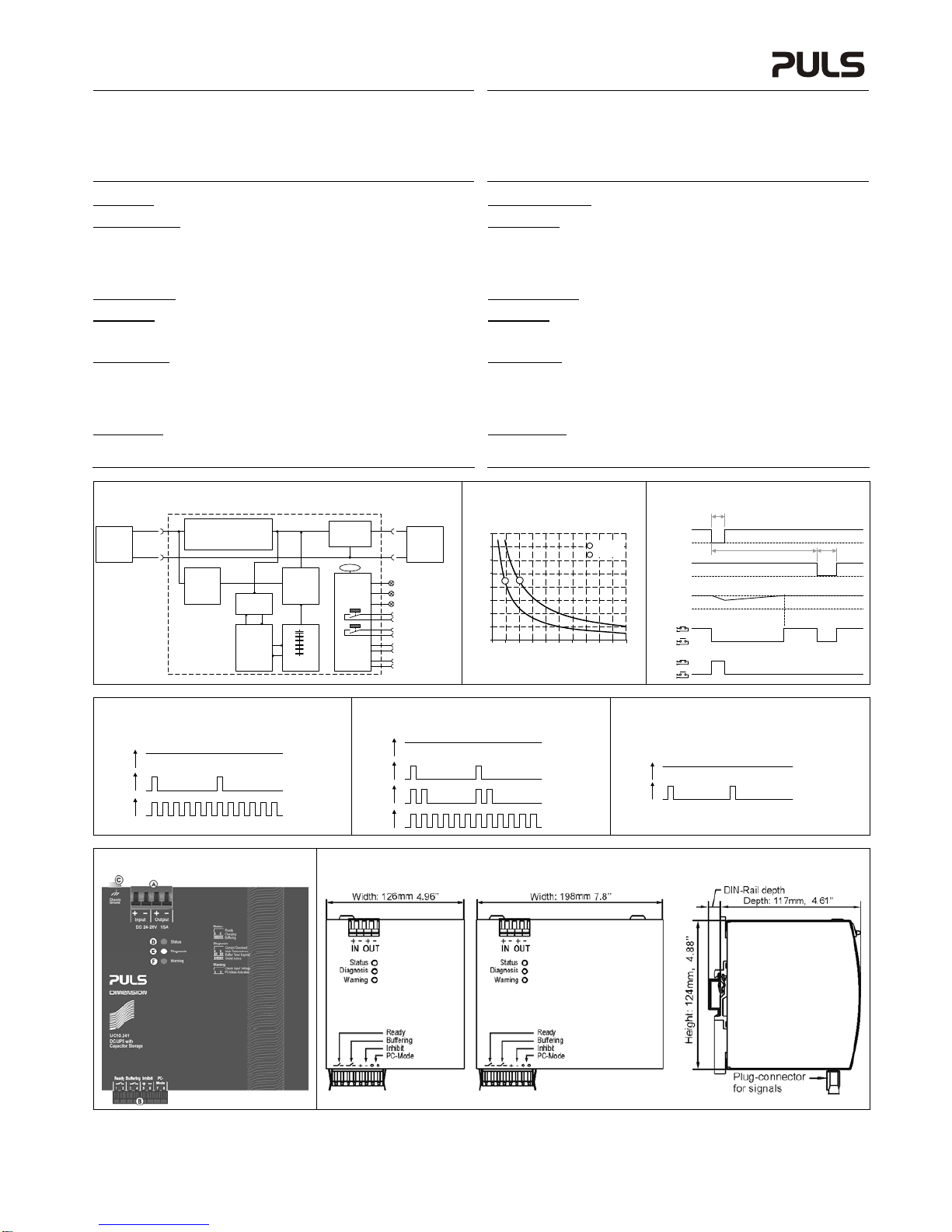
Product Description
These DC-UPSs utilize Electrochemical
Double Layer Capacitors (EDLC), which are
installed inside the unit. They can bridge
power failures or extend the hold-up time,
which allows for a safe shut-down of the
system. In times when the power supply
provides sufficient voltages, the DC-UPS
stores energy in the capacitors. In case of a
voltage fault, this energy is released to the
DC bus in a regulated process.
The DC-UPSs are maintenance-free and
have a typical lifetime expectancy >10
years, which is similar to one of a PULS
power supply. No regular replacement of
the capacitors is necessary as is required for battery based UPS systems. The wide temperature
range from -40°C to +60°C makes the unit suitable for many applications.
Produktbeschreibung
Diese DC-USVs verwenden
Doppelschichtkondensatoren (EDLC) als
Energiespeicher, welche bereits in das
Gerät eingebaut sind. Sie überbrücken
Spannungsfehler oder verlängern die
Haltezeit, um Vorgänge nach dem
Ausschalten kontrolliert beenden zu können
und einen anschließenden reibungslosen
Neustart sicherzustellen. Während das
Netzgerät Strom liefert, werden die
Kondensatoren geladen und speichern die
Energie. Versagt die Versorgung, wird
diese Energie wieder geregelt abgegeben.
Die DC-USVs benötigen keine Wartung. Die typische Lebenserwartung ist >10 Jahre, was
vergleichbar zu der von PULS Stromversorgungen ist. Der weite Arbeitstemperaturbereich von
-40°C bis +60°C qualifiziert diese Geräte für viele Anwendungen.
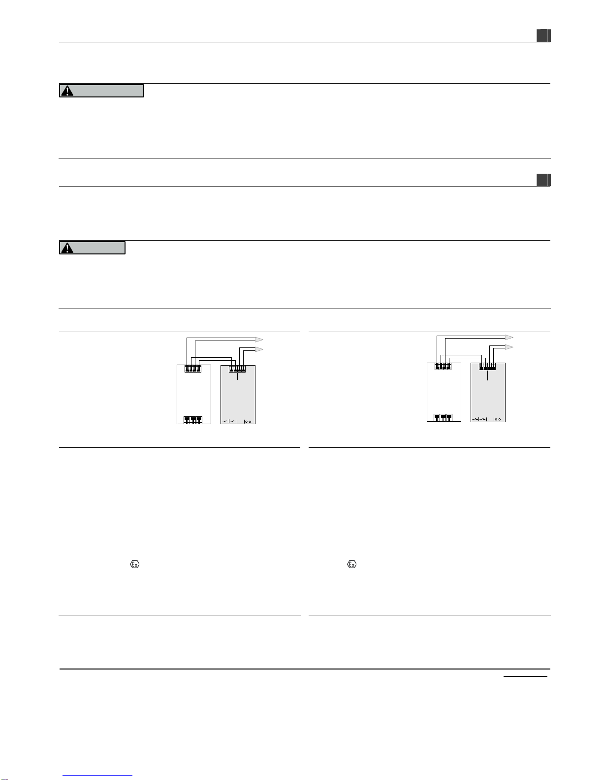
Installation
Mount the unit onto a DIN-rail according to EN 60715 (7.5 or 15mm height) or utilize the wall
mounting bracket ZM2.WALL. Observe correct installation orientation: power terminals must be
located on the top and the signal terminals on the bottom of the unit. Do not obstruct air flow as
the unit is convection cooled. Ventilation grid must be kept free of any obstructions. The following
installation clearances must be kept when the DC-UPS is permanently fully loaded:
Left / right: 5mm (15mm in case the adjacent device is a heat source)
40mm on top, 20mm on the bottom of the unit.
A disconnecting means shall be provided for the output of the DC-UPS when used in applications
according to CSA C22.2 No 107.1-01.
The input must be powered from a SELV source (according to IEC 60950-1), a PELV source
(according to IEC 62477-1) or an Isolated Secondary Circuit (according to UL 508).
Use in hazardous location areas
Units which are marked with "Class I Div 2" are suitable for use in Class I Division 2 Groups A, B,
C, D locations.
Units which are marked with II 3G Ex nA nC IIC T4 Gc are suitable for use in Group II
Category 3 (Zone 2) environments and are evaluated according to EN 60079-0 and EN 60079-15.
WARNING EXPLOSION HAZARDS!
Substitution of components may impair suitability for this environment. Do not disconnect the unit
or change unit settings unless power has been switched off or the area is known to be non-
hazardous. A suitable enclosure must be provided for the end product which has a minimum
protection of IP54 and fulfils the requirements of the EN 60079-15.
Installation
Das Gerät auf eine DIN-Schiene entsprechend EN 60715 (7,5 oder 15mm Höhe) oder mit dem
Wandmontagezubehör ZM2.WALL so montieren, dass sich die Leistungsanschlüsse oben und die
Signalanschlüsse unten befinden. Das Gerät ist für Konvektionskühlung ausgelegt, daher
Luftzirkulation nicht behindern! Folgende Einbauabstände sind bei dauerhafter Volllast
einzuhalten:
Links / rechts: 5mm (15mm bei benachbarten Wärmequellen)
Oben: 40mm, unten 20mm vom Gerät.
Bei Anwendungen nach CSA C22.2 No 107.1-01 muss der Ausgang der DC-USV mit einer
Trennvorrichtung versehen werden.
Der Eingang muss von einer Spannungsquelle versorgt werden, welche entweder den SELV
(gemäß IEC 60950-1), PELV (gemäß IEC 62477-1) oder den „Isolated Secondary Circuit“ (gemäß
UL 508) Anforderungen genügen.
Betrieb in explosionsgefährdeter Umgebung
Geräte, die mit "Class I Div 2" gekennzeichnet sind, sind für den Einsatz in Klasse I Division 2
Gruppen A,B,C,D Umgebung geeignet.
Geräte, die mit II 3G Ex nA nC IIC T4 Gc, gekennzeichnet sind, sind nach EN 60079-0 und
EN 60079-15 getestet und kann in Gruppe II, Kategorie 3 (Zone 2) Umgebungen verwendet
werden.
ACHTUNG EXPLOSIONSGEFAHR!
Veränderungen am Gerät können die Tauglichkeit für diese Umgebung beeinträchtigen.
Anschlüsse nicht abklemmen und Geräteeinstellung nicht verändern, solange Spannung anliegt
oder die Umgebung als explosionsgefährlich gilt. Das Gerät muss mindestens in ein IP54
Gehäuse, welches den Anforderungen der EN 60079-15 entspricht, eingebaut werden.
Germany +49 89 9278 0 www.pulspower.de Austria +43 27 64 32 13 www.pulspower.at
China +86 512 62881820 www.pulspower.cn Singapore +65 6684 2310 www.pulspower.sg
France +33 478 668 941 www.pulspower.fr Switzerland +41 56 450 18 10 www.pulspower.ch
North America +1 630 587 9780 www.pulspower.us United Kingdom +44 1525 84 1001 www.pulspower.co.uk
Headquarters:
PULS GmbH
Elektrastrasse 6
81925 Munich, Germany
L N PE
+ +
- -
Power
Supply
24V Output
Input
UC10
DC-UPS
+
-
IN
+
-
OUT
Ready
Buffering
Inhibit
+
-
PC-Mode
buffered
branches
non-buffered
branches
L N PE
+ +
- -
Netzgerät
24V Ausgang
Eingang
UC10
DC-USV
+
-
Ein
gang
+
-
Aus
gang
Ready
Buffering
Inhibit
+
-
PC-Mode
gepufferte
Lasten
ungepufferte
Lasten

UC10 Instruction Manual UC10 Bedienungsanleitung
Technical Data 1) Technische Daten
1) UC10.241 UC10.242
Input Voltage Eingangsspannung nom. DC 24V -20%/+25% DC 24V
-20%/+25%
Input Voltage Range Eingangsspannungsbereich 22.5 – 30Vdc 2)
19.2 - 35Vdc3) 22.5 – 30Vdc 2)
19.2 - 35Vdc3)
Turn-on Voltage Einschaltspannung typ. / max. 22.8V / 23.0V 22.8V / 23.0V
Input Current 4) Eingangsstrom
4) max. 0.1A / 1.3A / 17A 0.1A / 1.3A / 17A
Return Current to Input 5) Rückwärtsstrom in den Eingang 5) max. -11mA -11mA
Transfer Threshold Voltage 6) Schwellspannung für Pufferbetrieb 6) typ. 22.45V (0A load)
22.55V (10A load)
22.60V (15A load)
22.45V (0A load)
22.55V (10A load)
22.60V (15A load)
Output Voltage in Normal Mode Ausgangsspannung Normalbetrieb nom. Input – 0.3V (10A load)
Input – 0.45V (15A load) Input – 0.3V (10A load)
Input – 0.45V (15A load)
in Buffer Modes Pufferbetrieb typ. 22.45V (0A buffer current)
22.25V (10A buffer current)
22.12V (15A buffer current)
22.45V (0A buffer current)
22.25V (10A buffer current)
22.12V (15A buffer current)
Output Current Ausgangsstrom nom. 15A 15A
Output Power Ausgangsleistung nom. 360W 360W
Output Overload Behavior Überlastverhalten am Ausgang - continuous current continuous current
Capacitor Size Größe der Kondensatoren nom. 6kWs 12kWs
Charging Time Ladezeit 16 minutes 32 minutes
Buffer Time Pufferzeit 200s at 1A
16.5s at 10A
9s at 15A
400s at 1A
33s at 10A
18s at 15A
Efficiency Wirkungsgrad typ. 97.8% 97.8%
Power Losses Verlustleistung typ. 2.9W (0A load)
5.5W (10A load)
7.7W (15A load)
2.9W (0A load)
5.5W (10A load)
7.7W (15A load)
Operational Temperature Range 8) Betriebstemperaturbereich
8) nom. -40°C - +60°C -40°C - +60°C
Storage Temperature Range Lagertemperaturbereich nom. -40°C - +70°C -40°C - +70°C
Humidity 7)Feuchte
7) IEC 60068-2-30 5 - 95% r.H. 5 - 95% r.H.
Vibration Schwingen IEC 60068-2-6 2g 10) 2g 10)
Shock Schocken IEC 60068-2-27 30g 6ms, 20g 11ms 10) 30g 6ms, 20g 11ms 10)
Degree of Pollution Verschmutzungsgrad IEC 62477-1, IEC 60950-1 2 7)27)
Degree of Protection Schutzart EN 60529 IP20 IP20
Class of Protection Schutzklasse IEC 61140, IEC 60950-1 III III
Over-voltage Category Überspannungskategorie IEC 62477-1, IEC 60950-1 II II
Over-temperature Protection Übertemperaturschutz OTP Yes / Ja Yes / Ja
Output Over-voltage Protection Überspannungsschutz am Ausgang OVP, max. 35Vdc 35Vdc
Parallel Use for higher currents
for redundancy
for longer buffer times
Parallel schaltbar für höhere Ströme
zur Redundanz
längere Pufferzeiten
-
-
-
No / Nein
Yes / Ja
Yes / Ja
No / Nein
Yes / Ja
Yes / Ja
Dimensions 9) (WxHxD) Abmessungen
9) (BxHxT) nom. 126x124x117mm 198x124x117mm
Weight Gewicht max. 1150g, 2.54lb 1720g, 3.79lb
1) All parameters are specified at 24Vdc input voltage, nominal output current, 25°C ambient
and after a 5 minutes run-in time unless otherwise noted.
2) Describes the voltage range where capacitors get charged and buffering is possible
3) Describes the voltage range where indicators and signaling are working
4) Capacitors charged and output not loaded / during charging and output not loaded / during
charging and output loaded with nominal current
5) Leakage current to input in buffer mode
6) The transfer threshold voltage describes the input voltage, where the unit switches into buffer
mode and delivers output voltage from the capacitors if the input was above the turn-on level
before and all other buffer conditions are fulfilled. The unit switches back to normal mode, as
soon as the input voltage exceeds the transfer threshold voltage again.
7) Do not energize while condensation is present.
Caution: For use in a controlled environment according to CSA 22.2 No 107.1-01.
8) The operational temperature range equals the surrounding air temperature measured 2cm
below the unit.
9) Depth without DIN-rail
10)Higher levels possible when utilizing the wall mounting bracket ZM2.WALL.
1) Alle Werte gelten bei 24Vdc Eingangsspannung, Nennausgangsstrom, 25°C Umgebung und
nach einer Aufwärmzeit von 5 Minuten, falls nichts anderes angegeben.
2) Beschreibt den Spannungsbereich bei dem ein Aufladen und eine Pufferung stattfinden kann.
3) Beschreibt den Spannungsbereich, in dem Signalisierung und Anzeigeelemente arbeiten.
4) Kondensatoren geladen und Ausgang unbelastet / Kondensatoren werden geladen und
Ausgang unbelastet / Kondensatoren werden geladen und Ausgang mit Nennstrom belastet.
5) Leckstrom am Eingang während des Pufferbetriebs
6) Die Schwellspannung für den Pufferbetrieb beschreibt de Eingangsspannung, bei der das
Gerät in den Pufferbetrieb umschaltet und die Energie aus den Kondensatoren zur Verfügung
stellt. Vorher musste der Eingang über der Einschaltspannung gewesen sein und alle
weiteren Pufferbedingungen erfüllt gewesen sein. Das Gerät schaltet wieder in den
Normalbetrieb, sobald die Eingangsspannung diesen Schwellwert übersteigt.
7) Nicht betreiben, solange das Gerät Kondensation aufweist. In Anwendungen nach CSA 22.2
No 107.1-01: Vorsicht - Verwendung nur in „controlled environment“
8) Die Betriebstemperatur wird 2cm unterhalb des Geräts gemessen.
9) Tiefe ohne DIN-Schiene
10)Höhere Werte sind bei Verwendung des Wandmontageadapters ZM2.WALL möglich.
CE Marking
CE mark is in conformance with EMC directive.
EMC Immunity: EN 61000-6-1, EN 61000-6-2
EMC Emission: EN 61000-6-3, EN 61000-6-4, FCC Part 15 Class B
CE Kennzeichnung
Das CE Zeichen ist angebracht und erklärt die Erfüllung der EMV Richtlinie.
Störfestigkeit: EN 61000-6-1, EN 61000-6-2
Störaussendung: EN 61000-6-3, EN 61000-6-4, FCC Part 15 Klasse B
Terminals and Wiring
Use appropriate copper cables that are designed for a minimum operating temperature of:
60°C for ambient temperatures up to 45°C,
75°C for ambient temperatures up to 60°C.
Follow national installation codes and regulations! Ensure that all strands of a stranded wire enter
the terminal connection! Ferrules are allowed.
Input / Output Signals
Spring-clamp terminal Plug-connector
Solid wire max. 6mm2 max. 1.5mm2
Stranded wire max. 4mm2 max. 1.5mm2
American wire gauge max. AWG 10 max. AWG 14
Wire diameter (including ferrules) max. 2.8mm max. 1.5mm
Wire stripping length 10mm / 0.4inch 8mm / 0.3inch
Tightening torque N/A (spring-clamp) N/A (spring-clamp)
Anschlussklemmen und Verdrahtung
Verwenden Sie geeignete Kupferkabel, die mindestens für:
60°C bei einer Umgebungstemperatur bis zu 45°C,
75°C bei einer Umgebungstemperatur bis zu 60°C zugelassen sind.
Beachten Sie nationale Bestimmungen und Installationsvorschriften! Stellen Sie sicher, dass
keine einzelnen Drähte von Litzen abstehen. Aderendhülsen sind erlaubt.
Eingang / Ausgang Signale
Federkraftklemme Steckverbinder
Starrdraht max. 6mm2 max. 1,5mm2
Litze max. 4mm2 max. 1,5mm2
AWG max. AWG 10 max. AWG 14
Drahtdurchmesser (inkl. Aderendhülsen) max. 2,8mm max. 1,5mm
Abisolierlänge 7mm / 0,28inch 8mm / 0,3inch
Anzugsdrehmoment - (Federkraftklemme) - (Federkraftklemme)

UC10 Instruction Manual UC10 Bedienungsanleitung
PC Mode (see Fig. 3)
The PC-mode always turns the output off for at least 5s after a buffer event lasting longer than 1s,
independent of whether the 24V may have recovered during this time. This function ensures that
the PC gets a restart signal. To activate the PC-mode, connect the two pins marked with “PC-
mode” together on the signal connector.
Fig. 3 shows an example, where the buffer event ends before the buffer capacitors are fully
discharged. After 35s of the beginning of the buffer event, the output of the DC-UPS will be
switched off for 5s.
PC-Mode (siehe Bild 3)
Der PC-Modus schaltet nach jedem Pufferfall >1s den Ausgang für mindestens 5s ab, unabhängig
davon, ob sich zwischenzeitlich die 24V erholt hat oder nicht. Damit wird sichergestellt, dass der
PC ein Reset Signal bekommt und wieder starten kann. Der PC-Mode wird durch ein Verbinden
der zwei Pins am Signalstecker aktiviert.
Bild 3 zeigt ein Beispiel, bei dem der Pufferfall endet, bevor die Kondensatoren vollständig
entladen sind. 35s nach dem Start des Pufferfalls wird der Ausgang der DC-USV für 5s
abgeschaltet.
User Interface (see Fig. 7)
A Power Port (Quick-connect spring-clamp terminals)
To connect the input power and the buffered loads
B Signal Connector (pluggable screw terminal)
- Ready: Contact is closed when status LED shows “Ready”
- Buffering: Contact is closed during buffering
Contact ratings: max. 60Vdc 0.3A, 30Vdc 1A, 30Vac 0.5A
- Inhibit input: A voltage between 10 and 35V applied on this input signal disables buffering
(e.g. during service)
- PC Mode: To activate the PC-mode connect the two pins of the signal connector together
C Chassis Ground (screw)
Use a M4 ring-type terminal to connect the housing to ground, when required
D Status LED (green, see figure 4 for flashing pattern)
- Ready: Capacitors fully charged, no failures detected
- Charging: Capacitors being charged
- Buffering: Capacitors being discharged
D Diagnosis LED (yellow, see figure 5 for flashing pattern)
- Current Overload: Too high output current, output voltage falls below 20Vdc, ready contact
opens
- High Temperature: Indicates a capacitor temperature higher than 65°C, charging and
buffering remains possible, ready contact opens.
- Buffer Time Expired: Buffering stopped due to discharged capacitors
- Inhibit Active: Buffering is blocked by the inhibit signal
E Warning LED (red, see figure 6 for flashing pattern)
- Check Input Voltage: Indicates a too low or too high input voltage. The input voltage must
be between 23Vdc and 30Vdc to turn the output on and to start charging of the capacitors.
- PC-Mode Activated: Indicates that PC-Mode is activated.
Benutzerinterface (siehe Bild 7)
A Leistungsanschlüsse (Schnellanschluss Federkraftklemmen)
Zum Anschluss der Versorgung und der gepufferten Verbraucher
B Signalstecker (steckbare Schraubklemme)
- „Ready“: Kontakt ist geschlossen, wenn die Status LED “Ready” anzeigt
- „Buffering“: Kontakt ist im Pufferbetrieb geschlossen
Kontaktbelastbarkeit: max. 60Vdc 0,3A, 30Vdc 1A, 30Vac 0,5A
- „Inhibit input“: Eine Spannung zwischen 10 und 35V an diesem Eingang verhindert einen
Pufferbetrieb (z.B. bei Servicearbeiten)
- „PC-Mode“: Der PC-Mode ist aktiviert, wenn die zwei Anschlusspins verbunden sind.
C „Chassis Ground“ (Schraube)
Wenn erforderlich, kann hier das Gehäuse mit einem M4 Ringkabelschuh geerdet werden.
D Status LED (grün, siehe Bild 4 für Blinkmuster)
- „Ready“: Kondensatoren voll geladen, keine Fehler erkannt
- „Charging“: Kondensatoren werden geladen
- „Buffering“: Kondensatoren werden entladen
D Diagnose LED (gelb, siehe Bild 5 für Blinkmuster)
- „Current Overload“: Zu hoher Ausgangsstrom, Ausgangsspannung kleiner 20Vdc, Ready
Kontakt ist offen.
- „High Temperature“: Zeigt an, wenn die Temperatur der Kondensatoren größer 65°C ist,
Lade- und Pufferbetrieb ist möglich, Ready Kontakt ist offen.
- „Buffer Time Expired“: DC-USV wurde aufgrund entladener Kondensatoren beendet.
- „Inhibit Active“: Ein aktiviertes Signal verhindert Pufferbetrieb
E „Warning“ LED (rot, siehe Bild 6 für Blinkmuster)
- “Check Input Voltage”: Zeigt zu geringe oder zu hohe Eingangsspannung an. Diese muss
zwischen 23-30Vdc sein, um den Ausgang einzuschalten und den Ladevorgang zu starten.
- “PC-Mode Activated”: Zeigt einen aktivierten PC-Modus an.
Fig. 1 / Bild 1
Functional Diagram / Funktionsschaltbild Fig. 2 / Bild 2
Buffer Time / Pufferzeit Fig. 3 / Bild 3
PC-Mode / PC-Mode
-
+
24V
Power
Supply
Boost
Converter
(Step-up
Converter)
Charger
Balancing
&
Safety
Circuits
Input
Electronic
Current
Limiter
+
-
Buffered
Load
Output
Diagnosis LED
(yellow)
Status LED
(green)
+
Controller
Warning
(red)
Buffering Contact
Ready Contact
(5)
-
(6)
(1)
(2)
(3)
(4)
Storage
Capacitors
Input Fuse,
Reverse Polarity Protection,
Return Current Protection
Temp
Input
Voltage
Monitor
Inhibit
(7)
(8)
PC-Mode
Buffer Current
0 20 200s40 60 80 100 120 140 160 180
Buffer Time
ab
0
6A
4A
16A
8A
2A
10A
12A
14A UC10.241
UC10.242
a
b
>1s
Power
Supply
Output
DC-UPS
Output
full
empty
Capacitor
Ready Contact
closed
open
Buffering Contact
closed
open
5s
35s
Fig. 4 / Bild 4
Flashing Pattern for green status LED/
Blinkmuster für grüne Status LED
Fig. 5 / Bild 5
Flashing Pattern for yellow diagnosis LED/
Blinkmuster für gelbe Diagnose LED
Fig. 6 / Bild 6
Flashing Pattern for red alarm LED/
Blinkmuster für rote Alarm LED
Ready
1
0
1
0Charging
1
0Buffering
1
0Current
Overload
1
0High
Temperature
1
0Buffer time
expired
1
0Inhibit
active
Check input
voltage
1
0
1
0PC-Mode
activated
Fig. 7 / Bild 7
User Interface/ Benutzerinterface Fig. 8 / Bild 8 Dimensions / Abmessungen
UC10.241 UC10.242 UC10.241, UC10.242
PU-406.010.50-10C (2016-02) The information in this document is believed to be accurate and reliable and may change without notice.
This manual suits for next models
1
Popular UPS manuals by other brands

Xtreme Power Conversion
Xtreme Power Conversion XPRT-6kVA User & installation manual

Eaton
Eaton 9E Installation and operation manual

SolarEdge
SolarEdge Gamatronic B120US installation guide

Huawei
Huawei iBAT 2.0-CIM01C2 quick guide

Powerbank
Powerbank GO-1000 user manual

Staco Energy
Staco Energy FLP-10-POPC-5-R-4Y-2Y user manual