PULSE+ CLEI PBB1GF0D User manual

Practice Section 1650
Issue 1, March 2011
-48 VDC TELECOMMUNICATIONS POWER SYSTEM
POWER NODE/30
CLEI™ Code PBB1GF0D
Trademarks used in this manual:
CLEI is a trademark of Telcordia Technologies, Incorporated.
EnerSys is a registered trademark and PowerSafe is a trademark of EnerSys Incorporated.
GMT is a trademark of Bussman Corporation.
MATE-N-LOK is a trademark of AMP Incorporated.
Pulsecom is a registered trademark of Hubbell Incorporated.
©2011 Pulse Communications Incorporated. All rights reserved.
1
CONTENTS PAGE
1. INTRODUCTION................................................1
A. Reason for Reissue.........................................1
B. Description ......................................................2
C. Features..........................................................2
2. APPLICATIONS.................................................2
3. FUNCTIONAL DESCRIPTION...........................3
4. INSTALLATION..................................................5
A. Selecting the Site ............................................5
B. Mounting the Power Node/30..........................6
C. Making Power and Battery Connections.........9
D. Using Auxiliary Power ...................................13
5. SPECIFICATIONS ...........................................14
6. MAINTENANCE...............................................15
7. CUSTOMER SERVICE....................................20
1. INTRODUCTION
This practice describes the Pulsecom® Power Node/30, a –48 VDC Telecommunications Power System,
shown in Figure 1. Installation and engineering references are included.
A. Reason for Reissue
This practice has been released to production.
Figure 1. Power Node/30 System Shown with
User-Supplied Batteries Installed

Power Node/30
1650, Issue 1, March 2011
2
B. Description
The Power Node/30 is a power building block that supports a wide range of small to medium outside plant
(OSP) telecommunication power applications. The system delivers a temperature-compensated, nominal
–48 VDC output to extend the life of customer provided, sealed, lead-acid batteries that, in turn, provide a
power reserve during electrical outages. The system is sized to accept four EnerSys®PowerSafe™SBS40
lead-acid batteries (not supplied).
Power Node/30 ordering codes are listed in Table 1.
Table 1. Power Node/30 Ordering Information
Ordering Codes Description
Power Node/30 Power system without factory-installed fuse panel (PNFP)
Power Node/30UF Power system with factory-installed PNFP
PN-POLE-STABILIZER Power Node pole-mounting stabilizer
NOTE 1: Batteries are not included.
NOTE 2: Refer to Pulsecom Practice Section 1603 for details on the Power Node Fuse Panel
NOTE 3: Refer to Pulsecom Practice Section 1674 for details on the PN-POLE-STABILIZER.
C. Features
The Power Node/30 provides the following features:
•Simple, compact, durable, flexible, cost-effective power system
•14-gauge steel NEMA Type 4 enclosure
•1/4-turn, tamper-resistant latch designed to accept a user-supplied padlock
•Integral wall-mounting brackets
•Accommodates four EnerSys PowerSafe SBS40, 38AH, 12V or equivalent batteries equipped with M6
threaded stud and nut terminals
•Battery heater
•Ability to replace the power supply module without removing the rear panel
•6-Ampere maximum power supply module current for rapid battery charging
•Temperature-hardened for use in outside plant applications
•Automatic temperature-compensated battery float charging
•Low voltage battery disconnect
•Power, charging, and fuse status LEDs
•Power plug that can be removed from AC outlet and connected to external generator
•Dual output
•Heavy-duty surge protection
•–48V power/alarm wiring strain-relief fitting
•Two groups of four 2A fused outputs when equipped with the PNFP
2. APPLICATIONS
The Power Node/30 supports legacy and state-of-the-art technologies, such as fiber, xDSL, pair gain, radio,
and satellite receiver systems. The system is especially well suited for MDU high-speed service applications.

Power Node/30
1650, Issue 1, March 2011
3
3. FUNCTIONAL DESCRIPTION
Figure 2 shows a typical functional diagram of the Power Node/30. Table 2 describes the Power Node/30
connectors shown in Figure 3 and Figure 4.
Figure 2. Power Node/30 Functional Diagram
Table 2. Power Node/30 Connections
Power Supply Module
Connector Function
BATTERY STRING 8-Pin MATE-N-LOK™ battery string connection
BATTERY, 10A 10-Ampere battery GMT™ fuse for safety overload protection.
–48V (1) 7.5-Ampere GMT fuse for –48V (1) output. See NOTE.
–48V (2) 7.5-Ampere GMT fuse for –48V (2) output. See NOTE.
OUTPUT TERMINAL Screw terminals for load connection (–48V, RTN, ALM).
NOTE: The Power Node/30 is equipped with a 7.5-ampere output fuse installed for each of two
–48V outputs and one spare 7.5-ampere fuse. If only one output is utilized, then the unused
–48V fuse must remain installed to suppress the open-fuse alarm function. In any case, do not
exceed the maximum current draw of 6.0 amperes.
PNFP Connector Function
A –48V (1), (2), (3), (4) Screw terminals (four) for GROUP A –48V.
A RTN (1), (2), (3), (4) Screw terminals (four) for GROUP A Return.
B –48V (1), (2), (3), (4) Screw terminals (four) for GROUP B –48V.
BRTN (1), (2), (3), (4) Screw terminals (four) for GROUP B Return.

Power Node/30
1650, Issue 1, March 2011
4
Figure 3. Power Node/30 – Front View

Power Node/30
1650, Issue 1, March 2011
5
Figure 4. Power Node/30 – Bottom View
4. INSTALLATION
A. Power Node Parts
•Power Node Plus Accessory Kit
oTwo 1/4-20 X 3/16” stainless steel pan head screws
oFour 1/4 external tooth lock washers
oOne 10 Amp GMT fuse
oOne 7.5 Amp GMT fuse
oOne 3/4” case hardened conduit locknut
oOne 12-1 AWG 2-hole 1/4” copper ground lug
oOne ground lug with rigid mounting bar
oOne 2-hole tongue No. 6 compression ground lug
oTen 7.4” long nylon 6.6 cable ties
oOne 3/4” Liquidtight conduit cord grip connector

Power Node/30
1650, Issue 1, March 2011
6
B. Selecting the Site
The location of the system should be selected with care to prevent hazards to the general public, to provide
safe and efficient working conditions for company personnel, and to maintain reasonable security to
company property. The selected location should be high enough to prevent surface water from flooding the
equipment. Consider the accessibility of both present and future feeder plants, reasonable access by company
personnel, and safe parking for vehicles. To improve battery life, it is suggested (where possible) that the
system be installed in a location that minimizes exposure to direct sunlight.
WARNING
Always call local utilities to verify locations of any buried cables or pipe lines prior to any site
work
Prior to installation, arrange for local AC service to the cabinet. In many cases, a power meter and a circuit
breaker will be required by the local power company. The Power Node/30 requires an individually protected
120 VAC, 60 Hz, 15 Ampere service.
WARNING
Have an electrician install and connect AC power in accordance with the NEC (National
Electric Code) and local codes, as applicable.
AC power to the cabinet should be provided as soon as possible after installation because the normal heat
generated by the electronic circuits during operation provides substantial protection against humidity.
If the cabinet must be unpowered for more than a few days, a 25 Watt incandescent light bulb, plugged into
the AC outlet, should be used to protect against condensation.
C. Mounting the Power Node/30
Pole Mounting
Procedures for pole mounting assume the use of the PN-POLE-STABILIZER pole mounting bracket to
minimize Power Node rocking. Refer to Table 1.
The following installer-provided hardware is required to mount the cabinet to a pole:
•Four machine hex head bolts (3/8" — 16 UNC ×3/4")
•Four split lock washers (3/8")
•Four flat washers (3/8")
•Four hex nuts (5/8" — 11 UNC)
•Four split lock washers (5/8")
•Four flat washers (5/8")
•Two threaded rods (5/8" — 11 UNC) long enough to reach through the mounting pole plus 5 inches
Follow Procedure 1 to install the Power Node/30 on a pole.

Power Node/30
1650, Issue 1, March 2011
7
Procedure 1. Pole-Mounting the Power Node/30
STEP ACTION
1 At the selected location, install the mounting pole.
2 Prepare two 5/8" threaded rods by installing a flat washer, a lock washer, and a
hex nut on one end of each rod.
3 At the desired height for the top of the cabinet from the ground line, drill a hole
through the pole using a 3/4" drill bit.
4 Insert one threaded rod into the hole from the rear of the pole.
5 Raise the PN-POLE-STABILIZER and place the bracket’s upper mounting hole on
the threaded rod.
6 Install a flat washer, a lock washer, and a hex nut on the rod. Hand tighten the hex
nut just enough to hold the bracket in place.
7 Ensure that the PN-POLE-STABILIZER is level and mark the pole through the
bracket’s lower hole; swing the bracket away from the pole and, at the marked
position, drill a hole through the pole using a 3/4" drill bit.
8 Swing the PN-POLE-STABILIZER back in the straight position and align the
bracket’s lower hole with the pole’s hole. Insert the other threaded rod into the
hole from the rear of the pole.
9 Lift the Power Node/30 cabinet onto the PN-POLE-STABILIZER, inserting the
bracket’s tabs into the slots on the cabinet’s upper angle bracket.
10 Align the center slotted hole in the cabinet’s lower angle bracket with the threaded
rod installed in Step 8. Install a flat washer, a lock washer, and a hex nut on the
threaded rod.
11 Fasten the cabinet to the PN-POLE-STABILIZER with four 3/8" — 16 x 3/4"
bolts, lock washers, and flat washers through the holes in the cabinet’s upper and
lower angle brackets.
12 Securely tighten all mounting hardware.
13 Establish a good local ground [generally 25 ohms or less, with a 5-foot (minimum)
ground rod], and attach a #6 ground wire to the rod; some locations may require
additional rods to achieve a resistance to ground of less than 25 ohms.
14 Attach the #6 AWG ground wire from Step 13 to the ground attachment point on
the side of the Power Node/30 box; see Figure 3.
NOTE: Although the cabinet can be mounted directly to a pole, Pulsecom strongly
recommends using the PN-POLE-STABILIZER bracket.

Power Node/30
1650, Issue 1, March 2011
8
Wall Mounting
The following installer-provided hardware is required to mount the cabinet to a wall:
•Four lag bolts (3/8" x 4")
•Four flat washers (3/8")
•Four lock washers (3/8")
Follow Procedure 2 to install the Power Node/30 on a wall.
Procedure 2. Wall-Mounting the Power Node/30
STEP ACTION
1 Select the site for the installation of the wall-mounted Power Node/30.
2 Locate the studs in the wall.
WARNING:Make sure that the wall and selected hardware can support the
weight of a fully loaded system. The recommended lag bolts assume
wooden studs; for metal studs, other mounting hardware may be required.
3 Hold the system (without batteries) against the wall, and mark the location of the
two bottom and two top anchoring bolts.
4 Drill four holes to accept 3/8" ×4" lag bolts.
DANGER:Always ensure that there are no pipes or wires in the wall before
drilling.
5 Install a 3/8" lock washer and a 3/8" flat washer on each of the four 3/8" ×4" lag
bolts. Partially install the bottom two lag bolts in the wall, but leave 1/2" of the
shank exposed.
6 Set the Power Node/30 on the two bottom bolts. Install and tighten the two top
bolts. Then tighten the bottom bolts.
7 Connect the ground attachment point on the side of the Power Node/30 box (see
Figure 3) to an earth ground point such as a properly grounded, metallic, cold
water pipe.

Power Node/30
1650, Issue 1, March 2011
9
D. Making Power and Battery Connections
DANGER
Use care when working around –48 VDC. Remove metal jewelry and avoid touching bare
power supply leads. Remove AC power and batteries before making any changes to wiring.
The Power Node/30 does not
DANGER
include batteries. Order batteries separately. If the batteries are not installed
immediately, they must be recharged every 90 days. Store the batteries upright in a cool (80°F/27°C
maximum) place. Keep themout of direct sunlight and avoid undue moisture.
This assembly is designed to charge lead-acid batteries only.
1. The batteries contain toxic materials, such as lead, lead compounds,
and sulfuric acid. Do not incinerate or puncture batteries.
2. Battery gases are flammable and potentially explosive. Keep ignition
sources such as flames, cigarettes, and sparks away. Ensure that
batteries are not stored or operated in a gas-tight enclosure.
3. Batteries have low internal resistance and can deliver a very high short-
circuit current that can cause bodily injuries, skin burns, and fires.
4. Sulfuric acid may be present outside the battery due to abusive
charging, manufacturing defects, or physical damage. Sulfuric acid is
very corrosive, and it must be neutralized to eliminate personal injury or
material damage. Neutralize sulfuric acid with a solution made of one
pound of sodium bicarbonate (baking soda) in one gallon of water.
5. Replace batteries only with the same or equivalent type recommended
by the manufacturer. Dispose of used batteries according to the battery
manufacturer’s instructions.
6. There is a danger of explosion if batteries are incorrectly installed or
replaced.

Power Node/30
1650, Issue 1, March 2011
10
Make wiring and battery connections as described in Procedure 3.
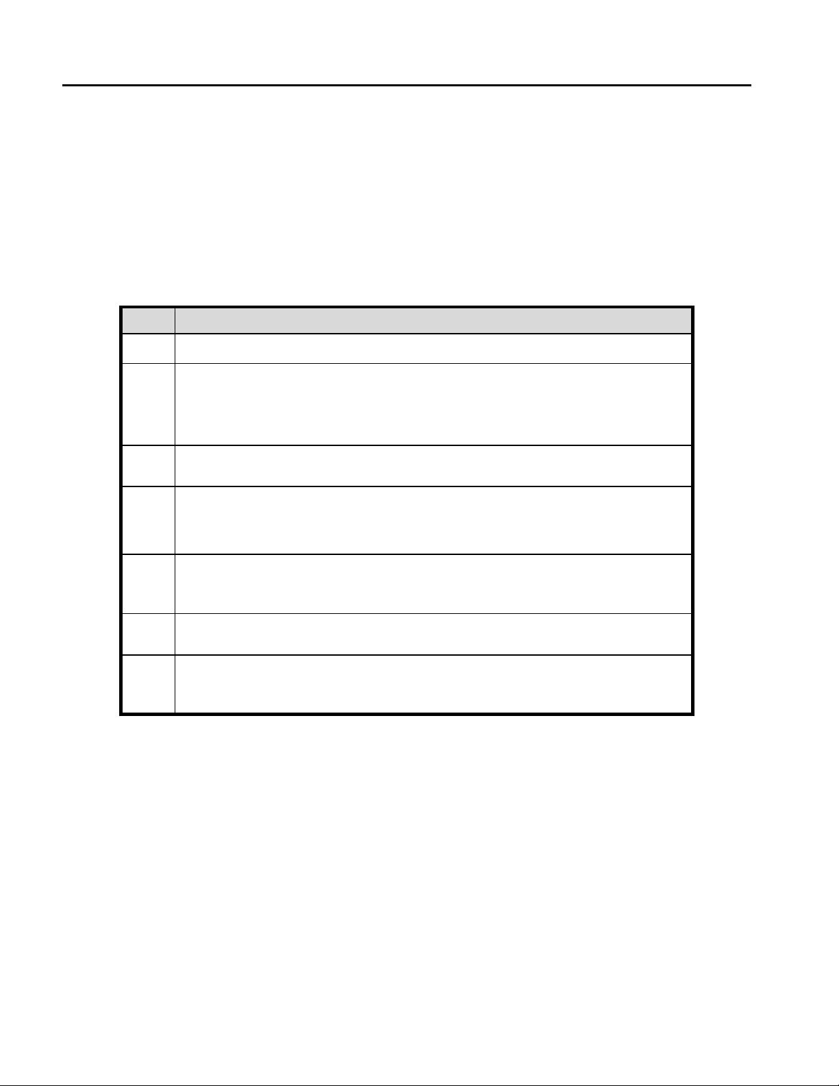
Procedure 3. Making Power Node/30 Connections
STEP ACTION
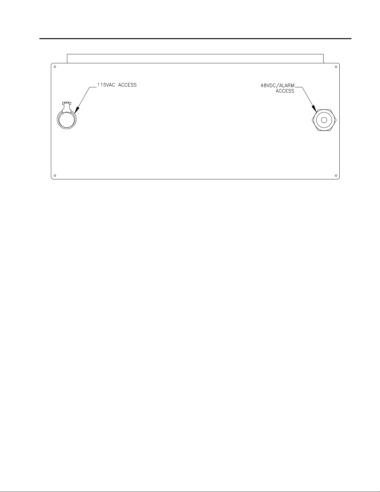
1 Route DC wiring and alarm wiring, if applicable, through the Pulsecom provided
3/4" strain-relief fitting installed in the bottom of the cabinet; see Figure 4
2 Seal the opening after routing the wires from the inside using installer provided
duct seal putty.
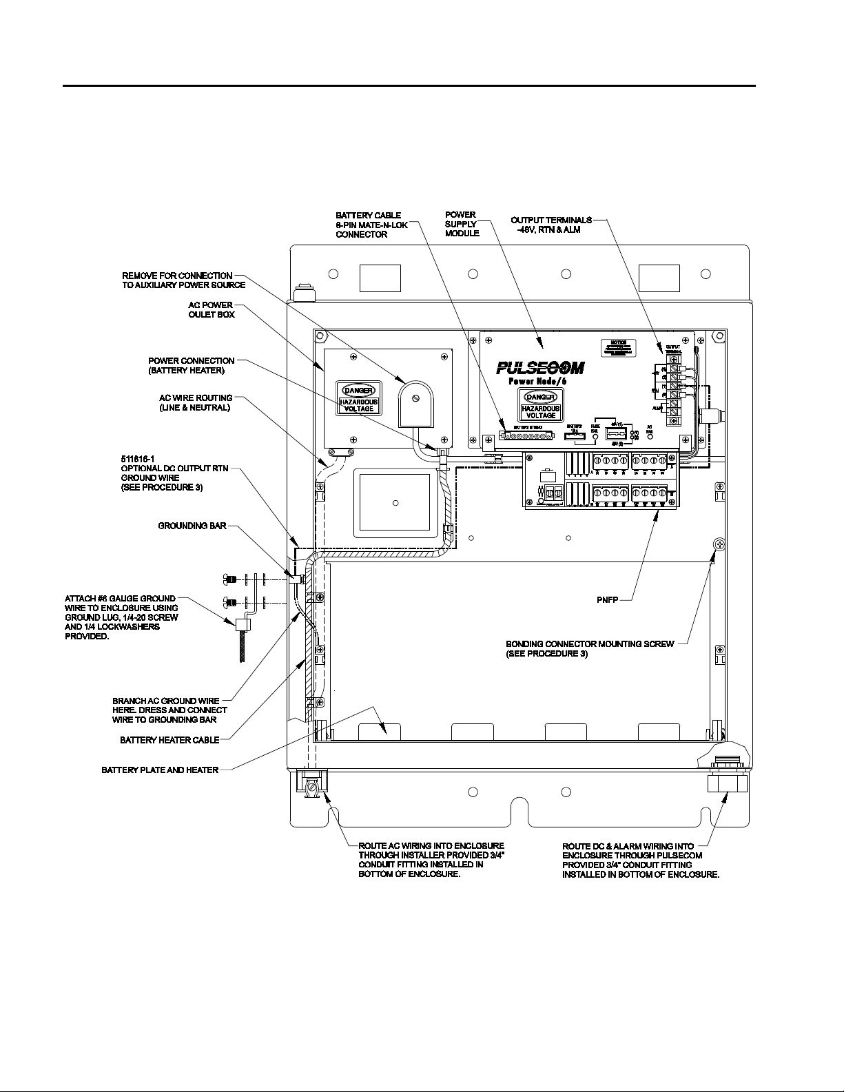
3 If required, locate the supplied 003484-0008 buried service wire bonding
connector in the 511542-1 Accessories Kit. Attach it to the mounting plate by
loosening the bonding connector mounting screw shown in Figure 3 and sliding
the forked tongue of the bonding connector’s mounting bar between the flat washer
and mounting plate. Tighten the screw. Then follow the instructions printed on the
bag that the 003484-0008 came in to attach the buried service wire to the bonding
connector.
4 Connect DC wiring to the –48V (1) and RTN (1) output terminals. Observe
polarity.
NOTE 1: DC load wiring gauge depends upon the distance between the
Power Node/30 and the load. Since a 0.25V drop is allowed between the
power system and the load:
* 14-gauge wire can be used when the distance is 7 feet or less.
* 12-gauge wire must be used when the distance is 8 to 11 feet.
* 10-gauge wire must be used when the distance is 12 to 17 feet.
* 8-gauge wire must be used when the distance is 18 to 25 feet.
The wire insulation type should be THHN or equivalent to provide the
required mechanical protection. Connections should be made with crimp-
on wire terminations applied with the proper tool.
NOTE 2:The Power Node/30 is equipped with a 7.5A output fuse installed
for each of two –48V outputs and one spare 7.5A fuse. If only one output
is utilized, then the unused−48V fuse must remain installed to suppress
the open-fuse alarm function.
CAUTION: Do not exceed the maximum current draw of 6 Amperes.
5 If grounding of the output return is desired, connect the spade lug end of the
supplied 511816-1 DC Output RTN ground cable (yellow/green wire) to either the
RTN (1) or RTN (2) output terminal located on the Power Supply Module. Then
route the optional DC Output RTN ground wire as shown in Figure 3, and connect
the other end to the grounding bar. Secure the wire to the panel using the supplied
cable ties.
6 Connect alarm wiring to the ALM output terminals located on the Power Supply
Module (see Figure 3).
7 Route AC wiring through the installer-provided 3/4" conduit located in the bottom
of the cabinet as shown in Figure 3.
8 Connect third wire ground to the grounding bar located on the inner left-side panel
of the Power Node/30 cabinet. Remove AC outlet box cover. Connect Hot and
Neutral wires to the terminal block as marked. Replace the cover.

Power Node/30
1650, Issue 1, March 2011
11
STEP ACTION
9 If desired, secure AC wiring and DC/Alarm wiring in place using the wire tie-
down points on the inside mounting plate and the tie-wraps supplied in the
511542-1 Accessories Kit; see Figure 3.
10 Remove the BATTERY 10-Ampere fuse from the power supply module; see
Figure 3.
11 Unplug the 8-pin MATE-N-LOK end of the 512516-1 battery cable assembly from
the power supply module; see Figure 3.
12 Screw a threaded rod (packaged with enclosure) into each coupling nut on each
side of the battery tray; see Figure 5.
13 Place batteries on the tray, with the terminals oriented as shown in Figure 6.
14 Any pair of wires in the 512516-1 battery cable assembly can be attached to any
battery. Be careful to follow the color code: Black wire to a negative (–) battery
terminal and Red wire to a positive (+) battery terminal.
•Attach all of the Black wires from the 512516-1 battery connect cable to
the negative (–) battery terminals first.
•Slide the batteries into their final positions.
•Align the holes in the battery hold-down clamp over the threaded rods
installed in Step 12 such that the clamp rests on top of the batteries; see
Figure 6.
•Secure the battery hold-down clamp using the wing nuts provided in the
511542-1 Accessories Kit; see Figure 6.
•Attach all of the Red wires from the 512516-1 battery cable assembly to
the positive (+) battery terminals.
15 Plug the 512516-1 battery cable assembly into the 8-pin MATE-N-LOK connector
on the power supply module.
16 Install the BATTERY 10-Ampere fuse in the power supply module.
17 Verify that the batteries supply power [AC FAIL indicator is flashing and the (1)
and (2) indicators are ON]. The cooling fan will not be running.
18 Apply 115 VAC, 60 Hz power. Verify that the AC FAIL indicator is extinguished
and that the (1) and (2) indicators are ON. The cooling fan will be running.
NOTE
The cabinet is connected to earth ground once AC power has been properly installed.
However, the DC output is isolated from earth ground. If desired, the installer can ground the
output per Procedure 3, Step 5.

Power Node/30
1650, Issue 1, March 2011
12
Figure 5. Power Node/30 Battery Installation – Hardware Details

Power Node/30
1650, Issue 1, March 2011
13
Figure 6. Power Node/30 Battery Installation – Battery Wiring Details
E. Using Auxiliary Power
In the event of an extended AC power outage, the Power Node/30 may be connected to an auxiliary power
source (such as a portable generator). To use an alternate source, disconnect the power supply electrical cord
from the outlet box and connect it to the auxiliary source via a suitably sized 3-conductor outdoor extension
cord.

Power Node/30
1650, Issue 1, March 2011
14
5. SPECIFICATIONS
Table 3 lists the electrical, environmental, and physical characteristics of the Power Node/30. Figure 7 shows
temperature-compensated float voltages.
Table 3. Power Node/30 Specifications
Description Specification
Electrical
Input voltage
a) Nominal
b) Range
115 VAC, 60 Hz
95 to 132 VAC
Input power, maximum (including battery heater) 625 Watts
Output voltage, nominal – 54 VDC at 20°C (68°F)
Battery float voltage, nominal (see Figure 7) – 54.5 VDC at 20°C (68°F)
Ripple, maximum 40 mVrms
Output current, maximum 6 Amperes
Efficiency, minimum 80% full load
Heat dissipation at full load 80 Watts
Line/load regulation (95 to 132 VAC input) 5%, minimum to maximum current
Low voltage disconnect (nominal) – 42.0 VDC
Environmental
Temperature range
a) Operating (outside ambient)
b) Storage
–40° to +46°C(–40° to +115°F)
Relative humidity, no condensation Up to 95%
Physical
Dimensions (height x width x depth)
a) Overall cabinet
b) Cabinet without mounting tabs
20 x 25 x 12 in (50.8 x 63.5 x 30.5 cm)
20 x 20 x 12 in (50.8 x 50.8 x 30.5 cm)
Weight
a) Power Node/30 without mounting hardware
b) Power Node/30UF without mounting hardware
a) PN-POLE-STABILIZER
b) Power Node with batteries and with
PN-POLE-STABILIZER
63 pounds (28.6 kilograms)
64 pounds (29.0 kilograms)
12 pounds (5.4 kilograms)
190 pounds (86.2 kilograms)

Power Node/30
1650, Issue 1, March 2011
15
Figure 7. Power Node/30 – Temperature-Compensated Float Voltage
6. MAINTENANCE
In the event of a malfunction, check the Power Node/30 indicators and Table 4 for possible corrective
actions.
It is recommended that battery performance be checked in accordance with customer’s standard practices. If
such standards are not available, the batteries may be bench-tested by a qualified technician following the
process and parameters outlined in Procedure 4.
Contact Pulsecom Customer Service to order replacement parts. See Procedure 5 for replacement
instructions.

Power Node/30
1650, Issue 1, March 2011
16
Table 4. Power Node/30 Troubleshooting
LED Function Corrective Action
(1)
(Green)
Lights to indicate that – 48 VDC
power is supplied to the (1) output
terminal.
If LED is extinguished:
•Check FUSE FAIL LED.
On: Replace – 48V (1) fuse.
Off: Check – 48V (1) fuse for defects or poor seating.
•Check output voltage by placing probes on – 48V (1) and RTN
(1) terminals.
If Present: Defective LED.
If Not Present with AC On: Defective power supply.
If Not Present with AC Off: Discharged or disconnected battery
string
(2)
(Green)
Lights to indicate that –48 VDC
power is supplied to the (2) output
terminal.
If LED is extinguished:
•Check FUSE FAIL LED.
On: Replace –48V (2) fuse.
Off: Check –48V (2) fuse for defects or poor seating.
•Check output voltage by placing probes on – 48V (2) and RTN
(2) terminals.
If Present: Defective LED.
If Not Present with AC On: Defective power supply.
If Not Present with AC Off: Discharged or disconnected battery
string
AC FAIL
(Flashing
Yellow)
Flashes to indicate AC or charger
failure; system is operating via
batteries.
Extinguishes to indicate that the
charger is working properly.
DANGER: Ensure that AC power
is OFF before removing AC outlet
box cover. Only a licensed electri-
cian or technician formally trained
and approved to work with AC
power circuitry should examine
wiring or perform AC wiring repairs
within the outlet box.
If LED is flashing:
•Check AC service to Power Node/30.
If Not Present: Check utility primary breaker/fuse or contact
utility.
If Present: Proceed to next bullet.
•Check voltage at outlet box in Power Node/30.
If Not Present: Check wiring to and inside outlet box for open
circuit.
If Present: Proceed to next bullet.
•Check power cord to power supply for secure contact.
Check for voltage at the connector end of cord.
If Not Present: Replace power cord.
If Present: Proceed to next bullet.
•Power supply module defective; replace.
FUSE FAIL
(Red)
Lights to indicate open battery fuse
(batteries are disconnected from
the load) or open output fuse.
If LED is illuminated:
•Check all fuses.
•Replace any open fuses.
Indicator Function Corrective Action
ALM
(OUTPUT
TERMINAL)
Contact closure to indicate loss of
AC power, loss of output power,
open battery fuse, open/missing
output fuse(s), or any combination
thereof.
If contact closure indication is present:
•Check all functions and take corrective action for anomalies.
•If all functions are normal, remove alarm connections from
power supply terminal block.
•Check alarm terminals for low impedance.
If Not Present: Check alarm wiring for shorts.
If Present: Power supply module defective; replace.

Power Node/30
1650, Issue 1, March 2011
17
Procedure 4. Testing the Batteries
A. Lead-Acid Battery Preparation
STEP ACTION
1 NOTE: Since batteries can be in widely varying states of charge, a
conditioning charge is the best way to make certain that the battery is
tested in a fully charged state.
Charge the battery on a well regulated constant voltage set for 13.5 to 13.8 VDC.
The charger must be capable of delivering at least 3.0 Amperes of charge current.
2 Charge the battery for 16 hours minimum.
3 Rest the battery for a period of 12 hours before any testing.
4 The battery terminal voltage, after the rest period, should be approximately 12.72
VDC to 13.02 VDC.
•If the battery falls within the terminal voltage parameters above, there is a high
probability that it is good and discharge testing is optional.
•If the battery terminal voltage is between 12.40 and 12.62 VDC, then the
discharge test is recommended.
•If the terminal voltage is below 12.40 VDC after proper charging, there is a
high probability that the battery has a low discharge capacity and short life
expectancy. It is recommended, in this case, that the battery be replaced.
B. Lead-Acid Battery Discharge Test
STEP ACTION
1 NOTE 1: For optimum performance or acceptance testing, a half-hour
capacity test is sufficient to determine the status of the battery.
NOTE 2: The half-hour discharge current rate for each SBS40 (12V/38AH)
battery is 51 Amperes.
NOTE 3: Use only approved battery discharge equipment.
Discharge the battery at the given rate to an end terminal voltage of 10.2 VDC.
2 The battery should run for at least 30 minutes before it reaches the end voltage.
3 If the battery does not deliver at least 30 minutes of discharge time, it should be
recharged and retested.
4 If the battery still does not meet the requirements of the 30-minute test, it should be
replaced.

Power Node/30
1650, Issue 1, March 2011
18
Procedure 5. Replacing Power Node/30 Parts
STEP PART ACTION
1 Fuse Cap
(003344-0001) DANGER: Use care when working around -48 VDC. Remove metal
jewelry and avoid touching bare power supply leads. Remove AC
power and batteries before making any changes to wiring or
electrical parts.
A) Grasp fuse cap; remove cap and fuse from holder.
B) Remove fuse cap from fuse.
2 10-Ampere
Fuse
(003337-1000)
A) Complete Step 1.
B) Fasten cap on new fuse.
C) Re-install cap and fuse in holder.
3 7.5-Ampere Fuse
(003343-0750) A) Complete Step 1.
B) Fasten cap on new fuse.
C) Re-install cap and fuse in holder.
4 AC Power Cord
(511559-1) A) Cut cable ties holding cord to panel.
B) Unplug cord from outlet box and power supply.
C) Plug replacement cord into outlet box and power supply.
D) Secure cord to panel with cable ties.
5 Battery Harness
(512516-1) A) Remove the battery fuse.
B) Remove the battery hold-down clamp.
C) Disconnect harness from power supply by squeezing 8-pin connector
locking ears and pulling outward.
DANGER: Batteries contain explosive gas. Keep ignition sources
such as flames, cigarettes, and sparks away. Remove rings,
watches, and other jewelry while handling or making connections.
Follow all applicable safety precautions.
D) Disconnect red and black wire pairs from each battery.
E) To install (new) battery harness, reconnect a red and black wire pair to
each battery: Black wire to – terminal and Red wire to + terminal. Any
of the four pairs may be connected to any of the four batteries.
F) After all connections have been made to the batteries, push the battery
harness 8-pin connector into the power supply battery string connector
until it “clicks” into place.
G) Reinstall the battery hold-down clamp to secure batteries in position.
Do not pinch or trap battery cables between clamp and batteries.
H) Reinstall battery fuse.

Power Node/30
1650, Issue 1, March 2011
19
Procedure 5. Replacing Power Node/30 Parts (Continued)
STEP PART ACTION
6 12V/38AH
Battery,
EnerSys
PowerSafe
SBS40
(Customer-supplied)
Four required
CAUTION: Do not use metal tools. Install lead-acid batteries only.
A) Complete Steps 5A through 5D.
B) Remove (old) batteries from enclosure.
C) Place new batteries in the enclosure. If the batteries have been in use
for several months, it is recommended that all four batteries be replaced
at the same time with new fully charged batteries; never mix new
batteries with old batteries.
D) Complete Steps 5F through 5H.
7 Power Supply,
6-amperes
(511247-1)
A) Complete Step 4B.
B) Complete Step 5C.
C) Remove all wires connected to the power supply output terminal block.
D) Loosen and remove the four #6–32 screws securing the power supply
mounting plate.
E) Remove the power supply from the enclosure.
F) Install the replacement power supply by reversing the process in Steps
7E through 7A.
8 Door Ground
Cable
(510624-1)
Remove or install door ground cable with a 7/16" hex nut driver.
9 #6 AWG
Ground Lug
(003484-0007)
Not applicable.
10 Battery Hold
Down Clamp
(512067-1)
Not applicable.
11 Wing Nut
(004250-0003)
Two Required
Not applicable.
12 Door Key
(005000-0088) Not applicable.
13 Manual
(IN1650) Not applicable.

Power Node/30
1650, Issue 1, March 2011
20
7. CUSTOMER SERVICE
Direct questions concerning the operation of the Power Node/30 to Pulsecom Technical Support. Obtain repair
services of the 511247-1 Power Supply Module by returning the defective unit to the Pulsecom Repair
Pulse Communications Incorporated Customer Service
2900 Towerview Road, Suite 100 1-800-381-1997
Herndon, Virginia 20171-3286 custservice@pulse.com
400 E. Wyomissing Avenue Technical Support
Mohnton, Pennsylvania 19540 1-800-841-1005
Table of contents
Other PULSE+ Power Supply manuals