PUMATRONIX ITSCAM FF600 Product manual

Illuminator 1
Ethernet Cable
Illuminator 2
Power Cable
1. Select an existing pole or gantry that allows positioning the ITSCAM FF
600 preferably centered on the track, with the objective of capturing images
of one or two lanes of the track, considering the linear distance between the
equipment and the image center:
2. Pass the connection cables through the PG9 cable glands, considering
the preferred usage of each:
3. Tighten the cable gland until the cable is completely fixed.
4. Go to the available interfaces on the Connections Board or on the back
panel of the ITSCAM 600 device to connect the cables:
5. Use the connectors available on the back panel of the ITSCAM
600 device:
6. Make the RS-485 and RS-232 data connections with the Connections
Board considering the connectors interfaces and their colors:
POSITIONING ITSCAM FF 600 AT VIA
CONNECTING TO ITSCAM FF 600
When using an Illuminator in conjunction with ITSCAM
FF 600, check in the product specifications which
minimum and maximum distance must be observed in
relation to the position of the object to be illuminated.
The SD card must always be plugged in for the correct
functioning of ITSCAMPRO Móvel plugin .
USB 2.0
SD Card
4G/3G/2G Antenna
MOV Antenna
SIM Card
Ethernet 2GB
Wi-fi Antenna
GPS Antenna
ITSCAM 600
back panel
Connections
Board
Side positioning
to the track
Lane 1
Lane 2
Image Center
ITSCAM FF 600
D minimum
10 meters
D maximum
17 meters
d d
d
1/4
26/04/2022
Revision 1.0
GUIDE TO INSTALLATION
AND MAINTENANCE
485_B
232_TX
P9
P11
485_GND
232_GND
485_A
232_RX

NETWORK INTERFACE PARAMETERIZATION
8. Connect the ITSCAM FF 600 to an auxiliary device disconnected from the
local network in which the equipment will be installed, using an Ethernet
cable:
Ethernet
IP
192.168.0.254
Username
Admin
Password
1234
Values that cause conflict
IP Adress
Network Mask
192.168.254.x
255.255.255.0
192.168.x.x
255.255.0.0
192.x.x.x
255.0.0.0
0.0.0.0
9.Access the ITSCAM FF 600 interface using a Google Chrome browser
(from version 85 or higher) with the default factory data:
10. Go to the menu Equipment > Network on the Ethernet tab.
11. Enter a network ID in the Hostname field.
12. Select the IPv4 connection type to Enabled (manual).
13. Enter the Primary Interface (ETH-1) data, changing the default values
of IP address 192.168.0.254 and subnet mask 255.255.255.0 to values other
than those that might cause conflict on the existing network:
T h e m a i n t e n a n c e I P of t h e ITSCAM F F 600
(192.168.254.254) is used to recover the connection in
extraordinary situations of loss of the primary IP. For
this reason, when manually configuring the equipment
network interface (Ethernet or Wi-Fi), different values from the
maintenance IP must be applied.
7. Perform power connections to the Connections Board, considering the
P4 connector interfaces and their respective colors:
16.Repeat steps 8 to 15 if there is a connection loss or IP address conflict.
17. Log on with the maintenance IP address 192.168.254.254, just in case
of any network conflicts.
15. Disconnect the ITSCAM FF 600 from the auxiliary device and connect
the equipment to the network of the final installation.
14. Confirm the changes by clicking on the Apply button at the top of the of
the page:
ACCESS POINT SETUP
25. Select the Access Point (AP) operating mode only when the device is to
be used as an access point to an available WiFi network.
26. Enter the identification data (SSID), the Country, the Channel and the
Authentication protocol that will be applied when distributing the WiFi
connection.
27. Enter the IP Address and Subnet Mask of the DHCP Server to
determine the address range for the devices that will connect to the access
point.
19. Go to menu Equipment > Network at Wi-Fi tab.
20. Choose the Station (STA) Operation Mode for connecting to an existing
Wi-Fi network.
21. Click on the SSID field and the nearby Wi-Fi networks available for
connection are listed for selection.
22. Select the Authentication Protocol a ser utilizado: Open (sem
autenticação), WPA, WPA2, WPA & WPA2.
23. Enter the password to access the selected Wi-Fi network.
24. Click on the Apply button at the top of the page when validating the
entered data.
WI- FI NETWORK CONFIGURATION (IoT
DEVICES)
18. Access the device's web interface with data recorded in the NETWORK
INTERFACE PARAMETERIZATION.
The Wi-Fi, 4G and 3G network interfaces are disabled in
the equipment's factory default settings.
Use a different IP address from the one used to access
the ITSCAM FF 600 device in order to avoid conflicts and
malfunctioning of the data network.
T h e m a i n t e n a n c e I P of t h e ITSCAM F F 6 0 0
(192.168.254.254) is used to recover the connection in
extraordinary situations of loss of the primary IP. For
this reason, when manually configuring the equipment
network interface (Ethernet or Wi-Fi), different values from the
maintenance IP must be applied.
2/4
26/04/2022
Revision 1.0
NGNDF
P10 P8P7 P6
P4P5
P9
P11

FRAMEWORK SETTINGS
43. Adjust the desired zoom and focus position, until the license plate is
readable and in capture condition (height approximately 20 pixels).
40. Access the device's web interface with data recorded in the NETWORK
INTERFACE PARAMETERIZATION.
41. Check at the home screen the available zoom and focus controls in the
Live feed window (of adjustable size), in the scroll bars on the left. If it is not
enabled, select from the window's settings:
42. Increase or decrease the Live feed window to facilitate zoom and focus
adjustment.
44. Repeat steps 38 to 43 until the image of the plate is obtained with
optimal framing and character clarity.
ITSLUX POSITIONING
38. Move the equipment's base articulation to tilt vertically or rotate
horizontally by loosening the respective screws:
33. Perform the fixing of the ITSCAM FF 600, with cables passed and
attached to the cable glands, on the Pole Bracket using the 4 screws M6 x 25.
34. Provide stainless steel clamps with enough length and appropriate to
the diameter of the installation pole.
FASTENING OF ITSCAM FF 600 ON POLE
Use stainless
steel clamps
4 screws M6
stainless steel
Pole Bracket
37. Install the ITSCAM FF 600 at a slight angle, so that the license plate
appears in the image aligned with the horizontal plane.
35. Place the ITSCAM FF 600 + Pole Bracket assembly over the via,
respecting the minimum height limits specified for the site and the minimum
and maximum distances indicated in POSITIONING ITSCAM FF 600 AT VIA.
39. Tilt the equipment on the base until the best framing fit, considering
the maximum angle limit of 45° for vertical tilt. Greater angles of vertical
inclination generate significant deformations in the generated images.
36. Avoid blocking out parts of the image by objects such as trees or
vehicles from other tracks.
45°
Horizontal
Rotation
Vertical
Inclination
When using an Illuminator in conjunction with ITSCAM
FF 600, check in the product specifications which
minimum and maximum distance must be observed in
relation to the position of the object to be illuminated.
45. Fasten 1 or 2 illuminators optionally to the same pole and just below
the ITSCAM FF 600 device, keeping the minimum distance of 50 centimeters.
50 cm
3G OR 4G MOBILE NETWORK SETUP
29. Access the device's web interface with data recorded in the NETWORK
INTERFACE PARAMETERIZATION.
The Wi-Fi, 4G and 3G network interfaces are disabled in
the equipment's factory default settings.
30. Go to menu Equipment > Network on the Mobile tab.
31. Click on Enabled and the configuration fields will be displayed.
32. . Click on Apply to save the network settings.
*Users of the Claro operator must manually fill in the APN
configuration fields with data:
APN: claro.com.br
User: claro
Password: claro
*For operators with a personalized APN, User and Password, the fields
must be filled in for the 3G or 4G connection to work.
3/4
26/04/2022
Revision 1.0

FIRMWARE UPGRADING
SITUATIONS WHERE PRODUCT LOSES
WARRANTY
WARRANTY TERM
PRIVACY POLICY
Pumatronix warrants the product against any defect in material or
manufacturing process for a period of 1 year from the invoice issue
date, provided that, at the discretion of its authorized technicians, a
problem is found under normal use conditions.
The replacement of defective parts and the execution of services
resulting from this warranty will only be carried out at the Pumatronix
Authorized Technical Assistance or a third party expressly indicated by
it, where the product must be delivered for repair.
This warranty will only be valid if the product is accompanied by the
Maintenance Form duly filled out and without erasures and followed by
the Invoice.
In compliance with the General Law on Data Protection (LGPD) - Law
No. 13,709, of August 14, 2018, this product has programmable
functions for capturing and processing images that may infringe the
LGPD when used, in conjunction with other equipment, to capture
personal data.
Pumatronix is not responsible for the purposes, use and treatment of
the images captured, and the control of the information and forms of
operation of the product are the sole decision of the user or acquirer of
the product. is the sole decision of the user or acquirer of the product.
1) Usage of software/hardware not compatible with the specifications
in the Manual;
2) Connecting the product to the power grid outside the standards
established in the product manual and installations that present
excessive voltage variation;
3) Liquid infiltration resulting from the product opening/closing;
4) Natural damage (electric discharge, flood, sea fog, excessive
exposure to climate variations, among other factors) or excessive
exposure to heat (beyond the limits established in the manual);
5) Usage of the product in environments that are susceptible to
corrosive gases, excessive humidity and/or dust;
6) To present signs of security seals tampering;
7) Show signs of opening and modification made by the customer in
parts of the product not authorized by Pumatronix;
8) Damage caused by accidents/falls/vandalism;
9) To present adulterated and/or removed serial number;
10) Damages resulting from transportation and packaging of the
product by the customer in conditions incompatible with it;
11) Misuse and in disagreement with the Instruction Manual.
Follow the security measures during the upgrade process:
* Keep the ITSCAM FF 600 device inactivated during the upgrade
process, guaranteeing that it is not requested by any service or
other equipment on network in which it is installed;
* Keep the ITSCAM FF 600 device powered on at all times during
the upgrade process, making sure to take the necessary steps to
prevent it from being restarted or switched off.
* Request the firmware file by filling out the form available in the Technical
Support menu at Pumatronix website.
* Access in the Product Manual the step-by-step installation of firmware
updates and of the ITSCAMPRO Móvel plugin.
* For additional information, access the
product manual at www.pumatronix.com.br.
TECHNICAL SUPPORT
+55 41 3016 – 3173 | suporte@pumatronix.com
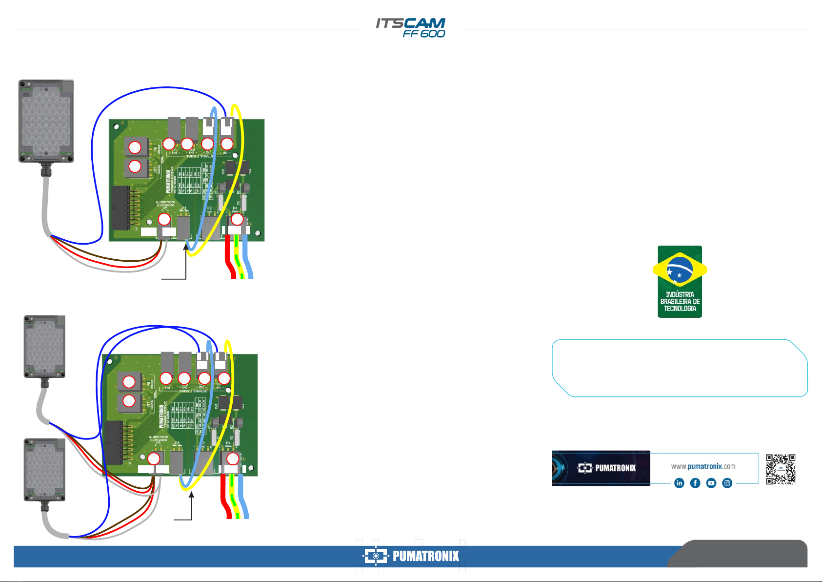
47. Connect the wires of the 2 ITSLUX cables following the colors and
connectors indicated on the Connections Board:
Existing
connections
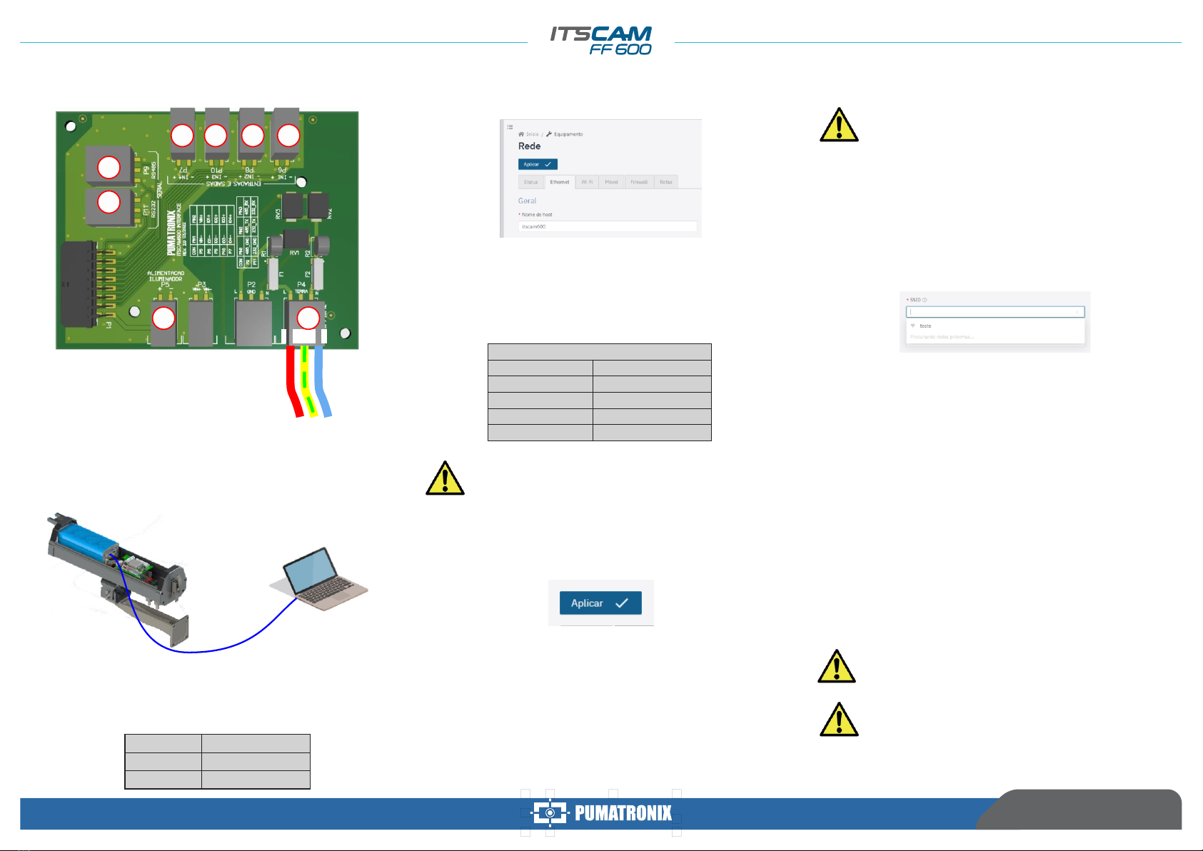
46. Connect the cable wires of 1 ITSLUX following the colors and
connectors indicated on the Connections Board:
ITSLUX ELECTRICAL CONNECTIONS
4/4
26/04/2022
Revision 1.0
Movement in Focus.
NGNDF
-- ++
P10 P8P7 P6
P4
P5
P9
P11
IO1IO2
VIN-
VIN+
Power cable
-- ++
P10 P8P7 P6
P4
P5
P9
P11
N
IO1IO2
GNDVIN-VIN+ F
Existing
connections Power cable
Other manuals for ITSCAM FF600
1
Other PUMATRONIX Security Camera manuals