Physical size .................................. 16.75W x 1.75H x 14D (inches)
426W x 44H x 356D (mm)
Unit stands 1 RU high and may be
mounted in a standard 19” rack.
5
8100 Input Signal Loss Budget Max. Distance 8100 Part Number
Provided By: in dB: in km: Configuration for “y”
P/N: Flex System
part suffix
-1 0-18 2 8
-3 0-1 0.3 3
-7 2-18 40 3
-9 0-17 55 3
Loss Budgets and Maximum Transmission Distance
The following charts show loss budgets and maximum transmission
distances for all units compatible with the 8100 Series. Products not
included on the input and/or output chart do not function with the 8100
O.D.A.. Note that some systems operating at the highest wavelength
are compatible with the 8100’s input but not with its output.
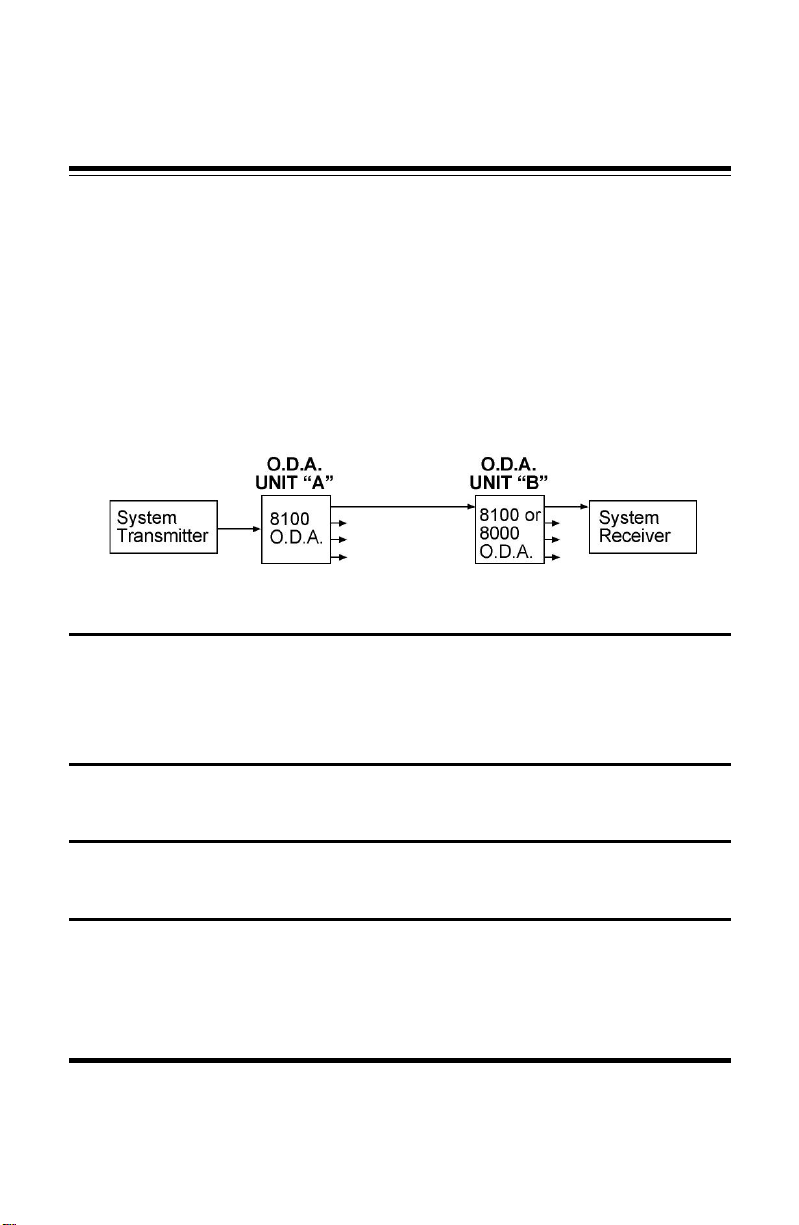
For loss budgets resulting from the cascading of two or more O.D.As
together, refer to the chart beginning on page 8.
CAUTION! Some versions of the Pure Digital Fiberlink 8100 Series O.D.A. contain a
solid state Laser Diode located within the optical connector. This device emits
invisibleinfraredelectromagneticradiationwhichcanbe harmfulto humaneyes.The
radiation from this optical connector, if viewed at close range without a fiber optic
cable connected to the optical connector, may be of sufficient intensity to cause
instantaneousdamagetothe retina of theeye.Direct viewing of thisradiationshould
be avoided at all times.
Troubleshooting
Multimode fiber optic cable contains an optical fiber with a light
carrying “core” that is only .0025 inches (62.5 microns) in diameter.
Single mode fiber optic cable has an even smaller “core,” only .00032
to .0004 inches (8-10 microns). This is smaller than a human hair! As a
result, any minute particles of dirt or dust can easily block the fiber
from accepting or radiating light. To prevent this from happening, al-
ways use the dust caps provided with all optical connectors whenever
they are exposed to air. Also, it is a good idea to gently clean the tip of
an optical connector with a lint-free cloth moistened with alcohol when-
ever dust is suspected.
The status of any of the indicator LEDs should provide the first clue
as to the origin of any operation failure. If, on the O.D.A., the SIGNAL
and LOCK LEDs are off, it usually means that the fiber is broken or has
too much attenuation.
Refer to the troubleshooting section of the manuals that came with
your transmitter and receiver units for additional tips specific to that
particular system
If, after reviewing the above possibilities, the system is still not oper-
ating, please contact the Customer Service Department for further as-
sistance.
12