PureAudio Project Tower15TB User manual

Congratulations!
Thank you for your purchase of the new PureAudioProject TB tower speakers & baffles.
We at PureAudioProject expect you to have countless hours of musical enjoyment.
Please read these instructions carefully before operating your set. Retain for future reference.
Warnings
Using tools can be dangerous take care!
To reduce the risk of fire or electric shock, do not expose this product to rain or moisture.
The assembled baffles with the speakers are heavy, be careful!
Parts list for TB HW Tower kit (exc. Legs)
1. 10 metal side struts (regular).
2. 2 metal side struts for XOs.
3. 24 furniture bolts M6*80 (with flat heads for baffles).
4. 24 rubber decouplers.
5. 24 furniture bolts M6*60 (with flat heads for back leg).
6. 24 Allen bolts M6*60(with deep head for sides).
7. 72 thumb nuts M6.
8. 6 spikes.
9. 6 nuts for spikes.
10. 6 felt pads for spikes.
11. 16 M5*40 bolts (for TB).
12. 16 M5 thumb nuts.
13. 32 screws (wood for mounting Alpha drivers).
14. 2 logos.
15. 8 bolts M5*20 (for XOs).
16. 8 nuts M5 (for XOs).
17. 8 M5 thumb nuts (for XOs).
18. 6 cables (2 short,2 medium,2 long).

Tools
Allen # M6, M5 keys
Philips screwdriver.
Spanner # M8.
Assembly instructions
1. Take a minute to look at the pictures at end of document and other pictures on our web
site, to understand in depth the construction.
2. Lay out all the parts, and familiarize yourself with all parts as listed above .
3. Place 1 back leg (4X7cm) lying on a carpet, or covered floor.
4. Take 5 regular metal struts and 1 metal strut for XO.
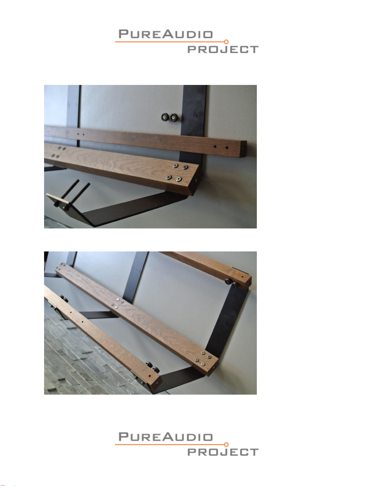
5. Connect the shortet angle of 5 metal struts to the back leg (top, mid & bottom), using 2
Allen bolts M6X60 (the bolts with the round head) per strut, inserting from the wood side,
and lightly tightening with thumb nuts (please note the struts are on the outer side of the
leg) (see picture # 3).
6. Do not connect the strut for the XO, Please note, the strut for the XO is in the lower
position (near the metal inset for the spike), on the side facing the amp with the hole for the
binding posts facing the back leg.
7. Repeat on the other side of the leg in the opposite direction (see picture #3).
8. Connect the front legs (pictures #4-5) all 5 metal struts to the using the M6X60 bolts with a
deep head, please note, the bolts are inserted from the outside, i.e. thru the metal brace,
and then the wooden leg and lightly tightening with thumb nuts M6,
9. Tighten all thumb nuts if needed you can use an allen key.
10. Repeat steps 3-9 on the other legs.
11. Put locking nut on thread of spikes.
12. Insert spikes into inserts at bottom of legs (leave the front spikes about 1.5cm longer then
the back one, to give the cube a tilt) tighten the locking nut to the insert (do no not over
tighten).
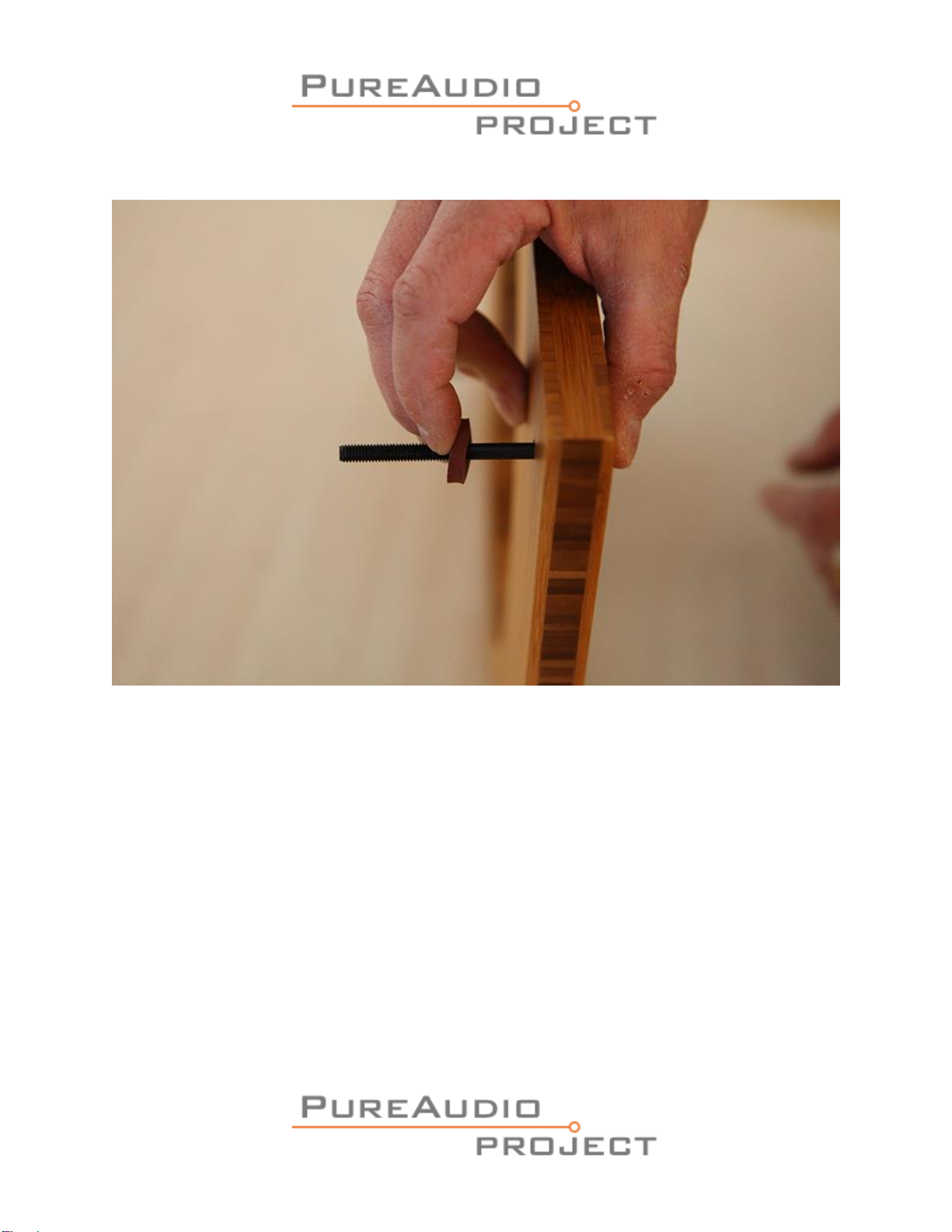
13. Insert 4 M6*80 furniture bolts (the bolts with the flat head) into front of baffle, insert a
rubber decoupler on each bolt (at the back of the baffle) (see picture # 6).
14. Repeat for all the baffles.
15. Lay out the baffles face down, using the numbers on the reverse side to keep the natural
grain of the wood.
16. Place the Eminance speakers face down on the baffles, aligning the holes in the basket with
the pre drilled guide holes in the baffles.

17. Insert the screws (wood for mounting Alphas) thru the holes into the guide holes, and
tighten with a screwdriver. (warning, use screws not longer than 20mm!!).
18. Stand the feet on the spikes.
19. Mount the baffles on the front feet (keeping the numbers in sequence from top to bottom),
using the bolts pre inserted in the baffles and tighten with thumb nuts (see picture # 7).
20. Insert the smaller baffles into the feet between the two larger baffles, tighten with thumb
nuts.
21. Mount the TB speakers from the front thru the cutout, inserting bolts (M5) thru the speaker
and the pre-drilled holes (be careful of dropping the speaker).
22. Tighten the bolts with the thumb nuts (M5).
23. Look at pictures 8,9,10.
24. Please note, the markings on the XOs are on the opposite side of the screw for connecting
the speaker cables.
25. Connect the cables to the screws on the XOs (the shortest and longest cables go to the
Alpha (base)woofers).
26. Please make sure the red goes to the + sign as seen in picture 8.
27. Insert 4 M5*20 bolts thru the XO brace (from the outside) and tighten the bolts with the
nuts (picture 10).
28. Mount the XO from the inside with the binding posts going thru the brace (picture 9).
29. Tighten the XO with the M5 thumb nuts (picture 10).
30. Repeat for the other XO on the other speaker.
31. Connect XO braces to the legs in the “empty”space with the binding posts closest to the
rear leg using M6 bolts and thumb nuts (same as regular brace).
32. Connect the speaker cables to the speakers(short and long to the Alphas, Mid to the TB in
the middle), making sure the red cable goes to the + on the speakers.
33. Fix the logos on bottom of speakers using the tape affixed to the logos.
Now is the time to connect the Amps.
Congratulations!
You have finished assembling the speakers.

Picture # 1

picture # 2

Picture #3

Picture #4
Picture #5

picture # 6

picture # 7

Pictures #8

Picture #9

Picture #10
Table of contents