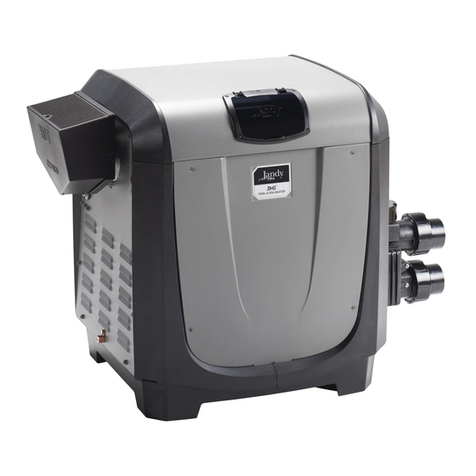
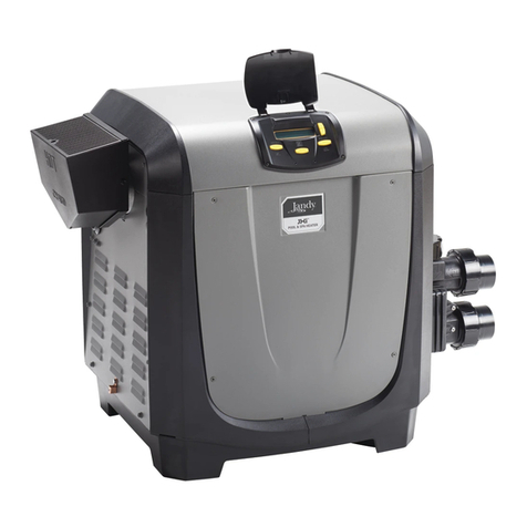
Purex Pool Equipment Tropic Isle C120 User manual

TROPICISLE
POOL
and
SPA
HEATER
INSTALLATION&OPERATION
MANUAL
FORYOUR
SAFETY
- READ
BEFORE
OPERATING
Warning: lf
you
donottollowthese
instructionsexactly,
afireorexploqion
may
result,causing
property
damage,
personal
injuryor
lossoflife.
WARNING:
lmproperinstallation,adjustment,alteration,serviceormaintenance
cancauseinjuryor
property
damage.
Refer
tothismanual.Forassistanc€oradditional
information,-consult
aqualified
installer,serviceagencyor
the
gas
supplier.
FOR
YOUR
SAFETY
WHATTODOIF
YOUSMELLGAS
. Donottrytolightanyappliance.
. Donottouchanyelectricalswitch;donolus€any
phone
inyour
building.
. lmmediatelycall
yourgas
supplierfromaneighbor's
phone.
Followthe
gaS
supplier's
instructions.
. lfyou
cannolreach
yourgas
supplier,callthefiredepartment.
Donotstoreoruse
gasoline
orotherllammablevaporsandliquidsinthevicinityofthis
oranyotherappliance.
HydrolochChemicalCorporation,Cityof Industry

INDEX
Index.
..
NoticeoflmDortance 4,5
Lighting
Operation
llDHeater
Millivolt
Heater
Temperature
Control
....
Single
Temperature
Control
System
Dual
Temperature
ControlSystem
PowerSwitch
Warning
Selector
Dials
Stopper
Thermostat
Knob
Safety
Rules
forSpa
andHot
Tub
Function
lndicatorLight
PowerLight
PressureLight
Heat
Lightand
Hi-LimitLight
Specifications
Chemical
Balance
Pooland
SpaWater
WhatChlorine
Does
What
isChlorine
Residual
Control
pH
Alkalinity
High-Low
WalerConnections
.....
Plumbing
FlangeCoupling
Manual
By"Pass
Circulation
PumD
Below
Pool
lnstallataon
Recommend
FlowRate
9,10
GasConnections.......
Gas
Line
'10
't1
Testing
Regulated
Ventilation Manifold
Pressure
Outdoor
Installalion
lndoorlnstallation
Electrical
Electrical
Wiring
torIntermittent
lgnition
(llD)
Models
lnstallation
Instruction
of Remole
Switch
DualTerm
llD
Electrical
wiring
forMillivolt
Models
Typical
TimeDelay
Clock
(Fireman
Switch)
Maintenance
Maintenance
Instructions
Relief
Valve
Spring
andFallOperation
Winter
Operation
Trouble
Shooting
Exoloded
View
Pa(s
List
12,13,14
15
15
to
'17
18
Control
PanelExoloded
View 19
Notes
Warranty
2
20

TROPICISLEg
POOL
AND
SPA
HEATER
Congratulation5
onyourpurchase
of aTropicIsle
Heatingsystem.
Properin-
stallation
and serviceof your new heatingsystemand correctchemical
maintenanceof the
waterwillensure
years
of enjoyment.
NOTICE
OF
IMPORTANCE
...
...For
installerand operatorof the "Tropic
Isle" pool and spa Heater.
The
manufacturer's
warranty
will not be acceptedas valid
it, tor any
reason,the
heater
isimproperlyinstalled
and/oroperated.
Besure
tofollowthe
instructions
set
forth
in
this
manual.
Theinstallation
mustconform
with localcodes
or, in the absence
of local
codes,
withthe
latest
National
FuelGas
Code,
ANSI2223.1
FOR
YOURSAFETY
-READ
BEFOREOPERATING
WARNING:
lFYOUDO
NOTFOLLOW
THESE
INSTRUCTIONS
EXACTLY,
A FIREOR
EXPLOSIONMAY
RESULT.CAUSING
PROPERTY
DAMAGE,
PERSONAL
INJURYOR
LOSSOF
LIFE.
MEMBER
-
-tgtna

LIGHTING'OPERATION
FOR
YOURSAFETY
READBEFORELIGHTING
IID IIEATERS
WARNING:
lf you
donotfollow
these
instructions
exactly,
a fire
or
explosion
mayresultcausing
property
damage,
personal
iniuryorloss
ti
c.
A.
B.
Thisappliance
isequipped
withanignitiondevice
whichautomatically
lightslhe pilot.
Donottryto
lightthe
pilot
by
hand.
BEFORE
OPERATINGsmell all aroundthe ap-
pliance
area
forgas.
B€sureto smell
nextto lhe
tloorbecausesome
gas
isheavierthanairand
will
settleonlhefloor.
WHATTODO
IFYOUSMELLGAS
. Donottrytolightanyappliance.
. Donottouchanyelectricswilch;
do
nol
use
any
phone
in
your
building.
. lmmediatelycall
your
gas
supplier
froma
neighbor's
phone.
Followthe
gas
supplier's
inslructions.
. lf you
cannot
reach
yourgas
supplier,
callthe
tire
departmeq!.
Use
only
your
hand
lo push
in
orturn
the
gas
con'
trol
knob.Neverusetools.
ltthe
knobwillnot
push
in or turn by hand,don'l try to repairit, call a
qualified
service
technician.
Force
or attempted
repairmay
resultina fireorexplosion.
Do not use this appliance
il any part has been
underwater.
lmmediately
call a qualitied
service
technician
to inspecttheappliance
andto replace
any
part
ofthecontrol
system
andany
gas
control
which
hasbeenunder
water.
D,
OPERATING
INSTRUCTIONS
above.
2.Selthethermostat
to lowestsetting.
3.Turn
otf allelectric
power
to theappliance.
4.Thisappliance
isequipped
wilhanignitiondevice
which
automatically
lightsthe
pilol.
Donottryto
lighlthe
pilot
byhand.
5.Remove
controlaccess
panel.
6. Push in gas control knob slightly and turn
clockwise
^ to"OFF."
NOTE:Knobcannotbe lurnedto "OFF" unlesi
knob
ispushed
inslightly.
Do
notlorce.
7.Wait f
ive
(5)
minutesto clear
out anygas.
lf you
then
smell
gas,
STOP!
Follow
"B" inthesafety
in-
tormationabove.
lf you
don'tsmell
gas,goto next
steo.
8.Turnknobongas
control
counter-clockwise
t-\
to "ON".
L Replace
controlaccess
panel.
10.Turnonall
electric
power
totheappliance.
11.
Setthermostat
todesired
setting.
'12.
lf
the
appliance
willnotoperate,
followtheinstruc-
tions
"To
TurnOffGas
ToAppliance"
andcall
your
service
lechnicianorgas
supplier.
GAS CONINOL
'oN_postltoN
fr:,
)
Fig.2
TOTURNOFFGAS
TO
APPLIANCE
1.
2. Sel
thethermostat
to lowestsetting.
Turn off all electric power to the appliance
if
service
is to beperformed.
Removeconlrol
access
Panel.
Push in gas conlrol knob slightly and
clockwise,,--\ to "OFF."
Do
notforce.
Replacecontrol
access
Panel.
4.
.t.
lurn

LIGHTINGINSTRUCTIONS
FORYOURSAFETY
READBEFORE
LIGHTING
TILLIYOLT IIEATERS
WARNING:lf you
donot
follow
theseinstructionsexactly,afire
or
explosionmayresultcausing
property
damage,
personal
injuryorloss
c.
A.
B.
Thisappliancehasa
pilot
whichmustbelighledby
hand.When
lighting
the
pilot,
followtheseinstruc-
tionsexactly.
BEFORELIGHTINGsmellallaroundtheappliance
area
tor gas.Be suretd smellnextto the floor
because
some
gas
isheavierthanairandwillsettle
onthefloor.
WHATTODOIFYOUSMELLGAS
. Donottrytolightanyappliance.
. Donot
louchany
electricswitch;
do
not
useany
phone
in
your
building.
. lmmediately
call
your
gas
supplier
from
a
neighbor's
phone.
Followthe
gas
supplier's
instructions.
. lf you
cannotreach
yourgas
supplier,callthe
fire
department.
Useonly
your
handto push
inorturnthe
gas
con-
trol
knob.Never
usetools.
Itthe
knobwillnot
oush
in or turn by hand,don't try to repair
it, call a
qualified
servicetechnician.
Forceor attempted
repairmay
resultina fire
orexplosion.
Do nol use this appliance
if any part has been
underwater.
lmmediatelycall a qualified
service
technicianto inspect
the
applianceandlo replace
any
parl
of thecontrolsystemanclany
gas
control
whichhasbeenunderwater.
LIGHTINGINSTRUCTIONS
1.STOP!Readthesafetyinformationaboveon this
label.
2.Setthethermostatto lowest
setting.
3.
Turn
offallelectric
power
totheappliance.
4. Remove
controlaccessoanel.
9.Pushin control
knoball the way and hold in.
lmmediatelylightthe
pilot
withamalch.Continue
to
hold
the
controlknobin
for
aboul
one
(1)
minute
after
the
pilot
is lit.Release
knoband
it will
pop
backup. Pilotshouldremain
lit. lf it goes
out,
repeatsteps5lhrough
10.
. ltknob
doesnot
pop
upwhenreleased,stop
and
immediatelycall
your
servicetechnicianor
gas
supplier.
. lfthe
pilot
will
notstaylitatter
several
tries,turn
the
gas
control
knob
to "OFF"
andcall
your
service
technician
or
gas
supplier.
5.
Push in g
ciockwise ntrol knob slightly
and turn
to "OFF."
cas cot{T8ot (t{ot sHowl{ |l{ "oFf" PostIoN
as co
a\
Fig.
3
HOXEYWEII
Fig.4
FOBEFTSHAW
OAS
YAIVE
7.
8.
NOTE:Knobcannotbe turnedfrom "PILOT"
to
"OFF"unlessknobis pushed
in slightly.Donot
force.
Waittive
(5)
minutes
to clearout any
gas.lf you
thensmell
gas,
STOP!Follow
"B" inthesalety
in-
formation
aboveon this label.lf youdon't smell
gas,goto nextstep.
The
pilot
locationis
shownon
Figure
5.
Turnknob
ongas
controlcounter-clockwise
}'_to
"PtLOT".
FlO.
5
10.Turngas controlknobcounterclockwise
,.- to
"oN."
11.Replace
controlaccess
panel.
12.Turnonallelectric
power
to theappliance.
13.Setthermostatto desiredsetting.
TOTURNOFFGAS
TOAPPLIANCE
1.
2. Setthethermostatto lowestsetting.
Turn off all electric power to the appliance
if
service
isto beoerformed.
Removecontrolaccess
panel.
Push in gas control knob slightly and
clockwise ,,-r to "OFF."
Do
notforce.
Replacecontrolaccess
panel
4.
3.

TEMPERATURE
CONTROL
ffiE
Hor \=,.,/Z coLD oFF
POOLTEMPEFATURE Fi9.7
SINGLE
TEMPERATURE
CONTROL
SYSTEM
Temperature
control:
Theheaterthermostat
islocatedonthe
lrontofthe
heater
(control panel) and may be set for desired pool
temoeralure.
Power
switch:
On/otf switch allows you lo turn the heater on and oll
withoutchanging
lhe temperature
setting.
Thethermostat
will not regulate the operation of the heater with this
switch
intheoft Position.
DUAL
TEMPERATURE
CONTROL
SYSTEM
The
"Tropic
lsle"
Heaterisalsootfered
withthetwo
lher-
mostats
on the trontof the heater
(control
panel).
The
"Dual
Therm"control
system
otfersa
2'wayheating
option
forconvenience
and
economY.
Fig.8
POWER
SWITCH:
The
Pool/off/spa
switch
allows
the
heaterto belurned
otf
whileon
vacalionorservicing.
1."Pool"Posiiion
- Maintains
normalordesired
pool
or
spatemperalure
You
selected.
2. "Oft" Position
-Heater
willnotcome
onregardlessof
drop
inpool
temPeralure.
3. "Spa/Auxiliary"
Position'
Thisallows
separate
control
otspa
waler
temperature,
or
asecondary
lower
conser'
vative
setting
when
your
pool
will
notbeinuse.
Example:
80"F
Pool
72"F
Auxiliary.
SELECTOR
DIALS
The selectordials eliminate
constant
thermostatad-
iustments.
Setthespadial
atthedesired
spatemperature
andthe
pool
dial
at
the
desired
pool
temperature.
Thentlip
the
power
switch
when
the
desired
waler
temperature
for
the
pool
orspa
is needed.
This
provides
accurate,
conve'
nienthigh/lowcontrol
tor pool,
spaor pool/spa
installa-
tions.
..STOPPER
THERMOSTAT
KNOB"
Eachthermostat
isequipped
witha mechanical
stop
that
canbelocked
withuseoI a screw
driverto prevenl
pool
temperatures
in
excessotthatdesired
bythe
pool
owner.
Fig.9
Themaximum
settingcanbeadjustedby looseningthe
screw
"A" andturning
thestopper
dialto desired
max-
imumsetting.
Thenlockthesetting
bylighteningthe
screw.
SCREW
A
STOPPER Fig.9
l:RH"*^
({JJl ll kd--i#
Hor\-./.,/Z coLD sPA Hor\fZ coLo
POOLTEMPERATURE POWERSPA/ AUXILIARY
TEMPERA
SAFETY
RULES
FOR
SPA
& HOT
TUB
1. SDaorhottubwatertemperatures
should
never
ex'
ceed
.lO4"F
{40'C).
Atemperature
of 100'F
(38"C)
is
considered
safe
fora healthy
adult.
Specialcaution
is
suggested
lorYoung
children.
2. Drinkingof alcoholic
beverages
before
orduring
spaor
hotlub use
cancause
drowsiness
whichcould
leadto
unconsciousness
and
subsequently
resultindrowning.
3. Pregnant
womenbeware!
Soaking
inwaterabove
102"F
(39'C)
can
cause
fetaldamage
during
lirstthree
monthsof pregnancy
(resultinginthebirthof abrain-
damaged
ordeformed
child).
Pregnant
womenshould
sticktothe
100'F
(38'
C)
maximum
rule.
4. Beforeentering
thespaorhottub,
usershould
check
the
watertemperature
withanaccuratethermometer;
spaorhottubthermostats
mayerr
inregulating
watel
temperatures
by
asmuch
as4degrees
Fahrenheit
5. Persons
withmedical
history
ol heartdisease,
cir'
culatory
problems,
diabetes
orblood
pressure
prc
blems
shouldobtain
their
physician's
advicebefore
us'
ingspas
or
hot
tubs.
6. Personstaking
medications
which
inducedrowsiness'
suchas
tranquilizers,
antihistamines
or
anticoagulants,
should
notuse
spasorhottubs.
WARNING:
"Should
overheating
occuror thegas
supply
tailto
shutotf,
turnoll the
manual
gas
control
valvetothe
appliance."
Donot use
this heaterif any
parthasbeen
under
water.
lmmediatety
calla qualitied
service
techni-
ciantoinspect
theheater
andto replaceany
part
ol con-
trol
system
and
gas
control
which
hasbeen
underwater.
6

FUNCTION
INDICATOR
LIGHT
HOMEOWNER'S
GUIDETOTHETROPIC
ISLEHEATER
WITHINDICATOR
LIGHTS
The four indicatorlights are provided
to.help you under-
standlhe operation
oJthe heaterandif somethingshould
.go
wrong,to helpfind the problem.
POWER
LIGHT
Thelightshould
goon when
on/off
switch ispushed
on.lf
it doesn't,
check the circuit breakeror fuse in the house
electrical
powercontrol box. lf all breakersareon or all
tusesaregood,you shouldcall-a
qualified
serviceman.
PRESSURE
LIGHT
When the power
light is on and the pump is running,
creating water pressurein the lines, the pressurelight
should
beon. lf the pressure
lightdoesnotcomeon when
the
pump
isrunning,the
pump
mayhavelostits
prime.
lf
this is notthe case,
waterflow mayberestrictedbyan in-
advertently
closed
valveora clogged
filter
or pump
basket.
HEATLIGHT
& HI.LIMITLIGHT
Wheneverthepressure
lighlisonandthethermosiat
issei
to callforheating,the
heatlight
will normallycomeon and
heatingot thewaterwilloccur,
(when
the
gas
valveknobis
in the "On" oosition).
When the water has reachedthe
desired lemperature the heat light will go out, water
heating
will stop.lf the hi-limitlight comeson insteadof
the heat light,it indicalesthat the high limit thermoslats
have been activated due io an over heating condition.
Checkfor closedvalves,a dirty filter,
or a clogged
pump
basketthatcould
prevent
waterflow.
Another
problem
that
cancausethe
highlimitthermostats
totrip,
isadefective
temoerature
controlthermostat.
Tocheck
torthis,turnthe
temperature
controlknobto lhe cold position.
lf the heat
lightandthe
hi-limit
lightdo not
go
olf,
thethermoslat
is
defective.
lf over heating has occurred,
correct the flow
problem as soon as waler temperature
in the heat ex'
changer
is sufficiehtly
cooled.
Thehighlimitthermostat
willautomatically
resetitself.
oooo
POWER PRESSURE HEAT HI.LIMIT
Fig.!0
SPECIFICATIONS
STACK
MODEL
STACKLESS
MODEL
-I
I
31U,
I
I
t
12
__L
l---."-! ,,n',
l-
HEATER
SPECIFICATIONS Model
c120 c t80 c240 c300 c360 c400
''A" Width(Front) 16Y2" 2O'/2" 231/2" 2a'/2" 321/2" 36v2"
"8" LeltSideto g Stack 9" 11' 121/," 15" 19"
"C" Height
{wiDrafthood) 6OY," 601/2" 61'/2" 62tL" 65'/2"
R = GASLINEHOLE

CHEMICAL
BALANCE
POOL
ANDSPA
WATER
It ls importantlo your
heaiet
Your
Tropiclsle
pool
heater
wasdesignedspecilically
for
your
spaor pool
andwillgiveyou
many
years
ot trouble
freeservice
provided
you
keep
your
waterchemistry
in
pro'
oer
condition.
Thethree
maioritemsthat
cancause
problems
with
your
gool
heaterare
pH,
Chlorine
ResidualandTotal
Alkalinity.
Thesethings
if notkeptinproper
balance
willcause
your
pool
heaterto
torm
calcium
orlime
in
thetubes
ottheheat
exchanger
whichcanshorten
the lile of the heaterand
create
damage.
WHATCHLORINE
DOES
Two pool guests
you do not want arealgaeand bacteria.
Toget ridot themand make poolwater
sanitary
tor swim'
ming - as well as to improvethe water'staste,odor and
clarity- somesort of diainfectenl
must beused.
Chlorine,
universally
approvedbyhealthauthorities,
isthe
accepteddisinfecting
agent
forbacteria.
And,by
maintain'
ing a freechlorine
residualor no lessthan 0.6
ppm(parts
permillion),algae
can also be prevented.
WHATISCHLORINE
RESIDUAL?
Whenyou addchlorineto the pool water,a portion
of the
chlorine will be consumed in the process ol deslroying
bacteria, algae and othet oxidizable materials. The
chlorine remaining is called chloline residual.
You can
determinethe chlorine
residualot yourpool waterwith a
reliabletest kit,available
lrom yourGuardex
dealer.
Youmusl mainlain
a lreechlorine
residual
leveladequale
enough
to assute
a continuous
kill ot bacteria
or virusin-
troduced into pool water by swimmers,
through the air,
fromdust,
rainorother
sources.Since
chlorine
residual
is
lowered by sunlight (ils ultraviolet rays decompose
chlorine)
it is impossible
to mainlain a constant residual
tevelwith most torms of chlorine unless a mechanical
device
- a Hypochlorinator
- is usedto feed the chlorine
compound
coniinuouslY.
Whetheror not you havesuch a
device,it is wise to test
pool water regularly,
never
allowing chlorine residualto
dtop below
0.6
ppm(parts
permillion),the minimum level
lor effectivechlorinaiion.
RULE:
Maintaina chlorine
residual
no lowerthan0.6
ppm
CONTROL
pH
ThetermDH
teferstotheacidalkaline
balanceot
waterex-
pressed
ona numericalscale
from0 to 14.A testkit for
measuring
pH
balanceof
your
pool
water
isavailable
from
your
swimming
pool
dealer.
pH
CHART
Acid Neutral StronolvAlkaline
o12345678910 11121314
MuriaticAcidhasa
pH
ofabout
0.Pure
wateris7
(neutral).
WeakLyesolutionshavea pH
of 13-14.
RULE:7.4
to7.6isadesirable
pH
range.
It isessential
to maintain
correct
pH.
lf pHbecomestoo
high
(over
alkaline)
it hastheseetfects.
1.Greatly
lowerstheabilityofchlorine
todestroy
bacteria
andalgae,
2. Waterbecomescloudy.
3. There
ismoredangerofscale
formalionon
the
plaster
orinthecoilsotthe
heater.
4. Filtermaybecome
blocked.
lf pH
istoo
low
(over
acid)there
maybe:
1. Excessive
eyeburnorskinirritation.
2. Etchingotthe
plaster.
3. Corrosionot
metalfixtures
inthe
tiltrationandrecircul-
ationsystem,
whichmaycreate
brown,blue,
green,
or
som'etimes
almostblack
slainsonthe
plaster.
4. Corrosionof copper
in the heater,
whichmaycause
leaks.
5. lfyou
haveasandand
gravel
filter,thealum
usedasa
filteraidmaydissolve
and
pass
through
thefilter.
CAUTION:
Do
not
test
for
pH
whenthechlorine
residual
is0.8or
higher,toavoidafalsereading.Some
testkits,
such as the Guardex
4-in-1Test Kit, contain
a de-
chlorinatortoenable
you
tocheck
pH
inthe
presence
ol
higherchlorine
residuals.
RULE:Chemicalsthat are acid lower
pH.Chemicals
thatare
alkalineraise
pH.
ALKALINITY
High
- Low
"Total
alkalinity"
isameasurement
ofthetotal
amountof
alkalinechemicals
inthewater
andcontrols
pH
to
agreal
degree.
(lt
is
notthesame
as
pH
which
retersmerelytothe
relativealkalinity
acidity
balance.)
Your
pool
water'stolal
atkaliniiy
should
be adiusted
to 80-100
ppm to permit
easieroH
control.
A total alkalinity
test is simple
to pertorm,
using
the
Guardex
4-in-1
TestKii.You
willneed
totestaboutonce
a
weekuntilalkalinity
isinthe
proper
range.Then,onlyonce
every
monthorsoto besure
it isbeing
maintained.
pH
CONTROL
CHART
WATERCONNECTIONS
oTATOMACEOUS
POOIBIATER
POOLH€ATER
SYSTEM
WITH
DIATOMACEOUS
EARTHOR
CARTRIDGE
FILTER
\-eur,rp Fig.14
SYSTEM
WI]H
D.E.SKIMMER
PoorHEATrR\ -z^ FILTER
IO POOL
TO POOI
PLUMBING
Whenthe plumbing,
filter
9rids,
fittings
oranyotherelementsof
the tilter system are made ot plastic malerials,they may be
damagedbymomentary
"backsyphoning"of hotwater
from
the
heaterwhenthepump
stops
running.
Toprevent
suchback
flow,
it is suggested
to installa positive
checkvalveand "heat sink"
(3ft.)copper
pipe in the plumbing
between
the filteror plastic
oioeand the heater.
Gatevalvesshouldnol be installedon the returnline from the
heater.Whenthe heateris installed
below pool level,
installa
check
valveafterthehealer
orgate
valves
betWeen
thefilterand
heaterandonthesuclionside
of pump
asshownintig. 16.This
will allow isolationof the heater
lrom all equipment
lor inspec'
tion or repairs.
FI-ANGECOUPLINGS
Connecl
lhe inletandoutlet water
pipes
to theuniversal
flange
couplingson the heateras shownbelow.
Inletandoutletarein-
dicated on the heater.The flanged couplings accept either
threaded
iron pipe
11/,"NPT,unthreaded
1V." itonpipe,
ot 11/2"
coppertubing.
The Tropic lsle Gas Heaterequipped
with an optional hydro-
mechanical
modulatorkit comes standardwith 2" connectors
(either
2" threadedor 2" copper
tube).
CAUTION:
Belore starting the heater on a new installation,
bleed
all air from the systemby runningtilterpumplor at least
15
minutes.
Watershould
tlow freelythroughheater.
MANUAL
BY.PASS
Wheretheflowrateexceedsthe
maximumcapacityot heater
(see
the
maximum
recommended
flowrate),a manualby'pass
shouldbe
lnstalledandadjusted.
Atter
adjustments
aremade,
the
valvehandleshould
beremovedtoavoidtampering.
SY,PASS
FROM FDOL CHECK
VALVE'
Fig.
13
fIITER
\ \_",
SYSTEMWITH
SAND
FILTER
-,.< P-jY- . - { ro itoot v461g4.
1)" \\ --8Y.PAss
*+'RoM POOI
\ L CHECKVALVE.
\-""a"* uorur.LcATE vaLvE'
BY,PASS
CHECK
VALVE'
CHECK
VALVE'
Fig.15
.OPTIONAL
PL.ASIICSLEEVE Fig17 PLASTTC
Sr€EvE

WATERCONNECTIONS
CIRCULATING
PUMP
A pump capable
ol delivering
the minimum required
flow
rate
(table
1)must be opetated
betoreheater
is fired.
BELOW
POOLINSTALLATION
lfthe
heaterisbelow
water.level,the
pressure
switch
must
be
adjusted.
(This
adjustmenl
mustbedonebyaqualified
servicetechnician-)
rabrel RECoMMENDEDFLow
1Vr"
Min. Max.
AllC120's 20 80 20
AllC180's 20 80 20
AllC240's 25 80 25
AllC300's 30 80 30
AllC360's 35 80 35
AllC400's 35 80 35
'Equipped
withHydro-mechanical
modulatol
Model RATE
Min. Max.
120
120
120
'120
120
120
GAS
CONNECTIONS
GAS
LINE
Before
installingthe
gas
line,besure
to check
what
gas
the heaterhas beendesigned
lo burn.
This is important
becausedilterenl typesof gas require
differentgas pipe
sizes.
The rating plate on the heaterwill indicatewhich
gas the heater
is designed
to burn.
The
lollowingtable
shows
whatsize
pipeis requiredforthedistance
from
gas
meter to the heater.The table is for natural gas at a
specific gravity
of .65and propane
at specific gravity
of
1.5.
When sizing
gas lines,calculate
3 additional
feet of
siraight pipefor every
elbowused.
Thepipesizes
shownin this tablearefor natural
gas For
propane
gas,
decrease
bYone size.
When
layingthe
gasline,avoid
getling
dirt,
grease
orother
foreignmaterial
in the pipeas this maycausedamage
to
the
gas
valve,
resulting
in heater
failure.
The
gasmetershould
bechecked
to makesurethat it will
supply
enough
gaslo theheater
andanyother
applaances
that may be usedon the same melel.
The
gas
linelromthe
meter
willusuallybeof a larger
size
than the gas valvesuppliedwith the heater'
Thereforea
reduction of the gas line will be necessary Make this
reduclion
as closeto the heateras possible.
Theheaterandanyother
gasappliances
mustbedisconnected
fromthegassupply
piping
systemduring
anypressuretestingon
thatsystem(grealer
than % Psig).
The heaterand its gas connections
must be leak tested
before
placing
lhe appliance
an
operatlon.
A manualmain
shut'off
valvemust
beinstalled
exlernallo
the heater.
Donot installgas lineunioninsidehealet
jacket.
Natural Propane
'10"
w.c. 14"w.c.
6"
W.C..' 12"
W.C.
5"
W.C. 1l"
W.C.
Maximumlnlet
GasPressure
Minimum
InletGas
Pressure
Normal
ManifoldPressure
"7" W.C.
torC400
able SIZEDFOR
MODEL 1/2" 1" 1'4" 1Y2"
c t20 10 40 60 150' 500 600'
c
180 20 30' 80 125' 250 450' 600'
c240 10 20 50' 80 150 250' 500 600'
c300 10' 30' 50' 100' 200' 350 400' 600'
c360 20 30' 70' 125 250 250 500
c400 10 20' 60' s0' 150' 150 450
TESTING
REGULATED
MANIFOLD
PRESSURE
1. Attach manometerto heater
iackel.
2. Shutoft main gas valve.
3. Remove
118"
NPT
plug
onoutletface
of valveandscrew
in the titting lrom manometer
kit.
4. Connect
manometer
hoseto the fitting.
5. Turnon heater.
6. The manomeler
must read5" WC for naturalgas, 11"
WC tor LP
gas,while heater
is tiring.
7. Foradjustment,
remove
"Reg.
Adj."capandturnscrew
using screwdriver clockwise to increase, counter'
clockwise
to decrease
9as pressure.
R
I
EG.
ADJ.CAP
10
NPT
PLUG
Fig.
l9

VENTILATION
OUTDOOR
INSTALLATION
ONLY
For
outdoor
installation
withstacklesstoo.healermustbe
placedin a suitableareaon a level,noncombustible
sur.
face,Donot installheaterunderan overhangless
than 3
teetfrom top oJthe heater,Theareaunder
overhangmust
beopenon threesides.Maintainminimum
clearancesas
indicated
below.
Ventkit must
be
installed
minimum
of 5
leet be.low,4 feet horizonlally trom any opening to a
building.
Theheater.equires
twouninterrupted
air
supplyopenings;
oneforventilalionandonelosupplyoxygenfor
proper
gas
combuslion.Theairsupply
openings
shouldbe
sizedac-
cordingtothefollowingtable.
Table4
STACK
TYPEVENT
KIT
The proper draft hood
and adapler must be in-
stalledon the heateras
shown below.
Table
5
Theheater
should
not be
installed
closerlhan6 in-
chesto any lences,walls
or shrubs
at rightsideor
back,norcloserlhan18in-
ches at left side. A
minimumclearanceof 24
inchesmust
be
maintained
al fronl
ofheater.
NOTE: When locating
the heater,considerthat
highwindscan roll
over
or deflect off adjacent
buildingsand
walls.Nor-
mally,
placing
theheater
at least three teet from
any wall will prevent
adverse
conditions.
STACKLESS
VENT
TERMINAL
KIT
ProperVentTerminalKit
must be secured to
heater to complete an-
stallation.
Table3
trl00ELYEilTXtTtt0. vEilTSTIC|(
c120
c180
c240
c300
c360
c400
o12
o24
o24
D30
D36
D40
6 Dia.
7 Oia.
7 Dia.
S Dia-
9'Dia.
10 Dia.
NEATEF A ventextension
of the same sizemust be connectedto
the draft hood and extendedat least 2 feet hiOher
than
highest
point
of theroof
within 10feetradiushorizontally.
Thevent
shouldthen
becappedwithanapproved
vent
cap
(weather
cap).
Proper
ventingisextremelyimportant
tothe
operationof the heater.
ttl00EL vEilIX|lilo.
cl20
c180
c240
c300
c360
c400
w12
w30
w36
INDOORINSTALLATION
ONLY
Heatermust be olacedin a suitableroom with level
non
combustible flooring in an area where leakage of ex-
changeror connectionswill not resull in damageto the
afea adjacentto the heateror the slructure.When such
locations cannol be avoided,
il is recommended
that a
suitabledrainpan,
adequatelydrained,be installed
under
the heater.Thepan must not restrictair flow.Thetollow-
ingminimumclearances
musl beprovided
fromcombusti-
ble materials.
WaierConneclionSide 18" Frcnl - 24"
RemainingSide
-
6" Back
-
6'
AIR
SUPPLY
VENTILLATION
AIR
SUPPLY
GASCOMSUSTION
The
appliance
must
be
localed
ascloseas
practicable
to
a
chimneyo.gas
vent.Theappliance
shouldbe
installed
al
least
5teet
away
from
pool.
VENTILATIOT{REOUIREIIEI{TS
r{009.
riutaSEn coll8usTtol|lRu vEilr
[EouriEo
- 80. . VEXIIIATIOI'IREAVEHT
iEoutnE0
- 80.rlr.
c120 120 120
c180 180 180
c240 240 240
c300 300 300
c360 360 360
c400 400 400
Fig.20
sEcuEE
wscFEws
Fig.21
Fig.23
11

ELECTRICAL
ELECTSTCAL
T$RING FOSlN\ER$\\\EN\ \GN\\\ON (\\S)iIOSELS ONLY
ELECTRICAL
Electrical
Rating115V.A.C.or230
V.A.C.
SYSTE
50/60
HzLessthan1Amp
.NOTE:
lf any of the originalwiring suppliedwith this ap-
pliance musl be replaced,
installermust supply (No. 18
AWG105'CU.L.approvedAWM lowene.gy
stranded)cop-
perwireor it's equivalent.
CAUTION:
The heatermusl be electrically
grounded
and
bonded
in accordance
with localcodesor, in theabsence
of local codes, with the latest national electricalcodes
ANSUNFPANo.
70.
Always use crimp type connectors
when connecting
two
wires.
BLK = Black YEL = Yellow
ORN
= OrangeBLU = Blue
VIO = Violet RED
= Red
WHT
= White GRN
= Green
IGN = lgnitorCable wrRtNGo|AGRAMTROPTC|SLE
([D]
POOLANDSPAHEATER
a
I
*
_ _o:o_
230
vAc
TRANSFORMER
l,''"i
".fi;rft"
ffi
J
1r5VAC
Fig.24
BLUOB SWTTCH SAFETY
SHUT.OFF
ORN
ftl TERMINAL
CONNECTOB
Fig.25
wptcAl T|ME
DELAY
CLOCK
(FTREMAN
SWITCH)
W|RING
rot
TENMINAL
'I
CONNECTOR
I
PRESS.SWITCH
WIBING
WITHOUT
TIMEDELAY
CLOCK
PRESS,
SWITCH
WIRINGWITH
TIM€ OELAY
CLOCK
SAFETY
Hl-LlMlT SHUT-OFF
Fig.26
12

ELECTRICAL
TROPICISLE
OID}
DUAL'HERTSWITHREMOTE
WIRES
ti{stoEoF coNlRoL
aox lNsrDEoFcAar Et
INSTALLATIONINSTRUCTIONSFOR
REMOTESWITCHDUALTHERMIID
'1.
Disconnectsingleblackwire
(2)(w/male
connector)
lrom
paired
black
wires
(3)(wfemale
conneclor).
2. Connect
soawirefromremoteswitch
toredwire
(4)
tobuttspliceandcrimpit.
3. Connec'tooolwirefromremoleswitchtovioletwire
(1)
tobuttspliceandcrimpit.
4. Connectcommonwirefromremoteswitchwiththe
fullyinsulatedmaleconnector
(supplied
2wire
remote
1.Disconnect
twoblack
wires
(common)
fromeach
other
(2)(3).
2.Connect
both
remotewireslolheblackcommon
wires.
(in
any
order)
3.Thevioletand
redwires
willremainunconnected.
Note:lfthis
wiring
methodisused
forrerote ther-
mostatsonly,
thentumtheMiniMaxthermostatslo
therehighestsetting.
lfthis
wiring
methodisused
for
orvoffswitch
only,
thensetthe
MiniMaxthermostats
to
your
desired
temperature.
FROM
REMOTE
COMMON
--r Flr,Tr_
- -t- SPA
t9 --
REMOTE
SWITCH
WIRING
@ with heater)tothe
paired
blackwires
(3).
Note:ltisgoodpractice
to
runfieldwiresinconduit,
buttheymust
nolb€
placed
insameconduit
withlinevollage
cgnductors.Doingsocan
causecontrol
problems.
FACTORY
WIRING
POOL
Ftg.2A
OPTIONAL
REMOTESWITCH
WIRING
13

ELECTRICAL
ELECTRICAL
WIRING
FORMILLIVOLT
MODELSONLY.
ELECTRICAL
CAUTION:Thisheaierhasaself-containedelectrical
power
supplyand
needsnoexternal
elec'
SYSTEM tricalsource.Donotconnectexternal
power
supplyordamage
will
result.
NOTE:
tt
anyof
theoriginalwiringassupplied
withthisappliance
must
be
replaced,installermust
supply
(No.
18AWG105'C
U.L.approvedAWM
lowenergystranded)copper
wire.Alwaysusecrimptypeconnectors
whenconnecting
two
wares.
wtRlNG
DIAGRAM
TROPID
ISLE
(MILLIVOL'
POOLANDSPA
HEATER
TROPICISLE
(MILLIVOLT)
SINGLE
THERM
PILOT
GENERATOR
wHT Hr.LrMrT SAFETY PRESS
SHUTOFF SWITCH
WHT
Frq.29
CONTROL SWITCH
'0------o"-6
TROPICISLE
(MILLIVOLT)
DUAL
THERM
PILOI
GENERATOR
SAFETY PRESS
SHUTOFF SWITCH
WHT
. SPA
TEMP
POOLT€MP
CONTROL
14
WIRING
WITHOUT
TIMEDELAY
CLOCK
{FIREMAN
SWITCH)
WIRING
WITH
TIMEOELAY
CLOCK
(FIREMAN
SWITCH}
PILOT

MAINTENANCE
MAINTENANCE
INSTRUCTIONS:
It is recommended
that you check the lollowing at least
everysix monthsand at lhe beginningof every
swimming
season.
1. Examine
the
ventingsystem.
2. Visuallycheckthe burnerand pilot flame.
(See
the pic-
torial sketchand drawingbelow).
Whenflameappears
yellow,
burnersshould
beinspected
andcleaned.Use
a
wirebrush
if necessary.
3. Keeothe heaterareaclearand freefromcombustibles
and
flammable
liquids.
4. Makesuretherearenoobs$uctionsintheflowof com-
bustion
and
ventilatingair.
RELIEF
VALVE
lnstallation
instruction
forpressure
reliet
valve,whenre-
quired.
Manually
operate
reliefvalveat leastonceayear.
RELIEF
VALV
EHEATER
MANIFOLD
SPRING
AND
FALLOPERATION
Itthe poolis beingused
onlyoccasionally,
do notturnthe
heatercompletely
off. Sei the thermostatdown to 65"F.
Thiswill keepthe pool and ihe sutrounding
ground
warm
enoughto bring the pool up to a comfortable
swimming
temperature
in a shorter
period
ol lime-
WINTEROPERATION
It the oool won't be used for a month or more,turn the
heaterofl at the main gasvalve-
For areas
wherethereis
no danger of water freezing, water should circulate
throughthe heater
all yearlong,eventhough
you arenot
heating
your
swimming
pool.
Where
freezing
ispossible'
il
is necessryto drainthewatercompletely
fromtheheater,
Thismaybedone
byopening
thedrainvalveand allowing
all water to drain out ot the heatel.
Also,disconnect
the
pressure
switch from its %" copper
line.
Thiswill prevent
damage
from freezing
expanded
waterthal mayliein this
tubeafter the heater
has beendrained.
CAUTION:
lf thahealer
hasbosn
drained
lor lreezingcon'
dilions, do not turn "ON" unlil the syslem is circulaling
watar.
BLUEFLAME
HOSEBIB
BLUE
FLAME
3/8rO r/2|NCH
INSULAIEO
€LECTROOE
Fig-
33
Fig.35
TROUBLE
SHOOTING
HEATEN
WILLNOTCOME
ON
POSSIBLE
CAUSE REMEDY
AulomaliclgnitionSystem
Fails
(llDModels) Check
il elecl calconn€clions
are
correci
andsecurely
lastened
-
if Yes,callserviceman.
PilotLightOut
(Millivolt) Relight
pilol.
PumpNolHunning Placepump in operalron
Check
forleaks
FillerOi y Clean
tiller
PumoStrainer
CloEq6d Cleanslrainer
Oelective
wiringorConneclions Repair
or replace
wrres
PressureSu/itchOelective
DelecliveGasConliols Callserviceman
On.OllSwilchrn Oll Posilion Turn
switch
lo On'
HEATEn
SHORT
CYCLTNG
(Rapid
On
tnd Oll Operation)
POSSIBLE
CAUSE RE!'EOY
Insullicient
Waler
Flow Ctean
lilter
and
pump
sl.ainer
Repairor replacewrnng
Flow valve out ol adjuslmenl Calls€Niceman
HEATER
MAKESKNOCXING
NOISES
POSSIBLECAUSE REHEOY
HeaterOperatino
alter PumP
has
shuloll Shur
oll gas
supply
andcall
H€aterExchanger
Scaled Shut oll gas supplyandcall
15

TROPICISLE
MODELSC120,C180,C240,C300,C360,C400

TROPICISLE
PARTSLIST
mPAFTDESCRIPnO otv. ct20 cro c21D q|00 Gt60 eoo
ErhauslVent
-Slacld€ss
i,rod€Ns 10127 't0128 10129 r013{, 10t3r 10132
Danhood -Sl*k tubdels l013il 10135 't0t35 10134 t0't37 10r38
MaDlo.. Dralthood
-Slack lib('€b
4ToD.Jack€l 1 73451 73155 73,150 73457 73,t58 73,459
CollsrAsgernblv.Jacket 7&|a4 73385 73rS6 7g|a7 73|aA 73189
6F|ueero€dor 73008 73@9 73010 7301t 73,)12 73o13
Head.R6lum (Cad lron) 7G]r)2 7GXtz 70',€2 7d,,}.2 7@tt2 7.]''}.2
H€ad.R6tum(Brass) I7o€00 7@90 70090 7oe9o 70e90 70@o
aWerher -3/a: 72180 72140 72140 72140 72140 721l,o
9Bolt.3r8'-
16x1-1l,1' t8 7U27 704,27 70/27 70/,27 70427 fu27
10 Doof,Ass€mry 7&2 72In3 72€B4 72935 7M 7?967
'| Bushino.Hi-Tonsr:onsWrg fllo) 70551 70551 70551 70551 70551 70551
12 Ham€.s
Wirs
(iD) 72306 7m 7ma 72306 7ma 723/,6
S9l. Wrs (Milivon- SlnolgTh€rm) 73.71 73/71 73471 73/71 73',71 73471
Set,Wir€
(Millivolt
- DualTherm) 173{72 73,72 7U72 7972 7972 7U72
t3 GasVatue
- NaluralfllD)- 72122 7212. 72122 721t2 721n 721?2
GasVatue
- Nalural(Millivoltl 72117 72117 72117 72117 72117 72117
GasValvg- ProDan€
(Millrvon) 72119 72119 72115 72119 72119 72119
(t'q V.tua - llD Pm 72123 72123 72123 721z3 7212J 72123
11
PilolBurnqr
- Nalural(llD) t71511 71511 71511 7t5tl 71511 715t1
Pilol
AssV
-Nalural 73pA2 73{],s2 7g,92 73992 73992 73,€2
Pibt AssV- ProDans 73901 73SO1 73991 73SOl 73901 73S91
PilotGenerator 715t5 7r515 71515 7t515 71515 71515
15 Ges Manib.il 71247 71 4 712a5 71290 712g1 712€.2
16 Orifrco.Naruraltr29 2@.
71465 3 oa.
71465 4eq.
71465 5oa.
71455 6 64.
71465 7 oa.
7llt65
Orific€.ProDano
tl44 2e€.
71,160 3ea.
71160 4 gat.
71,160 5oa.
71160 6 oa.
71160 7 ea.
71460
17 Bum€r
TravAss! ComDl.
- Nalural I75215 75216 7W17 7t218 73219 7320
Bume.
TravAssV
conpl.
-ProDane 7326 7321 73n2 73223 7W4 75225
Bumo,
TrsyAssVConpl.
(llD) 728ts4 72ffi 72834 72UO 72U2 728/,1
BurnsrTray
ProllD 72a23 72424 72425 72a26 7&7 7NA
18 Pilol
GasTutins 7?o€1 7?o/l1 720a1 7208| 7zJa1 720a1
19 Bumer,
irain 2aa.
70626 3 6a.
70526 4ea.
70,5,26 5sa.
706,26 6 oa.
706,26 7sa.
70526
nJacketAssembly 73112 73t13 73111 73r15 73116 73117
21 Pr€ssursS$/itch 71580 7t 5AO 7154O 71580 71540 7t580
nJunctioogox CovEr 70786' 70786 70746 707s/j 70786 70786
nRopo 71116 71tt6 71116 71116 71116 711t6
24 lnsD€ction
Pl€le- Inbuoull€l 71535 71535 71535 71535 7153s 71535
25 T€o9a'8ra (When
R€q
q71983 71983 7198i1 7r983 719S3 7198:i
6Nippl€t4' BrG (Wlen R€q
O71388 71388 1388 71388 71388 7r3gs
27 Vatus-Drain 71134 71134 'r
134 71134 71131 71154
2S Velve-Piss. Reli€fMhen R€o'd) 172134 72138 72138 72154 72134 72154
nFlsEB.Inletoull€t
(Casl
lron)
1'4" 70901 70901 70901 70901 7G)01 70901
Flangs,
Inld/Oilel (Brass)
t 't' 70902 70p{l2 7@2 7cp02 7@02 7Wn
Flange,
lnleyoullet
(Brass)
2' '27U2oS 70209 TUnS 7s20€ TC2oS 70209
30 Boi. Flanqo
3/8"- 16x 1%"
(Cl) 470,21 70{21 70/,21 70!,21 70!'21 70,21
3l Brhiullf, 270545 70tr5 70545 70545 7otr5 70tr5
Alshhg 2""270611 70514 7o5,4 70511 70544 70644
A'*frd Srhare M" 2718S0 71836 71896 718S6 718S6 7t896
Rubb€rShev€ 2' "271895 71895 71895 7t895 71895 71895
33 lbat Shield,HoadInlet/Oqllet 7@7 7@7 7@7 7@f)7 70'x)7 70']',7
Boh3/a'
-16x1'" 170{15 7(X15 70415 70415 70415 70415
35 Washer
"I72169 72169 72149 72165 72189 72149
36 liro&lalor A88Y
-7W 7WA 7VA 7@A 7Va 7WA
37 Bol.Fl}r,Vah€,4' - ZOxt{' 7 18 70418 7(X18 T0/lA 7(X18 70114
38 FlowValvs A€a! (Cad lron) 7300r runl 73001 7An1 73{n1 zl{x}1
FloNValw A8BV
6r8ss) 73003 7gn3 73003 73003 73003 73d)B
39 Pow€rElenFnl- FlowVah,/€ 71576 7157G 71578 7t 574 715t6 71576
,o lbad. lnh&ull€l lcastlrcn) 70083 7096:| 70983 7o€8it Toea:l 7oe8{t
Head.lnlet/o|J|let(Brassl 70s84 7@1 70984 70e84 7@4 7@64
11 Hi{rn 71016 710t6 7t016 71016 71016 710't6
42 Saf€lyShutoff 71017 7ro17 7ro17 71017 71017 71017
,a Bafllo,Flue 7 7@46 7@/.7 70048 70s49 7G55 7dt56
11 Hgal Exd|angpr 730,13 7g}41 73(X5 7gXA 73p,/|7 7!S48
,t5 Cor€r Ptalo.Fbiv-Val/s 73eo6 7tu6 73P06 73eo6 7@06 73206
46 Gasket.TuboSoal 1A 70951 7@51 70951 7@51 70051 7G5t
17 Corbusl. Charbd AssY 1 72908 72949 7&n TASl 729g2 729(N
,|a lnsp€cdon
Platg 7t536 71536 7tsge 71536 7tsalo 71sir
,t9 hso€dion Pbte Flol'Y-Vdw 71538 7't538 7i534 71534 71t34 7t534
Ss CqnrdPdralAssemby
di tlal Page
.FOR
USEWA'ODULATOR
OI,{-Y 17

CONTROL
PANEL
EXPLODED
VIEW
CONTROL
PANEL& CONTROL
BOXASSEMBLY
(llD)
CONTROL
PANEL
ASSEMBLY
(MrLLlvoLT)
'.'tq
ID
q|y. R.q'd. flllllvolt
Oty R.q d.
sgl. Ou.l sgl. Do.l
71719
71tg 1 2
7191o 2 2
1
S.rw tA x % LO S€[-T.p 717@
o71952
71919 1
o1I
o
7Sqew rl Gl 2 UNF x % LG 71659 1 1
a7nz 2
l"i!t lndic.lo. 712,4 oo
toa irduL ELolro.lcNatural 73584 o0
!09 Modub €Lctffic pfop.m/tFm rc545 Io o
?N2 0o
12 71111 o2
't3 72i?5
72956 I
oo
t0o
o
18
This manual suits for next models
5
Table of contents
Popular Swimming Pool Heater manuals by other brands

Boss Solar
Boss Solar Rhino PAR3 Installation Guideline and Training Manual

Hayward
Hayward H250IDL Installation, operation and service instructions

iGenix
iGenix IG9512 Instructions for use

EINHELL
EINHELL FWW 2000 operating instructions

Pahlen
Pahlen Aqua HL Series manual

Hayward
Hayward H250IDL2 Installation, operation & service instructions

Unidare
Unidare WMX706N Installation and operating instructions

Pentair
Pentair MASTERTEMP Operation & installation manual

MED Associates
MED Associates ENV-597 user manual

entiffic
entiffic 2.4 user manual

Raypak
Raypak Raytherm P-1826 Installation & operating instructions

FAFCO
FAFCO Baby Bear Installation and owner's manual