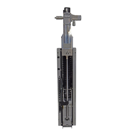
PVA PCP Series User manual

Progressive Cavity Pump
PCP Series
Operation Manual
Revision A
INNOVATION. PRECISION. EXCELLENCE.

PCP Series Manual
Revision A /September 2020
Page 2 of 46
This document is based on information available at the time of its publication. While efforts
have been made to ensure the contents of this manual are accurate, the information
contained herein does not purport to cover all specific details or variations in hardware, or
to provide for every possible contingency in connection with installation, operation, or
maintenance. Features may be described herein which are not present in all hardware and
software systems. Precision Valve and Automation, Inc. assumes no obligation of notice to
holders of this document with respect to changes subsequently made.
Precision Valve and Automation, Inc. makes no representation or warranty, expressed,
implied, or statutory with respect to, and assumes no responsibility for the accuracy,
completeness, sufficiency, or usefulness of the information contained herein. No warranties
of merchantability or fitness for purpose shall apply.
This document, including the information contained herein, is the property of
Precision Valve and Automation, Inc. and is considered confidential and proprietary
information. It is delivered on the express condition that it not be used, disclosed, or
reproduced, in whole or in part, for any reason without prior written consent of
Precision Valve and Automation, Inc.
Copyright © 2019
Precision Valve and Automation, Inc.
All Rights Reserved.

PCP Series Manual
Revision A /September 2020
Page 3 of 46
Table of Contents
Introduction .......................................................................................................................................5
PVA Contact Information ........................................................................................................5
Document History.....................................................................................................................5
Safety ..........................................................................................................................................6
System Description ................................................................................................................. 8
Theory of Operation ................................................................................................................ 8
Description of Components....................................................................................................9
Personal Protective Equipment.............................................................................................9
Waste Disposal...........................................................................................................................9
Necessary Tools ........................................................................................................................9
Setup .................................................................................................................................................10
Operation ...........................................................................................................................................11
Bleed the Pump........................................................................................................................11
Fluid Pressure..........................................................................................................................12
Material Flow Rate ..................................................................................................................12
Install the Needle ....................................................................................................................12
Snuff Back................................................................................................................................ 12
Pump Shutdown Procedure .................................................................................................13
Disassemble and Clean the Pump...............................................................................................14
Remove the Pump from the Workcell.................................................................................14
Disassemble the Pump ..........................................................................................................15
Clean All Wetted Parts ...........................................................................................................21
Assembly Instructions.................................................................................................................. 23
Assemble the Pump .............................................................................................................. 23
Install the Pump on the Workcell........................................................................................ 32
Maintenance ................................................................................................................................... 33
Replace the Dispense Needle.............................................................................................. 33
Replace the Star Shaped Coupling .................................................................................... 34
Replace the Stator................................................................................................................. 34
How to Use the PCP with Portal ................................................................................................. 35
Setup Mode ............................................................................................................................. 35

PCP Series Manual
Revision A /September 2020
Page 4 of 46
Devices............................................................................................................................. 36
Dispense ...........................................................................................................................37
Calibration ....................................................................................................................... 38
Parts Breakdown............................................................................................................................ 39
Spare Parts......................................................................................................................................40
Technical Specifications ...........................................................................................................41
Drawings...................................................................................................................................... 42
Troubleshooting......................................................................................................................... 43
Table of Figures.......................................................................................................................... 44
PVA Warranty Policy.................................................................................................................. 46

PCP Series Manual
Revision A /September 2020
Page 5 of 46
Introduction
Before you operate this valve, read the operation and setup manual. This will help you to
become familiar with the product and ensure successful operation.
If any questions or problems arise, contact PVA’s Technical Support department.
PVA Contact Information
Main Office PVA
One Mustang Drive
Cohoes, NY 12047
Tel +1-518-371-2684
Fax +1-518-371-2688
Website: http://www.pva.net
Technical Support
Tel +1-844-734-0209
Document History
Revision
Revision Date
Reason for Changes
A
August 2020
Initial Release
Note: All photographs and CAD model representations in this document are a
“general representation” of the system and its components. The actual appearance
of the system and its components can differ based upon customer specific
configuration.

PCP Series Manual
Revision A /September 2020
Page 6 of 46
Safety
Certain warning symbols are affixed to the machine and correspond to notations in this
manual. Before operating the system, identify these warning labels and read the notices
described below. Not all labels may be used on any specific system.
Always wear approved safety glasses when you operate or work near the
workcell.
Before you operate the system, read and understand the manuals provided
with the unit.
Never put hands or tools in areas with this symbol when the machine is in
operation. A dangerous condition may exist.
Read and understand the manuals provided with the unit before any repairs
or maintenance is done. Only a qualified individual should do service.
Use caution when there are pressurized vessels. Find and repair any leaks
immediately. Always wear appropriate safety equipment when you work
with pressurized vessels or vessels that contain chemicals
Shear hazard from moving parts. Avoid contact.
Do not remove protective guarding.
In situations where inattention could cause either personal injury or damage
to equipment, a warning notice is used.

PCP Series Manual
Revision A /September 2020
Page 7 of 46
Do not smoke near the machine. Always have a fire extinguisher available
for emergency use.
Before performing any repairs or maintenance to the system, turn off power
and lock out the power disconnect switch.
Warning notices are used to emphasize that hazardous voltages, current,
temperatures, or other conditions that could cause personal injury exist in
this equipment or may be associated with its use. Only qualified personnel
should enter areas designated with this symbol.
Laser light source present. Do not stare directly into the beam. Do not use in
the presence of highly reflective surfaces
Pinch hazard from moving parts. Avoid contact.
Hot surface. Avoid contact.
Warning, Ultraviolet (UV) light hazard. Do not look directly at the UV light
source.
This product meets EU standards for health, safety, and environmental
protection.
Warning, no open flames.
Electrostatic sensitive device warning. Observe precautions for handling.

PCP Series Manual
Revision A /September 2020
Page 8 of 46
System Description
This manual applies to the following Precision Valve & Automation, Inc. valves:
PCP-015
PCP015-C
PCP050
PCP050-C
PCP150
PCP150-C
PCP500
PCP500-C
PCP1000
PCP1000-C
The PCP Series of progressive cavity pumps feature a machined rotor that couples with a
rubberized seal to assure drip-free operation with a wide range of viscous chemistries.
Each servo-controlled rotor displaces a fixed volume of material per revolution. This true
positive displacement process assures consistent volume regardless of slight material
variations.
The PCP Series features five different rotor sizes allowing the end user to select their ideal
flow rate. An optional carbide rotor allows processing of filled or abrasive chemistries while
extending the life of the rotor.
Theory of Operation
The PCP Progressive Cavity Pump is a high precision, rotating, positive displacement
pump. It dispenses high precision beads or dots of almost any chemistry or viscosity.
The pump contains a stainless steel or carbide rotor and an elastomeric seal (stator). The
PCP uses the principal of the “endless piston,” and is a progressive cavity pump that
provides pulse-free, drip free dispensing. Reverse operation of the pump will cause “suck
back” or “snuff back” which gives excellent shut off.

PCP Series Manual
Revision A /September 2020
Page 9 of 46
Description of Components
Component
Description
Electric Motor
The motor turns the rotor. Motor speed can be fully adjusted to
change the flow rate.
Rotor
The rotor is a stainless-steel or carbide helical shaft. A fixed
volume of material is moved as it rotates inside the stator and
uses the principal of the “endless piston”.
Stator
The stator is an elastomeric seal with a double helix molded into it.
The stator lets material flow when the rotor turns but has a
perfect seal when the rotor is stopped.
Manifold
The manifold is fed by the rotor/stator and supplies it to the
dispense needle through the material outlet.
Personal Protective Equipment
Operators must use eye protection because material contents are under pressure. Always
wear gloves when handling materials and solvents. Refer to MSDS sheets on the material
being dispensed for other precautions.
Waste Disposal
Dispose of all used parts and materials in accordance with local laws and regulations.
Necessary Tools
PVA offers tools and cleaning accessories to maintain the PCP progressive cavity pumps.
Part Number
Description
12862
Stator Tool
02506
Hook and Pick Set
Figure 1: Necessary Tools

PCP Series Manual
Revision A /September 2020
Page 10 of 46
Setup
Before you operate the pump, know the pump components. Do the steps instructed below
for safe and correct operation.
WARNING: Never operate the pump dry. If the pump is operated dry or without pump
conditioner, severe damage will occur. Always put pump conditioner on the rotor
before the pump is assembled. Refer to Section 9 for more information on how to
order pump conditioner.
1. Use the mounting holes to install the PCP onto the workcell.
2. Attach the fluid supply line to the related fluid inlet.
Make sure the fluid fittings are tight and do not leak.
3. Attach the motor cable and make sure the routing of the cable is correct.
Make sure the motor connection on the pump is tight and that the prongs are not
bent.

PCP Series Manual
Revision A /September 2020
Page 11 of 46
Operation
WARNING: Never operate the pump dry. If the pump is operated dry or without pump
conditioner, severe damage will occur. Always apply lubricant to the rotor before the
pump is assembled.
Operation Notes:
•You must do the initial bleed for the pump to function correctly.
•Make sure the material is supplied correctly to the pump.
The sections that follow are in the recommended order to operate the pump. To operate
the pump, do every sub-section in Section 3, in the order shown.
Bleed the Pump
1. Open the bleed clip.
2. Turn the bleed clip counterclockwise to loosen. Turn one full rotation then slowly
until material appears.
3. Turn one full rotation and then slowly until the material begins to bleed.
4. Let the material flow from the material outlets until there are no breaks in the
material flow.
NOTE: Any break in the flow of the material shows there is still air in the system.
Bleed the pump until the material flows smoothly without any breaks in the flow.
NOTE: The fluid supply operating pressure must be have a flow rate equal to or more
than the maximum flow rate capacity of the pump.
5. Clean all material from the manifold and material outlets.
6. Close the bleed clip by spinning it clockwise until there is resistance.
7. Close the door of the bleed clip.

PCP Series Manual
Revision A /September 2020
Page 12 of 46
Fluid Pressure
The resistance of flow through the dispense needle have an effect on the outlet fluid
pressure. The size of the static mixer and dispense needle, the viscosities of the fluids, and
the flow rate also all have an effect on the outlet fluid pressure.
•The maximum outlet fluid pressure is 285 psi.
Material Flow Rate
Material flow rate can be adjusted in Auto Cycle or Manual mode through PVA Portal. Refer
to the Portal instructions in your workcell manual. An alternative is to adjust the path
speed in PathMaster instead of material flow rate. Refer to your PathMaster manual.
Install the Needle
After the system has been bled, you must install the needle.
1. Push the needle up and twist to attach it.
2. Use the purge function to release all air from the needle.
Snuff Back
The “snuff back” function prevents strings or drips of material at needle tip after material is
dispensed. Snuff back is the when the pump operates in the opposite direction for a short
period and causes the material to flow in the opposite direction also. Snuff back removes
the fluid pressure from the static mixer and needle to stop strings or drips at the needle tip.
WARNING: Snuff back makes the pumps operate in the opposite direction and it is
possible that mixed material from the static mixer is pulled back into the pumps. Use
the minimum snuff back or material will cure in the pump.
1. Use PVA portal to adjust the snuff back time for your application.
2. If the needle tip drips or has strings of material when the valve is closed, increase
snuff back.
3. If material cures in the pump assembly, decrease snuff back.
4. Contact PVA for additional information on snuff back adjustment.

PCP Series Manual
Revision A /September 2020
Page 13 of 46
Pump Shutdown Procedure
1. Remove the needle from the manifold.
2. Purge material through the manifold.
3. Completely clean the manifold material outlet.
4. Install a night cap on the manifold material outlet.
5. Release the fluid supply pressure. Refer to the workcell manual if necessary.

PCP Series Manual
Revision A /September 2020
Page 14 of 46
Disassemble and Clean the Pump
Remove the Pump from the Workcell
1. Remove the motor connection from the motor assembly of the pump.
2. Turn the luer lock dispense tip counterclockwise and pull to remove.
3. Discard the luer lock dispense tip.
4. Use a wrench to remove the material fitting from the fluid body.
5. Install a cap on the material fitting.
6. Use a 2.5 mm hex key to remove the bolt from the back of mount plate in the back
of the fluid body.
Figure 2: Remove Pump from Workcell
7. Remove the pump from the workcell.

PCP Series Manual
Revision A /September 2020
Page 15 of 46
Disassemble the Pump
1. Place the pump on a clean work surface.
2. Use a 2.5 mm hex key to remove the two M3 x 55 mm socket head cap screws from
the rotor assembly.
3. Separate the motor from the rotor assembly.
Figure 3: Separate Motor from Rotor Assembly
4. Remove the blue coupling from the rotor assembly.
Figure 4: Remove Coupling

PCP Series Manual
Revision A /September 2020
Page 16 of 46
5. Twist to unscrew the luer lock and remove it from the stator sleeve.
Figure 5: Remove Luer Lock
6. Twist to unscrew the union cap and remove it from the stator sleeve.
Figure 6: Remove Union Cap

PCP Series Manual
Revision A /September 2020
Page 17 of 46
7. Remove stator sleeve.
Figure 7: Remove Stator Sleeve
8. Install the stator tool onto the rotor assembly.
Figure 8: Install Stator Tool

PCP Series Manual
Revision A /September 2020
Page 18 of 46
9. Hold the stator tool to stabilize and twist counterclockwise to remove the stator.
Figure 9: Remove Stator
10. Twist to remove the bleed clip from the vent port.
Figure 10: Remove Bleed Clip

PCP Series Manual
Revision A /September 2020
Page 19 of 46
11. Remove the o-rings from the fluid block assembly.
12. Examine the o-rings for damage. Save it if it is not damaged. Replace it if it is
damaged.
Figure 11: Remove O-Ring
13. Use a 2.5 mm hex key to remove the two M3 x 35 mm socket head cap screws from
the rotor assembly.
Figure 12: Remove Screws from Rotor Assembly
14. Separate the fluid block from the seal block/rotor assembly.
Figure 13: Separate Fluid Block

PCP Series Manual
Revision A /September 2020
Page 20 of 46
15. Remove the o-ring from the fluid block.
16. Examine the o-ring for damage. Save it if it is not damaged. Replace it if it is
damaged.
Figure 14: Remove O-ring from Fluid Block
17. Remove the o-ring from the seal block.
18. Examine the o-ring for damage. Save it if it is not damaged. Replace it if it is
damaged.
Figure 15: Remove O-Ring from Seal Block
This manual suits for next models
10
Table of contents
Other PVA Water Pump manuals