Pyramid PM-8501 User manual

Studio
—=.
PRO
OWNER’S
MANUAL
MODEL
PM-850l/PM-800l/PM-750l/PM-4001
www.pyramidcaraudio.com

INTRODUCTION
Thank,
you
for
purchasing
-the
PYRAMID
Professional
DJ
Mixer
The
Mixer
has
been
designed
as
a
sophisticated
control
center,
perfect
for
mixing
sound
sources
from
multiple
playback
sources
or
from
live
performances,
it
offer
you
the
best
features
to
adjust
sound
levels,
create
the
special
sound
performance
and
tailor
the
sound
to
compensate
for
environmental
conditions
or
for
personal
preference.
FEATURES
1.
Power
on/off
3.
Dual
LED
Meter
5.
MIC
1
Talkover
7.
MIC
1
Treble
Tone
Control
9.
Dual
Railed
Removable
Crossfader
11.
Channel
Volume
Control
1$.
7-Band
Frequency
Equalizer
15.
M
ONO/STEREO
Selector
2
BNC
Lamp
Adaptor
4.
MIC
1
XLR
input
6
MIC
1
Bass
Tone
Control
8.
MIC
1
Level
Control
10.
Crossfader
Assign
Switch
12.
input
Device
Selector
14
EQ
Bypass
Switch
16.
M
aster
Level
control
17.
C
UE
Assign
Selector
18.
CUE
Level
Control
19.
Head
Phone
Jack
20.
CUE/MASTER
Fader
<PM-8001/PM-4001|
21.
ECHO
ON/OFF
Switch
(PM-8501/PM-8001)
22.
ECHO
DELAY
Control
(PM-8501/PM-8001)
25.
ECHO
REPEAT
Control
(PM-a50l/PM-fiOOl)
24.
ECHO
LEVEL
Control
(PM-85O1/PM-8O01)
25
Digital
Sound
Effect
(PM-8501/PM-7501)
26.
Sound
Effect
SPEED
Control
(PM-8501/PM-7501)
27.
Sound
Effect
VOLUME
Control
(PM-8501/PM-7501)
26
Input
Devices
MIC
2
'Hi
or
lq
impedance
CHANNEL
T
PHONO
1,
LINE
1
CHANNEL
2:
PHONO
2,
LINE
2
CHANNEL
3
LINE
3,
UNE
4
CHANNEL
4:
LINE
5.
UNE
6
2


FUNCTIONS
1
P
ower
ON/OFF
Push
in
to
turn
power
on,
push
again
to
turn
power
off.
2
BNC
LAMP
ADAPTOR
Let
you
connect
o
12W3W
max
lamp
to
light
up
the
unit
3
DUALLED
METER
Indicate
the
output
signal
level
of
the
master
channel,
4.
MIC
1
XLR
INPUT
For
connentjng
balanced
or
unbalanced,
low
impedance
XLR
type
micro*
phone.
5.
MIC
1
AUTO
TALKOVER
Allows
yOU
JO
lowers
the
sound
Of
the
input
sources
so
you
can
talk
over
them
using
the
DJ’s
microphone.
6
MIC
1
BA$$
TONE
CONTROL
Let
you
adjust
the
bass
or
the
primary
microphone
(MIC
1)
to
improve
the
DJ'S
sound.
7.
MIC
1
TREBLE
TONE
CONTROL
Let
you
adjust
the
treble
of
the
primary
microphone
(MIC
i)to
improve
the
DJ's
sound.
8.
MIC
1
LEVEL
CONTROL
Let
you
control
the
microphone's
volume
level
so
you
can
adjust
it
before
mixing
in
it
9
DUAL
RAILED
REMOVE
ABLE
CROSS
FADER
Let
you
smoothly
switch
between
two
input
sources,
10.
CROSSFADER
ASSIGN
SWITCH
Let
you
quickly
and
smoothly
switch
between
two
assigned
sources
of
each
playing
channel.
11.
CHANNEL
VOLUME
CONTROL
Slide
towards
to
increase
volume
of
the
channel,
downwards
to
decrease.
12.
INPUT
DEVICE
SELECTOR
Let
you
select
the
input
source
of
each
playing
channel
13
7-BAND
FREQUENCY
EQUALIZER
Aflows
you
to
tailor
the
sound
output
to
your
preference.
5

FUNCTIONS
14
EQ/BYPASS
SWITCH
Push
in
to
operate
equalizer
function,
push
out
to
defeat
equalizer
function
15.
MONO/STEREO
SELECTOR
Push
in
to
get
MONO
master
output,
push
out
to
gel
STEREO
master
output
16.
MASTER
LEVEL
CONTROL
Let
you
control
the
mixer's
overall
volume
level
17.
CUE
ASSIGN
SELECTOR
Let
you
select
the
channel
where
the
desired
audio
input
source
is
located
so
you
can
monitor
and
prepare
it
before
mixing
it
in
18.
CUE
LEVEL
CONTROL
Let
you
adjust
the
headphone's
volume
level.
19.
HEAD
PHONE
JACK
6.3
mm
jack
head
phone
connection.
20
CUE/MASTER
FADER
{PM-8001/PM-4C01)
Let
you
adjust
the
level
of
monitoring
signal
between
assignd
cue
and
master
output.
21
ECHO
ON/OFF
SWITCH
{PM-8501/PM-8001)
Set
the
switch
to
ON
to
activate
the
echo
mode.
22.
ECHO
DELAY
CONTROL
(PM-85Q1/PM-8CCH)
Let
you
adjust
the
delay
time
of
echo.
23.
ECHO
REPEAT
CONTROL
(PM-8501/PM-8001)
Let
you
control
the
length
of
time
a
tone
is
repeated.
24.
ECHO
LEVEL
CONTROL
(PM-850VPM-8001J
Let
you
control
the
output
level
of
the
echo
effect.
25.
DIGITAL
SOUND
EFFECTS
(PM-8501/PM-7501)
Let
you
create
the
special
sound
performance
from
the
six
pre*programed
sound
effects.
26.
SOUND
EFFECT
SPEED
CONTROL
(PM-8501/PM-75O1)
Let
you
adjust
the
pitches
of
the
sound
effects.
27.
SOUND
EFFECT
VOLUME
CONTROL.
(PM-850l/PM-760t)
Let
you
adjust
the
volume
of
the
sound
effects
6
AUDIO
CONNECTION
1.
CONNECTING
INPUT
A.MICROPHONE
INPUT
g,
MIC
1
Connect
a
balanced,
low
impedance
(60O-ohm)XLR
type
microphone
to
the
XLR
receptacles
on
the
upper
left
comer
of
the
mixer's
tront
panel.
b
MIC
2
Connect
a
high
quality,
high
impedance
(1
Ok-ohm)
or
low
impedance
(600*ohm)
microphone
with
a
1/4-inch
plug
to
1
/4-inch
jack
on
the
lower
left
corner
of
the
mixer’s
back
panel
Set
the
switch
above
the
volume
control
of
MIC
2
channel
to
select
the
input
you
want
to
activate.
Set
to
HI
when
using
a
high
impedance
micro¬
phone,
or
LO
when
using
a
low
impedance
microphone.
B.
LOW
LEVEL
AUOlO
SOURCE
INPUT
Connect
up
to
two
iow-tevel
audio
sources
(such
as
magnetic-cartridge
turntables
into
PHONO
1
and
PHONO
2
NOTE;lf
you
connect
a
turntable
with
a
magnetic
cartridge,
connect
its
ground
wire
(usually
black
or
green)
to
GND.
C.
KIGH
LEVEL
AUDIO
SOURCE
INPUT
Connect
up
to
six
high-level
audio
sources
(such
as
a
tuner,
cassette
tape
deck.
CD
player,
camcorder,
Or
VCR)
to
LINE
1.
LINE
2.
LINE
3,
LINE
4,
UNE
5,
and
LINE
6.
D
CAUTION.
Do
not
connect
an
audio
source
with
a
HGH
LEVEL
OUTPUT
into
MIC
or
PH,
An
audio
source
S
output
is
HIGH
LEVEL
if
you
can
raise
or
lower
its
volume
with
its
volume
control.
7

AUDIO
CONNECTION
2
CONNECTING
OUTPUT
A
AMP
OUTPUT
To
p8ay
the
mixer's
output
signal
through
your
speaker
system
(tor
events
such
as
parties,
dances,
conferences,
etc.
),
connect
an
audio
patch
cord
(not
supplied)
from
the
mixer’s
AMP
R
and
L
jacks
to
your
receiver/ampli-
fier's
left
and
right
inout
jacks.
B.
REC
OUTPUT
To
record
the
mixer's
output
signal,
connect
an
audio
patch
cord
(not
supplied)
from
the
mixer’s-
REC
R
and
L
jacks
to
your
tape
deck's
left
and
right
input
jacks
C.
CAUTION;
To
avoid
sudden
and
unusable
sound
outputs
from
the
audio
devices,
adjust
the
audio
devices-'
controls
to
these
settings
before
you
connect
the
mixer’s
output
jacks
to
the
audio
devices'
Input
jacks.
AUDiO
DEVICE
CONTROL
SETTING
Tape
Deck
POWER
OFF
Amplifier/Receiver
POWER
OFF
TONE
FLAT
3.C0NNECT1NQ
A
LAMP
The
mixer
is
equipped
with
a
i2v
BNC
lamp
adaptor
for
connecting
a
12V/3W
max
lamp
so
you
can
see
the
control
panel
in
a
dark
place
NOTE.
Use
only
a
lamp
with
exact
same
specification
as
above.
&
&
s
8
OPERATION
1
HEAD
PHONES
To
listen
In
privacy
or
monitor
the
audio
source
inputs
so
you
can
locate
on
exact
passage
or
section
before
mixing
it.
plug
a
pair
of
stereo
headphones
with
a
1/4
inch
plug
into
the
PHONES
jack
on
the
lower
right
front
corner
of
the
mixer
2.MONITORING
THE
INPUTS
A
Sef
POWER
ON/OFF
to
ON
10
turn
on
the
mixer's
power
ThePOWERLED
Indicator
lights.
B.
Turn
on
the
audio
input
source
you
want
to
mix,
and
sel
it
to
play
(or
contin¬
uously
talk
into
microphone)
C.
Set
the
CUE
ASSIGN
to
the
audio
input
souracs
(MIC,
CH
1,
CH
2,
CH
3,
or
CH
4)
you
want
to
monitor,
so
you
can
decide
when
to
mix
in
each
input
and
play
them
through
your
amplifier
system
or
record
them
on
your
tape
deck
D.
Turn
the
CUE
LEVEL
control
to
adjust
the
heaefchon©
volume
without
effect*
ing
the
overall
mix.
ETurn
the
CUE/MASTER
FADER
control
to
-adjust
the
monitoring
signal
level
between
the
assigned
cue
source
and
the
master
output
(PM-8001/PM-
4001).
3
MIXING
THE
INPUTS
A.
The
maximum
available
audio
input
sources
you
can
mixing
are:
MIC
2.
HI
or
LO
Impedance
microphone.
PHONO
PHONO
1
and
PHONO
2.
To
mix
the
turntable
connected
to
the
PHONO
jacks.
LINE'
LINE
1,
LINE
2,
LINE
3,
LINE
4,
LINE
5,
and
LINE
6
To
mix
any
high-
level
output
audio
sources
connected
to
the
LINE
jacks
B.
Set
the
selected
audio
ir^ut
sources
to
play
C
Set
the
corresponding
MIC.
PHONO,
and
LINE
volume
oomrols
to
approxi¬
mately
8-10.
D.Set
the
INPUT
DEVICE
selector
as
desired
MIC
2:
HI
or
LO
impedance
microphone
CH
1:
PHONO
1
or
LINE
1.
CH
2:
PHONO
2
or
LINE
2
CH
3
LINE
3
or
LINE
4.
CH
4.
LINE
5
or
LINE
6.
9
OPERATION
E.
Rotate
the
MASTER
volume
control
toward
10
until
you
get
an
average
read*
ing
of
0
on
both
output
level
LED
meters
NOTE.Once
you
set
the
MASTER
volume
control
do
not
move
it
away
from
its
initial
setting
The
output
level
of
LED
meter
indicate
the
total
output
signal
levels
(both
the
left
and
right
channels)
of
all
the
input
sources
being
mixed
F.
Set
EQUALIZER
ON/BYPASS
as
desired
You
can
tailor
the
sound
processed
through
the
mixer
lo
match
your
a
acoustic
surrounding
and
swt
your
personal
preference
with
the
seven
slid¬
ing
frequency
controls.
G.
When
adding
an
audio
input
source,
adjust
the
corresponding
MIC,
PHONO,
and
LINE,
volume
controls
so
you
can
get
an
average
reading
of
0
or
both
output
level
LED
meters
H.
Adjust
the
receiver
amplifier's
(not
the
mixer’s)
volume
control
to
the
desred
volume.
I
To
turn
off
the
mixer,
set
POWER
ON/OFF
to
OFF.
The
POWER
LED
light
turn
off.
4.
USING
THE
7-BAND
FREQUENCY
EQUALIZER
With
the
seven
sliding
frequency
controls,
you
can
tailor
the
sound
processed
through
the
miser
to
compensate
for
the
acoustic
surroundings
and
to
suit
your
personal
preference
Set
the
EQ
switch
to
ON
to
turn
on
the
frequency
equalizer
Then
slide
the
control
up
to
boost
the
indicated
frequency
range,
or
down
to
reduce
it.
Each
control
varies
by
+/*
l2dB
the
level
of
a
narrow
band
of
frequencies
centered
around
the
frequency
noted
between
the
controls
(60,
150,
400.
Ik.
2.4k,
6k
and
15k
Hz).
NOTE.
If
you
set
the
control
to
the
center
position,
the
frequency
range
is
unaltered.
10

OPERATION
In
order
to
provide
smooth
frequency
control
the
effect
of
these
controls
must
overlap
slightly
Thus,
the
Ik
Hz
control
has
a
slight
effect
on
the
range
of
frequencies
covered
by
the
400
Hz
and
the
2.4k
Hz
controls
SO
Hz:
Adjust
the
frequency
in
the
low
bass
range
(fow
organ
notes
and
bass
drums).
Reduce
rumbles
or
other
low-frequency
noise.
You
can
also
use
this
control
to
compensate
for
poor
bass
response
in
a
recording
or
to
reduce
rumbler
or
other
low
frequency
deficiencies.
150
Hz,
Adjust
the
frequencies
in
the
low
to
middle-bass
range
(tuned
drums,
timpani
and
seme
low-bass
instruments
400
Hz.
Adjust
frequencies
in
the
upper*bass
range
An
over
accentuated
upper
bass
yields
a
muddy,
boomey
sound.
Too
little
upper
bass
makes
the
music
sound
hollow
and
thin.
IK
Hz
Adjust
the
range
of
frequencies
in
the
middle
frequency
range
where
the
ear
is
most
sensitive
(vocals).
Boosting
this
range
enhances
the
vocals,
cutting
it
makes
the
vocals
blend
back
into
the
ensemble
This
effent
is
often
called
'presence'.
2.4K
Hz
Adjusts
the
range
of
frequencies
in
the
upper*middle
frequency
range
that
include
vocals
and
some
upper-midrange
mstruments(such
as
clar¬
inet
and
saxophone).
Boostng
this
range
presence
makes
the
program
sound
'brighter
1
6K
Hz:
Adjust
the
range
of
frequencies
in
the
louver
high
frequency
range
that
includes
flutes,
oboes,
viohne,
piccfois
and
other
treble
instruments.
Boosting
this
range
adds
vibrancy
to
the
upper
voices,
Too
much
boost
can
make
the
music
sound
harsh
15K
Hz'
Adjust
the
high-frequency
sounds
(such
as
cymbals
and
other
high-
frerquency
sounds).
Boosting
this
range
adds
brilliance
to
the
music.
Boosting
high-frequency
too
much
makes
the
music
piercing
and
unpleasant
Boosting
too
little
causes
the
program
to
loss
its
brllicmco
and
dimensionality
11
OPERATION
5.USING
THE
DJ'S
MICROPHONE,
MIC
1
A
TALKOVER
switch
a
TALK'
Set
this
switch
to
TALK,
all
outputs
except
MIC
1
and
MIC
2
are
attenuated.
Only
your
voice
can
be
heard
dearly
through
MIC
1
bAUTO'
Set
this
switch
to
AUTO
MUTE,
it
is
a
function
of
AUTO
TALKOVER
all
outputs
are
automatically
attenuated
as
long
as
you
are
speaking
c.QFF.
When
not
using
MIC
1,
set
this
switch
to
OFF,
all
Outputs
return
to
same
level.
This
method
is
useful
when
paging
B
BASS
and
TREBLE
Tone
controls
you
can
tailor
the
high
and
low
frequency
sounds
of
MIC
1
processed
through
the
mix
to
fit
the
acoustic
surroundings
and
your
personal
taste
using
the
BASS
or
TREBLE
tone
controls
To
enhance
the
sounds,
rotate
BASS
or
TREBLE
towards
+10.
To
reduce
them,
rotate
BASS
or
TREBLE
towards
*10
To
resume
normal
sound,
set
them
to
the
middle
position
C.
LEVEL
control
For
a
binding
of
voice
and
music,
adjust
the
miC
i
LEVEL
to
increase
or
decrease
the
microohone
level
without
affecting
the
main
volume
incuts
Set
MIC
1
LEVEL
to
0
when
not
using
the
DJ'S
microphone.
6
USING
MONO/
STEREO
When
you
set
MONO/STEREO
to
MONO,
the
mixer
combines
the
left
and
right
channels
then
sends
the
signals
to
OUTPUT
R
and
L
jacks.
The
combined
output
signals
can
be
used
by
a
monaural
amplifier,
such
os
a
PA
amplifier.
When
you
set
MONO/STfcREO
to
STEREO,
the
mixer
keeps
tho
left
and
right
stereo
channels
separated,
then
sends
the
signals
to
the
OUIPUT
R
and
L
jacks.
The
stereo
Output
signals
can
be
used
by
a
stereo
amplifier
or
tape
deck.
7.USING
THE
CROSSI-ADER
When
two
channels
ore
playing
at
the
same
time,
slide
CROSSFADER
to.
A
<A'
To
fade
in
the
input
source
selected
by
ASSIGN
A
and
fade
out
the
input
source
selected
by
ASSIGN
fi
12
OPERATION
B
B>
To
fade
in
-the
irput
source
selected
by
ASSIGN
B
and
fade
out
the
input
source
selected
by
ASSIGN
A.
C.
Ttie
center:
To
mix
the
input
source
selected
by
ASSIGN
A
and
ASSIGN
B
earually
8.USING
THE
ECHO
(PM-8501/PM-8QC1)
A
The
echo
mode
is
applied
to
the
sound
after
all
the
inputs
are
mixed
B.
Set
the
ECHO
ON/OFF
to
ON
to
turn
on
the
echo
mode
and
activate
the
DELAY
and
REPEAT
functions.
C.
The
DELAY
control
lets
you
include
a
measured
time
delay
to
simulate
on
echo
Set
DELAY
towards
lO
for
a
maximum
time
delay
and
towards
0
for
a
minimum
time
delay.
D
The
REPEAT
control
lets
you
control
the
length
of
lime
a
tone
is
repeated
(reverberation).
Set
REPEAT
towards
10
for
the
longest
time
and
towards
0
for
the
shortest
time.
E.The
LEVEL
control
lets
you
control
the
output
level
of
the
echo
effect
Set
LEVEL
towards
10
for
raising
the
level
and
towards
0
for
lowering
the
level
9.USING
THE
SOUND
EFFECT
<PM-850l/PM-750l>
A.There
are
six
pre-program
ed
sound
effects
for
your
selection,
LASER,
MACHINE
GUN,
TRON
BLAST.
SIREN.
EMERGENCY,
and
UFO.
Press
any
button
of
sound
effects
to
generate*
the
sound
you
wish
to
mix.
it
will
play
continously
until
you
release
the
button
to
stop
B
The
SPEED
Control.
Lets
you
adjust
the
pitches
of
the
effects.
C.The
VOLUME
Control'
Lets
you
adjust
the
volume
of
the
effects
13
TROUBLESHOOTING
Your
mixer
should
require
very
little
maintenance
If
you
have
problems,
refer
to
this
chart
for
possible
solutions
NOTHING
WORKS
Check
the
AC
power
connection
Make
sure
the
AC
outlet
is
"live".
Check
the
power
connection
to
the
rest
of
the
system
(amplifier/receiver
etc.)
NO
SIGNAL
FROM
AN
Check
the
control
setting
AUDIO
INPUT
SOURCE
Check
the
connection
between
the
mixer
and
the
input
source
HUM
FROM
PHONO
Check
the
turntable’s
ground
wire
(usually
black
or
green)
to
the
mixer.
HUM
FROM
OTHER
Make
sure
there
are
no
low
level
inputs
connects
to
LINE
input
jacks.
FEEDBACK
Move
the
microphone
further
away
trom
the
output
"SEQUELS"
speakers
or
use
a
directonal
microphone
14
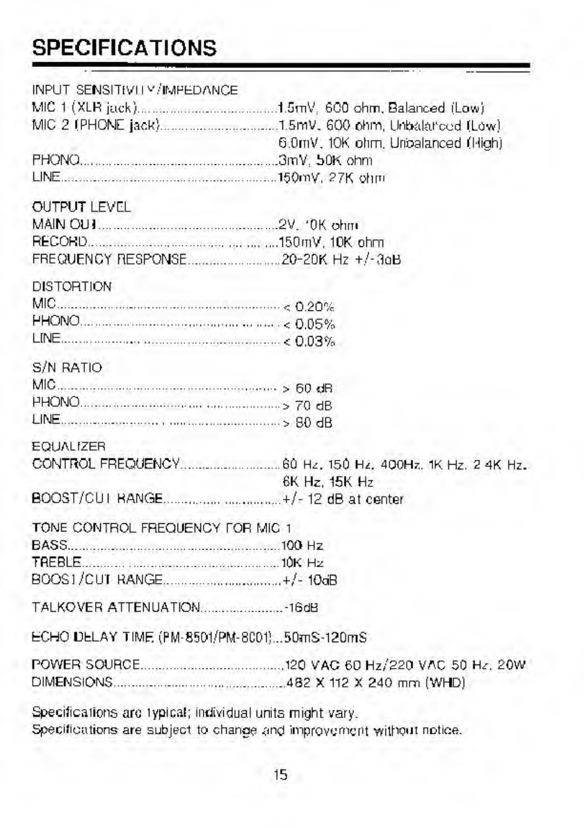
SPECIFICATIONS
INPUT
SEMSITIVII
v/IMPfcDANCE
MIC
1
(XLR
juck)
.
1
SCO
ohm.
Balanced
(Low)
MIC
2
IPHONl
jack'
.1
5mv.
600
ohm,
LlnbakU'ccd
ILow)
GOrnV.
10K
ohm.
Urioalanced
IMiahj
PHONO.3mV
bOK
ohm
LINE.150mV.
?7K
ohm
OUTPUT
LEVEL
MAIN
Oil
]
.
2V.
'OK
ohm
RECORD.150mV.
10K
ohm
FREQUENCY
RESPONSE
....
20-20K
Hz
+
/-3aB
DISTORTION
MIC.
<
o
20%
RHONO.
<
0.05%
LINE.
.<
0.03%
S/N
RATIO
MIC.>
60
dR
PHONO
.
>
70
dB
LINE.
>
80
dB
EQUAL
fZER
CONTROL
FREQUENCY.60
I-U.
150
H
i.
dQOHz.
IK
Hz.
2
4K
Hz.
6K
Hz,
15K
Hz
BOOST/CU
I
RANGE
.
+/-
12
dB
al
center
TONE
CONTROL
FREQUENCY
TOR
MIC
1
BASS.
.100
Hz
TREBLE.lOK
Hz
BOOSl/CUI
RANGE.+/-10dB
TALKOVER
ATTENUATION
.-l6dB
ECHO
DELAY
TIME
(PM-8501/PM-8C01!
..50mS-l20mS
POWER
SOURCE.
.
.120
VAC
60
Hz/220
VAC
50
Hz.
20W
DIMENSIONS.482
X
112
X
240
mm
(WHD)
Specifications
arc
lypical;
individual
units
might
vary.
Spec
ill
cations
are
subject
to
chanoe
and
improvement
without
notice.
15

This manual suits for next models
3
Table of contents


