Pyro-Chem FM-200 User manual

®
MANUAL NO. 570000-02
NOVEMBER 1, 2001
FFMM--220000®
'TOTAL FLOODING'
FIRE SUPPRESSION SYSTEM
ENGINEERED SYSTEM
INSTALLATION MANUAL
(UL VERSION)
FIRE PROTECTION WORLDWIDE
FM-200 is a registered trademark.

INSTALLATIONGUIDE
(ENGINEERED SYSTEMS)
FM-200®'TOTAL FLOODING'
FIRE SUPPRESSION SYSTEM
PYRO-CHEM
ONE STANTONSTREET
MARINETTE, WISCONSIN 54143-2542
U.S.A.
TELEPHONE: 800 526-1079........FAX: 877 329-7976
www.pyrochem.com
WARNING: THE DISCHARGE OF CLEAN AGENT SYSTEMS TO EXTINGUISH A FIRE CAN
RESULT IN A POTENTIAL HAZARDTO PERSONNEL FROM THE NATURAL FORM OF THE
CLEANAGENTORFROMTHEPRODUCTS OFCOMBUSTIONTHAT RESULTFROMEXPO-
SURE OF THE AGENTTOTHE FIRE OR HOT SURFACES.UNNECESSARY EXPOSURE OF
PERSONNEL EITHER TO THE NATURAL AGENT OR TO THE PRODUCTS OF DECOMPO-
SITION SHALL BE AVOIDED.
Rev. 2UL EX 4986 November 1, 2001

SECTION 1 - INTRODUCTION Page Rev. Date
About this Manual. . . . . . . . . . . . . 41 4-2-01
Definitions. . . . . . . . . . . . . . . . . 4
Contacts . . . . . . . . . . . . . . . . . . 4
Introduction . . . . . . . . . . . . . . . . 4
Approvals and Standards . . . . . . . . . 51 4-2-01
Health and Safety . . . . . . . . . . . . . 5
FirstAid . . . . . . . . . . . . . . . . . . 5
FM-200® Agent Characteristics . . . . . 61 4-2-01
Agent Physical Properties . . . . . . . 6
Table 1: Toxicology/Environmental . . 6
SECTION 2 - SYSTEM COMPONENTS
System Components. . . . . . . . . . . . 7 2 11-1-01
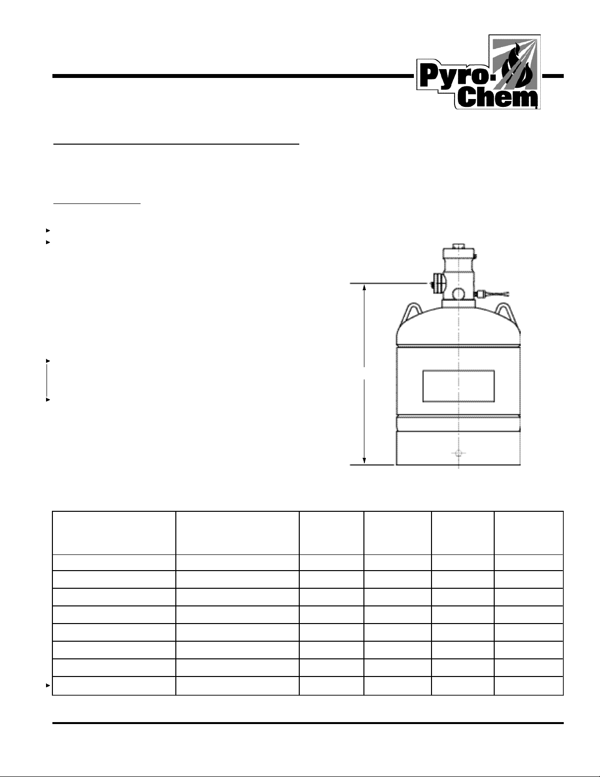
FM-200® Tank . . . . . . . . . . . . . 7
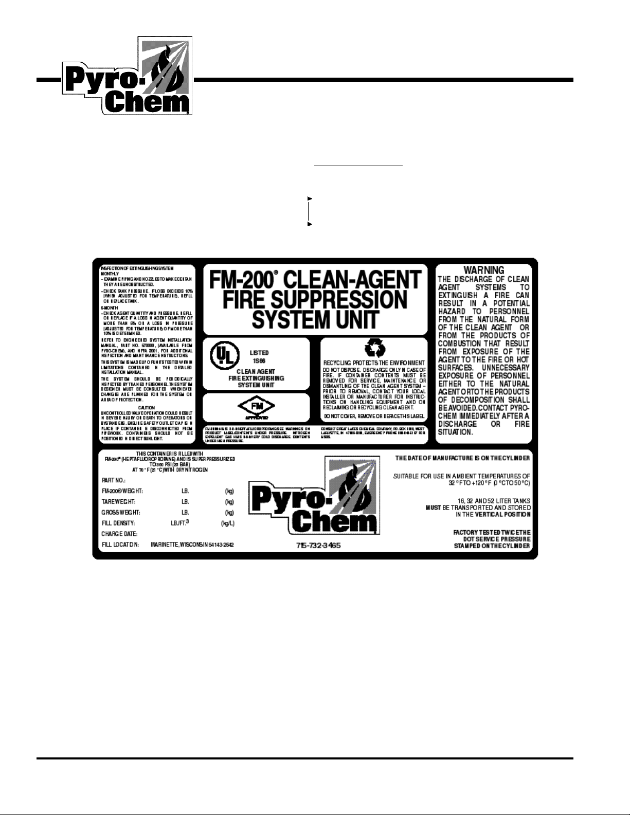
Tank Label . . . . . . . . . . . . . . . 8 2 11-1-01
Mounting Bracket. . . . . . . . . . . . 9 2 11-1-01
ValveAssembly. . . . . . . . . . . . . 9
Principle of Operation . . . . . . . . . 9
Burst Disc . . . . . . . . . . . . . . . 10 2 11-1-01
Low Pressure Switch . . . . . . . . . 10
ManualActuator. . . . . . . . . . . . 11 1 4-2-01
PneumaticActuator . . . . . . . . . . 11
Removable Electrical Actuator . . . . 11
Side Mounted Electrical Actuator. . . 12 2 11-1-01
Flexible Discharge Hose . . . . . . . 12
3 in. Discharge Hose/
Check ValveAssembly . . . . . . 12.1 New 11-1-01
3 in. Single Tank Adaptors . . . . . 12.1
3 in. Single Tank
Discharge Hose . . . . . . . . . . 12.1
SolenoidAdaptor . . . . . . . . . . . 13.......1......4-2-01
Manifold Check Valve. . . . . . . . . 13
Manifold Inlets . . . . . . . . . . . . 14 1 11-1-01
Manifold Construction . . . . . . . . 15 1 11-1-01
Manifold Construction . . . . . . . 15.1 New 11-1-01
Flexible Pilot Hose . . . . . . . . . . 16 2 11-1-01
Male Pilot Hose Connector . . . . . . 16
MaleAdaptor . . . . . . . . . . . . . 16
Male Tee. . . . . . . . . . . . . . . . 17 2 11-1-01
Male Elbow . . . . . . . . . . . . . . 17
Street Elbow. . . . . . . . . . . . . . 17
Pressure Switch . . . . . . . . . . . . 17
Discharge Nozzle . . . . . . . . . . . 18 1 11-1-01
Door Sign . . . . . . . . . . . . . . . 18
Manual Release Sign . . . . . . . . . 19 2 11-1-01
Liquid Level Measuring Device. . . . 19
Typical Manifold System . . . . . . . 20
SECTION 3 - SYSTEM DESIGN Page Rev. Date
System Design . . . . . . . . . . . . . . 21......1......4-2-01
HazardAnalysis . . . . . . . . . . . . 21
Hazard Structure. . . . . . . . . . . . 21
Hazard Volume . . . . . . . . . . . . 22......1......4-2-01
Ventilation . . . . . . . . . . . . . . . 22
Temperature . . . . . . . . . . . . . . 22
Hazard Fuels. . . . . . . . . . . . . . 22
Personnel Safety. . . . . . . . . . . . 22
Agent Quantities. . . . . . . . . . . . 22
Agent Storage . . . . . . . . . . . . . 23......1......4-2-01
Manifolds . . . . . . . . . . . . . . . 23
Agent Distribution. . . . . . . . . . . 23
Agent Flow Characteristics . . . . . . . 23
Nitrogen Superpressurization . . . . . 23
Flow in Pipe . . . . . . . . . . . . . . 23
Initial Vapor Discharge . . . . . . . . 23
Trailing Vapor Pressure . . . . . . . . 23
Nozzle Selection and Location . . . . . 24......1......4-2-01
Example: Nozzle Selection . . . . . . 24
System Design Procedure . . . . . . . . 24
Design Example - Calculations . . . . . 25......1......4-2-01
Example . . . . . . . . . . . . . . . . 25
Piping Practices . . . . . . . . . . . . . 26......1......4-2-01
SECTION 4 - FLOWCALCULATIONS
Introduction . . . . . . . . . . . . . . . 27......1......4-2-01
Table 2: Weight Calculations . . . . . 27
Table 3: Altitude Correction. . . . . . 28......1......4-2-01
FM-200®Equation Calculations. . . . . 28
Engineered Systems . . . . . . . . . . . 28
Program Parameters . . . . . . . . . . 28
Program Parameters . . . . . . . . . . 29.......1......4-2-01
Program Parameters . . . . . . . . . . 30 2 11-1-01
SECTION 5 - INSTALLATION
General Information . . . . . . . . . . . 31 2 11-1-01
Tank Installation . . . . . . . . . . . . . 31
Single Tank Installation . . . . . . . . . 32 2 11-1-01
Table 7: Bracket Mounting Heights. . 32
Multiple Tank Installation . . . . . . . . 33 2 11-1-01
Manifold Installation . . . . . . . . . 33
Table 8: Manifold Bracket
Mounting Height. . . . . . . . . . . 33
Pipe Installation . . . . . . . . . . . . . 34 2 11-1-01
Table 9: US Steel Pipe Requirements. 34
Table 10: US Fittings . . . . . . . . . 34
CONTENTS
Rev. 2 UL EX 4986 November 1, 2001
Indicates Revision

SECTION 5 - INSTALLATION (Continued)
Page Rev. Date
Pipe Hangers. . . . . . . . . . . . . . 34
Table 11: Hanger Spacing. . . . . . . 34
Grounding & Electrical Clearance . . 35
Table 12: Safety Clearances. . . . . . 35
Nozzles. . . . . . . . . . . . . . . . . . 35......1.......4-2-01
Actuation Installation . . . . . . . . . . 36 2 11-1-01
Single Tank Actuation. . . . . . . . . 36
Removable Solenoid Actuator. . . . . 37......1.......4-2-01
Multiple Tank Actuation. . . . . . . . 38......1.......4-2-01
Slave Actuation Pilot Line. . . . . . . 39 2 11-1-01
Ancillary Equipment. . . . . . . . . . . 40......1.......4-2-01
Discharge Pressure Switch . . . . . . 40
Low Pressure Switch . . . . . . . . . 41......1.......4-2-01
Accessories. . . . . . . . . . . . . . . . 41
Door Signs. . . . . . . . . . . . . . . 41
Manual Release Signs. . . . . . . . . 41
Completion Procedures . . . . . . . . . 41
Pre-checks and Visual Inspections . . 41
Final Connections . . . . . . . . . . . 42......1.......4-2-01
Handover Procedures . . . . . . . . . . 42
SECTION 6 - INTEGRITY TESTING
Introduction . . . . . . . . . . . . . . . 43......1.......4-2-01
Principle . . . . . . . . . . . . . . . . . 43
Equivalent Leakage Area (ELA). . . . . 43
Below Ceiling Leakage Area (BCLA). . 43
Predicting Retention Time . . . . . . . . 43
Slab to Slab Walls . . . . . . . . . . . 43
Coordination and Planning . . . . . . . 43
Integrity Test Procedure . . . . . . . . 44......1.......4-2-01
Enclosure Evaluation . . . . . . . . . 44
Calculation . . . . . . . . . . . . . . . . 45 1 11-1-01
Leakage Location . . . . . . . . . . . . 45
SECTION 7 - SYSTEM OPERATION
General Comments. . . . . . . . . . . . 46
System Detection & Actuation . . . . . 46
General. . . . . . . . . . . . . . . . . 46
Manual System . . . . . . . . . . . . 46
Fully Automatic System. . . . . . . . 46
Fully Automatic System with
Manual Intervention . . . . . . . . . 46
Conditions During a Fire . . . . . . . . 47......1.......4-2-01
FM-200®Concentration . . . . . . . . 47
FM-200®Decomposition . . . . . . . 47
FM-200®Discharge Conditions. . . . 47
SECTION 7 - SYSTEM OPERATION (Continued)
Page Rev. Date
Actions Following a Fire . . . . . . . . 47
General. . . . . . . . . . . . . . . . . 47
Actions Immediately Following a Fire 47
SECTION 8 - MAINTENANCE
Introduction . . . . . . . . . . . . . . . 48......1.......4-2-01
User's Program of Inspection . . . . . . 48
Contract Service & Maintenance . . . . 48
Using Liquid Level Measuring Device . 49 2 11-1-01
Using Liquid Level Measuring
Device (Continued) . . . . . . . . . 49.1 New 11-1-01
6 Month/12 Month Check . . . . . . . 49.2 New 11-1-01
Mechanical Service Procedure. . . . . . 50......1.......4-2-01
Specialized Maintenance Duties. . . . . 50
Finally . . . . . . . . . . . . . . . . . 50
SECTION 9 - RECHARGE PROCEDURE
Recharging . . . . . . . . . . . . . . . . 51 2 11-1-01
Valve Teardown . . . . . . . . . . . . . 51
Valve Teardown (Continued) . . . . 51.1 New 11-1-01
Testing . . . . . . . . . . . . . . . . . 51.2 New 11-1-01
Testing . . . . . . . . . . . . . . . . . . 52 2 11-1-01
Replacing Valve Assembly to Tank . . . 52
Field Installing Liquid Level
Measuring Device. . . . . . . . . . . 52
Filling . . . . . . . . . . . . . . . . . . 53......2.....11-1-01
Tank/Valve Assembly Leakage Test . . . 54
Emptying a Charged Tank
Through the Fill Station. . . . . . . . 54......1.......4-2-01
Calibration Repeatability Test . . . . . . 54
Tank Leak Test. . . . . . . . . . . . . . 54
Tables. . . . . . . . . . . . . . . . . . . 55 2 11-1-01
SECTION 10 -APPENDIX
Warranty . . . . . . . . . . . . . . . . . 56
Disclaimers and Limitations. . . . . . . 56
Appendix A- Site Survey/
Request Form . . . . . . . . . . . 57-58......1.......4-2-01
Appendix B - Temperature Correction
Chart. . . . . . . . . . . . . . . . . . 59
Appendix C - Hughes Program
Printout. . . . . . . . . . . . . . . 61-70......1.......4-2-01
Appendix D - FM-200®Material . . 71-79
Safety Data Sheets (MSDS)
Appendix E - Weight Conversion
Tables. . . . . . . . . . . . . . . 81-100 New 11-1-01
UL EX 4986 November 1, 2001 Rev. 2
CONTENTS
Indicates Revision

About this Manual
This manual is a comprehensive guide that contains all the
information necessary to design, install and maintain the
FM-200®Engineered Suppression system supplied by
Pyro-Chem. However the manual does not address information
relating to fire detection. Refer to NFPA 2001, “Standard For
Clean Agent Fire Extinguishing Systems,” NFPA72, “National
Fire Code,” NFPA 70, “National Electrical Code,” and other
applicable standards. Also, refer to the appropriate Pyro-Chem
technical manual for detailed panel and design information.
Users of this manual are assumed to be competent fire engi-
neers with a basic knowledge of such systems. The contents are
arranged in a logical order describing the various procedures in
turn, alternatively specific sections can be referred to as
required. Users who are not familiar with the equipment should
first read the complete manual.
Definitions
FM-200®FM-200®is a registered trade mark of the Great
Lakes Chemical Corporation.
System In this manual ‘system’refers to the suppression
equipment and does not include any electrical
system which may initiate an agent release.
Engineered Hydraulic flow program used to predict the two
phase flow of FM-200®through a pipe network.
Contacts
Should any part of this manual not be understood, or there are
any queries concerning a system, please contact:
Pyro-Chem
One Stanton Street
Marinette, Wisconsin 54143-2542
Tel. 800 526-1079
Fax. 877 329-7976
Introduction
FM-200®is a clean, safe fire fighting agent for use in total
flooding automatic suppression systems. It is intended as a
long term replacement for Halon 1301 and, while maintaining
the excellent fire suppression properties of Halon, has none of
the environmental problems. Storage and distribution require-
ments are similar to Halon and the majority of system compo-
nents are identical. However, FM-200®is not a direct replace-
ment for existing Halon 1301 installations due to the difference
in agent quantity and discharge characteristics. The FM-200®
design concentration for Class A hazards is 7.17% and for
Class B hazards is at least 9.0%, therefore requiring approxi-
mately 45% additional storage capacity over that required for
Halon in the same area.
The manufacturers claim that FM-200®is safer than Halon
1301 for use in total flooding applications and the U.S.
Environmental Protection Agency (EPA) accepts extended use
exposures of up to 9%. This has been further confirmed by a
recently published HAG report. FM-200®is rated as Zero
Ozone Depletion (ODP), is electrically non-conductive, clean,
and leaves no residue. Refer to NFPA2001, “Clean Agent Fire
Extinguishing Systems,” Section 1-6 “Safety,” for additional
exposure requirements.
The systems described in this manual are 'engineered.’
Engineered systems for example can consist of several FM-
200®tanks, manifolded together and connected via a pipe net-
work to a number of discharge nozzles.
Systems may be activated mechanically or electrically.
Mechanical manual actuation is via a strike knob attached to
the tank valve. Electrical actuation is via a removable side
mounted solenoid. The solenoid can be energized automatical-
ly by a signal from a detection and alarm control panel.
Users of this manual should find that sufficient information
is provided to plan, design, purchase components, install, oper-
ate and maintain the system. However, in the event that part of
the document is not understood, or if there is any concern as to
the suitability of the protection, do not hesitate to contact one
of our application engineers for the matter to be quickly
resolved.
SECTION 1 – INTRODUCTION
4 Rev. 1 UL EX 4986 April 2, 2001

Approvals and Standards
Pyro-Chem’s manufactured equipment and the FM-200®
agent, manufactured by Great Lakes Chemical Corporation,
have acquired comprehensive approvals and listings providing
further support to the overall product.
FM-200®Agent
◆Factory Mutual (Approved)
◆Underwriters Laboratories Inc. (UL) Recognized
Component
◆NFPA 2001 Clean Agent Fire Extinguishing Systems
(Listed Alternative)
◆EPA SNAP Rpt. (Unrestricted Listed Alternative)
◆Australian Industrial Chemicals Notification (Approved)
◆German Institute for Environmental Hygiene and Medicine
(Approved)
Pyro-Chem Manufactured Systems
◆Underwriters Laboratories Inc. (UL) Listed
Pyro-Chem FM-200®Suppression System Units are to be
designed, installed, inspected, maintained, tested and
recharged by qualified, trained personnel in accordance with
The Standard on Clean Agent Fire Extinguishing Systems,
NFPA2001. To be used in accordance with Environmental
Protection Agency (EPA) Significant New Alternatives
Program (SNAP). Where determined to be appropriate by the
authority having jurisdiction, applicable NFPA Standards may
additionally be utilized to specific system requirements for
these purposes.
Health and Safety
A properly designed and installed suppression system
should not present any significant health or safety problems;
however, there are basic precautions to be taken to avoid acci-
dents, and aspects of the system operation that should be
understood. End-users often require reassurance regarding the
safety of personnel, and this can only be given if a thorough
understanding of the properties of the agent and its effects in
different situations are known.
Reference should be made to NFPA2001 for the toxic and as-
phyxiating hazards of clean agents replacements for Halon 1301.
FM-200®, like halon, extinguishes by causing a chemical
reaction with the combustion products, and does not remove
oxygen like CO2and other inert agents.
Therefore, exposure to FM-200®at the design concentration
of 7.17%, and up to 9.0%, is not hazardous to health. Exposure
to higher concentrations is permissible for limited periods.
Refer to NFPA 2001, Section 1-6 “Safety,” for exposure
requirements. As with halons, the EPA and the National Fire
Protection Association (NFPA) recommend that unnecessary
exposure to any agent be avoided and that personnel evacuate
protected areas as quickly as possible to avoid the decomposi-
tion products of the fire.
FM-200®can decompose at high temperatures to form
halogen acids. If so, their presence is readily detected as a
sharp, pungent odor long before hazardous maximum exposure
levels are reached.
The noise created by the FM-200®agent discharging can be
loud enough to startle people in the vicinity, but is unlikely to
cause any permanent injury. Turbulence caused by the high
velocity discharge can dislodge substantial objects directly in
its path, and cause enough general turbulence within the pro-
tected area to move paper and light objects.
Direct contact with the vaporizing liquid discharged from an
FM-200®nozzle has a chilling effect on objects and in extreme
cases can cause frostbite to the skin. The liquid phase vaporizes
rapidly when mixed with air and therefore limits the risk to the
immediate vicinity of the nozzle. Reduction in visibility will
occur due to the condensation of water vapor.
HMIS: 2-0-0/heptafluoropropane/contents under pressure.
0-0-0/nitrogen expellant gas/very cold, contents under pres-
sure. Consult Great Lakes Chemical Co., P.O. Box 2200, West
LaFayette, IN 47996-2200. Emergency phone 800-949-5167.
First Aid
Skin Maintain at body temperature, thaw affected area with
gentle heat. If frostbite occurs, seek medical attention.
Do not rub affected area.
Eyes Apply gentle heat. Do not allow patient to touch affect-
ed area.
WARNING
The discharge of clean agent systems to extinguish a
fire can result in a potential hazard to personnel from
the natural form of the clean agent or from the products
of combustion that result from exposure of the agent to
the fire or hot surfaces. Unnecessary exposure of per-
sonnel either to the natural agent or to the products of
decomposition shall be avoided.
UL EX 4986 April 2, 2001 Rev. 1 5
SECTION 1 – INTRODUCTION

FM-200®Agent Characteristics
FM-200®(HFC-227ea) is a clean, gaseous agent containing no
particles or oily residues. It is produced under ISO 9002 guide-
lines to strict manufacturing specifications ensuring product
purity. FM-200®leaves no residue or oily deposits on delicate
electronic equipment, and can be removed from the protected
space by ventilation.
FM-200®is thermally and chemically stable, but without
the extremely long atmospheric lifetimes associated with other
proposed halon replacements. The atmospheric lifetime of
FM-200®has been determined to be 36.5 years. The EPA does
not consider FM-200®to be a long lived substance when dis-
charged, and as such has placed no restrictions on its use.
Typical areas that can be protected by an FM-200®system
are detailed below; the list is by no means complete:
Bank Vaults
Libraries
Rare Book Stores
Electronic Data Processing
Telephone Exchanges
Studios
Communication Centers
Transformer and Switchrooms
Control Rooms
Test Laboratories
Flammable Liquid Stores
The present understanding of the functioning of FM-200®is
that 80% of its fire fighting effectiveness is achieved through
heat absorption and 20% through direct chemical means
(action of the fluorine radical on the chain reaction of a flame).
Complete suppression using FM-200®has the following
advantages:
•The low concentration of FM-200®required means less
visual obscurity and minimal risk to personnel.
•The small quantity of agent discharged minimizes over-
pressurization of the protected area.
• Maximum safety for personnel due to low toxicity.
•Most effective when used with automatic detection to intro-
duce FM-200®rapidly.
•The ability to prevent re-ignition as long as concentration
levels are maintained.
FM-200®is stored as a liquified compressed gas and is dis-
charged into the protected area as a vapor. It is stored in
approved DOT4BW450 or DOT4BW500 tanks and is super-
pressurized with dry nitrogen to 360 psi (25 Bar) at 70 °F
(21 °C).
Agent Physical Properties
Chemical Structure CF3CHFCF3
Chemical Name Heptafluoropropane
Molecular Weight 170.03
Boiling Point 1.9 °F (–16.36 °C)
Freezing Point –204 °F (–131.1 °C)
Critical Temperature 214 °F (101.7 °C)
Critical Pressure 422 psi (29.1 Bar)
Critical Volume .0258 cu. ft./lb. (274 cc/mole)
Critical Density 38.76 lb./ft3(621 kg/m3)
Saturated Vapor Density 1.95 lb./ft3(31.18 kg/m3)
@ 68 °F (20 °C)
Table 1: Toxicology/Environmental
WARNING
FM-200®shall not be used on fires involving the fol-
lowing materials unless they have been tested to the sat-
isfaction of the authority having jurisdiction.
1. Certain chemicals or mixtures of chemicals, such as
cellulose nitrate and gunpowder, that are capable of
rapid oxidation in the absence of air.
2. Reactive metals such as lithium, sodium, potassium,
magnesium, titanium, zirconium, uranium, and plutoni-
um.
3. Metal hydrides.
4. Chemicals capable of undergoing autothermal
decomposition, such as certain organic peroxides and
hydrazine.
SECTION 1 – INTRODUCTION
6 Rev. 1 UL EX 4986 April 2, 2001
Environmental FM-200®
Ozone Depletion (ODP) 0
Atmospheric Lifetime (yrs) 36.5
(Reference: Great Lakes Chemical Corporation)
Toxicology
Acute Exposure LC50 (ppm) >800,000
Cardiac Sensitization No Observed 9.0%
Adverse Effect Level (NOAEL)
Lowest Observed Adverse Effect >10.5%
Level (LOAEL)
(Reference: NFPA 2001, 2000 Edition)

System Components
This section describes the individual components that com-
prise a complete system. Some items are optional depending on
the application, and are indicated as such.
Technical Information
Manufactured in accordance with DOT4BW450 or
DOT4BW500 (343L tank manufactured in accordance with
DOT4BW450 only).
ULC shipping assemblies are manufactured in accordance with
TC4BWM31 (minimum).
Material
Carbon % 0.220% max
Manganese % 1.250% max
Phosphorus % 0.045% max
Sulphur % 0.050% max
Tank marked
service pressure: DOT4BW450 DOT4BW500
___________ ____________
Hydraulic test pressure: 900 (62.1 bar) 1000 (69.0 bar)
Working Pressure: 450 (31.0 bar) 500 (34.5 bar)
Paint Specification: Red epoxy polyester or
red polyester powder coated
FM-200®Tank
The agent storage tank consists of a tank fitted with a valve
and internal syphon tube, factory filled with FM-200®, and
superpressurized with dry nitrogen to 360 psi (25 bar) at 70 °F
(21 °C). Tanks sharing the same manifold shall be equal in size
and fill density. Tanks are available in various sizes (Figure 1).
Anameplate is adhered to the tank displaying the agent weight,
tare weight, gross weight, fill density and charge date.
Figure 1 - FM-200®Tank
UL EX 4986 November 1, 2001 Rev. 2 7
SECTION 2 – SYSTEM COMPONENTS
Part Dim. A
No. Tank Capacity Outlet Size Nominal Diameter Empty Weight
UL / ULC Lbs. (kg) In. In. (mm) In. (mm) Lb. (kg)
570003/570320 (8 liter) 10 to 18 (4.5 to 8.0) 1 in. NPT 12 (304) 10 (254) 32.6 (14.8)
570004/570321 (16 liter) 20 to 39 (9.0 to 17.5) 1 in. NPT 19.8 (502) 10 (254) 40.6 (18.4)
570005/570322 (32 liter) 38 to 74 (17.0 to 33.5) 1 in. NPT 32.8 (833) 10 (254) 57.5 (26.1)
570006/570323 (52 liter) 59 to 117 (27.0 to 53.0) 2 in. NPT 23.5 (596) 16 (406) 108.3 (49.1)
570007/570324 (106 liter) 118 to 235 (53.5 to 106.5) 2 in. NPT 40.2 (1021) 16 (406) 158.3 (71.8)
570008/570325 (147 liter) 163 to 325 (74.0 to 147.5) 2 in. NPT 53.3 (1354) 16 (406) 198.2 (89.9)
570009/570326 (180 liter) 201 to 401 (91.5 to 182.0) 2 in. NPT 64.3 (1634) 16 (406) 233.2 (105.8)
570346/570370 (343 liter) 379 to 757 (172 to 343) 3.5 in. Flare 57.7 (1466) 24 (610) 456 (207)
004838
A

Tank Label
The tank label details the weight of FM-200®contained, empty
weight, fill density and charge date. Once the label is applied
to the tank surface, and to avoid possible tampering, it can not
be removed intact.
Technical Information
Material: Aluminum
Dimensions: 6.5 in. (165 mm) x 9.5 in. (241 mm)
(Part No. 570002)
22.0 in. (559 mm) x 2.0 in (51 mm)
(Part No. 570001)
Figure 2 – Tank Label 004845
SECTION 2 – SYSTEM COMPONENTS
8 Rev. 2 UL EX 4986 November 1, 2001

Mounting Brackets
The bracket assembly consists of a nut, bolt, and two bracket
straps (back channel must be supplied by others. Approved
type of Unistrut Channel is series P1000T, 41 mm x 41 mm or
equal). To securely hold the tank in position during the system
discharge, two bracket assemblies are required per tank.
Exception: 8 liter size tank requires only one.
Each strap is notched for insertion into the back channel allow-
ing the tank to be properly aligned. The bracket assembly is
designed to be mounted to a rigid vertical surface with the tank
assembly resting fully on the floor.
Figure 3 - Mounting Bracket
Part No. Tank size Dim. A
570085 10 in. dia. (254 mm) 15.7 in. (400 mm)
8 to 32 Liter
570092 16 in. dia. (406 mm) 23.6 in. (600 mm)
52 to 180 Liter
570336 24 in. dia. (610 mm) 27.3 in. (693 mm)
343 Liter
Valve Assembly
The Pyro-Chem designed and manufactured tank valve is the
result of extensive research and development and incorporates
many unique safety features. The valve assembly is factory-fit-
ted to the tank and is supplied pre-assembled with a low pres-
sure switch, pressure gauge and burst disc.
004825
Figure 4 - Valve Assembly
1 in. valve assembly Part No. 570040
2 in. valve assembly Part No. 570066
3 in. valve assembly Part No. 570302
Technical Information 1 in. and 2 in. 3 in.
Material: Brass CZ 121 Brass
UNS36000
Body Proof Pressure: 2175 psi 2000 psi
(150 bar) (138 bar)
Outlet Adaptor: 1 in. NPT, 2 in. NPT 3.5 in. Flare*
Low Pressure Port: 1/8 in. NPT 1/8 NPT
Gauge Port: 1/8 in. NPT 1/8 NPT
Pilot Pressure Port: 1/4 in. BSPP 1/4 NPT
Solenoid Adaptor Port: 1/8 in. NPT None
*Outlet adaptors are available for 3 in. NPT, 3 in. BSP, and
3in. grooved.
Principle of Operation
The Pyro-Chem FM-200®valve is a high-flow-rate device spe-
cially designed for fire protection use. Operation is by means
of a pressure-differential piston. Tank pressure is used within
the valve to create a positive force on the piston, sealing the
valve closed. Operation of the valve occurs when the upper
chamber is vented faster than the 'make up device' in the shut-
tle can replace the pressure. Thereby allowing the shuttle to be
forced up, and free flow of FM-200®from the valve. Upper
chamber pressure is released by the electrical, mechanical or
pneumatic actuator.
UL EX 4986 November 1, 2001 Rev. 2 9
SECTION 2 – SYSTEM COMPONENTS
004829
A

The valve incorporates the following features:
• A pressure operated safety release device (burst disc).
• Main outlet, fitted with safety shipping cap.
• A connection for a pneumatic or mechanical actuator, fitted
with safety cap.
• A connection for an electrical solenoid.
• A connection for the pneumatic pilot signal output used for
multiple tank operation.
Burst Disc
Aburst disc is factory fitted to every valve assembly. It is
designed to rupture when the tank becomes over pressurized
when subjected to temperatures above the designed storage
temperature of the tank.
004830
Figure 5 - Burst Disc
Technical Information
Body: Brass CZ 121 (1 in. and 2 in.)
Brass UNS36000 (3 in.)
Rating: 725 psi (50 bar) (1 in. and 2 in.)
760 psi (52 bar) (3 in.)
Thread (1 in. Valve): M14 x 1.25 (Pt. No. 570053)
Thread (2 in. Valve): M18 x 1.00 (Pt. No. 570039)
Hole Orientation: 90° to Body
Torque: 1 in. Valve 13.3 ft. lb. (18 Nm) (M14 Thread)
Torque: 2 in. Valve 14.8 ft. lb. (20 Nm) (M18 Thread)
Torque: 3 in. Valve 15.0 ft. lb. (20.3 Nm) (.9375 Thread)
Low Pressure Switch
A low pressure warning switch is fitted to every tank and must
be utilized to safeguard the warranty requirements. The device
continuously monitors the tank pressure and in the event of the
pressure dropping below 290 psi (20 bar) the switch operates
to enable the condition to be signalled to a control unit.
004836
Figure 6 - Low Pressure Switch (Part No. 570059)
Technical Information
Body: Hermetically sealed
Stainless Steel
Switch point: Opens on fall at 290 psi ± 10 psi
(20 bar ± .7 bar)
Switch Type: Closes on rise at 350 psi ± 10 psi
(24.1 bar ± .7 bar)
Proof pressure: 5003 psi (345 bar)
Connection: Brass 1/8 in. NPT
Max. Current: Max 2.9A
Voltage Range: 5-28 vdc
Wire Leads: 6 ft. (1.8 m)
SECTION 2 – SYSTEM COMPONENTS
10 Rev. 2 UL EX 4986 November 1, 2001

Manual Actuator
The manual actuator is a simple ‘strike knob’ assembly which
is fitted to the top of the valve assembly or solenoid actuator.
Inadvertent operation is prevented by a pin which has to be
removed before activation.
004816
Figure 7 - Manual Actuator (Part No. 570095)
Technical Information
Body: Brass CZ 121
Knob: Nylon
Safety Pin: Zinc Plated Mild Steel
Actuation Pin: Stainless Steel
Min. Actuation Force: 5.73 lb. (25.5N)
Pneumatic Actuator
The pneumatic actuator is an assembly similar to the manual
actuator but without the strike knob. Pressure from a ‘master’
tank or other sources is used to actuate the valve, via small bore
piping or, preferably, a flexible hose.
004817
Figure 8 - Pneumatic Actuator (Part No. 570109)
Technical Information
Body: Brass CZ121
Actuation Pin: Stainless Steel
Pipe Connection: 1/4 in. BSPP Female
Min. Actuation Pressure: 29 psi (2 bar)
Removable Electrical Actuator
The removable electrical actuator is also similar to the manual
actuator and mounts to the top of the tank valve. 24v dc is
required for solenoid operation. Provision is made for the con-
nection of a manual strike knob to the top of the actuator
assembly.
004818
Figure 9 - Electrical Actuator (Part No. 570209)
Technical Information
Body: Mild Steel & Dull Nickel
Swivel Nut: Brass CZ121
Actuation Pin: Stainless Steel
Actuation Type: Latching
Rest Requirement: Manual Force Required
Connection: 1 in. BSPP
Power Requirement: 24vdc
Current: 0.2A
Manual Actuation Force: 11 lb. (5 kgf)
Electrical Connection: 3-pin plug connector
Diode Type: Suppression
Temperature Range: –4 °F to +131 °F
(–20 °C to +55 °C)
Life Span: 10 years from manufacture
Testing: 100% Check on Start /
Finish position
Approval: Underwriters Laboratories
Recognized to UL508
Tested in accordance with
UL864
UL EX 4986 April 2, 2001 Rev. 1 11
SECTION 2 – SYSTEM COMPONENTS

Side Mounted Electrical Actuator
This solenoid actuator differs from other actuators in that it is
side mounted. It can be located directly on the side of the valve
or via a solenoid adaptor. The adaptor enables the actuator to
be removed safely without actuation of the tank valve. It is
designed to be used in explosive atmospheres (Class I, groups
C and D, Class II, groups E, F & G). It is operated by a 24v dc
input signal.
004808
Figure 10 - Electrical Actuator (Part No 570147)*
Technical Information
Solenoid Enclosure: Stainless Steel
Power Requirement: 24v dc
Power Consumption: 9.5 watts
Conduit Thread: 1/2 in. NPT
Pressure Connection: 1/8 in. NPT Female
Pressure Range: 0-1500 psi (0 - 103 bar)
Certification: UL
Max. Ambient Temp: 221 °F (105 °C)
Solenoid Orientation Range: 0-30° Off Vertical
* Not available on 3 in. Valve (343 Liter Tank)
1 in. and 2 in. Valve Flexible Discharge Hose
Multiple FM-200®tank installations are connected to the sys-
tem by means of a flexible discharge hose. This enables tanks
to be disconnected for maintenance or recharge without dis-
mantling other tank mountings, manifold connections and
pipework, etc.
The flexible discharge hose is connected to each manifold
valve outlet. A swivel fitting at the inlet of the hose enables the
tank to be readily coupled to the distribution system. Both size
discharge hoses require the addition of a brass adaptor between
the valve outlet and the swivel fitting at the inlet of the hose.
Hose shipping assemblies include the required adaptor.
004831
Figure 11 - 1.25 in. (32mm) Discharge Hose (Part No. 570141)
004832
Figure 11 - 2 in. (50mm) Discharge Hose (Part No. 570142)
Technical Information 1 in. and 2in. Valve
Construction: Twin steel wire braided
Oil resistant
Seamless synthetic rubber
core to DIN 20022.
Connection: Zinc Passivated Mild Steel
Max Bend Angle: 15° @ 32 °F (0 °C)
SECTION 2 – SYSTEM COMPONENTS
12 Rev. 2 UL EX 4986 November 1, 2001

3 in. Discharge Hose/Check Valve Assembly
The discharge hose/check valve assembly (Part No. 69841)
combines the elbow, hose, check valve, and swivel coupling for
connection to the valve discharge outlet and the discharge man-
ifold. The check valve provides a 1 1/2 in. height adjustment.
006247
Figure 11 - 3 in. (75mm) Discharge Hose (Part No. 69841)
Technical Information 3 in. Valve
Construction:
Hose: Double braid stainless steel
Elbow: Stainless steel UNS 30400
Valve Swivel Nut: Stainless steel UNS 30400
Check Valve Swivel Nut: Cadmium plated mild steel
Check Valve Body: Cadmium plated mild steel
Check Valve Seal Brass UNS 36000
and Seat:
Spring: Stainless steel
Test Pressure: 1000 psi (69 bar)
Minimum Burst Pressure: 2000 psi (138 bar)
3 in. Valve Single Tank Adaptors
When a single 343 liter tank module is being used without
a manifold, three swivel adaptors are available for connection
to the discharge outlet and either NPT, or BSPT, or grooved
distribution pipe.
Part No. Description
_______ __________
69470 3 in. Flared to 3 in. NPT
69471 3 in. Flared to 3 in. Grooved
570363 3 in. Flared to 3 in. BSPT
Figure 11a - 3 in. Valve Single Tank Adaptor
3 in. Valve Discharge Hose
The discharge hose (Part No. 69990) is used with the 3 in. NPT
adaptor and 90° elbow to connect the tank valve outlet to the
distribution piping in single tank systems. The hose is con-
structed of corrugated stainless steel tubing with stainless braid
cover. The minimum bending radius for the 3 in. hose is 18 in.
(46 cm).
Figure 11b - 3 in. Valve Discharge Hose (Part No. 69990)
UL EX 4986 November 1, 2001 12.1
SECTION 2 – SYSTEM COMPONENTS
3 IN.FLARED
SWIVEL
CHECK VALVE
3 IN.NPT
006248
006249
3 IN.FLARED
SWIVEL
3 IN.FLARED
SWIVEL
3 IN.
GROOVED
3 IN.NPT OR
3 IN.BSPT
3 IN.NPT
16 IN.
(41 cm)

Solenoid Adaptor
The adaptor enables the actuator to be removed safely without
actuation of the tank valve. To remove the solenoid, the adapter
body should be unscrewed in the counterclockwise direction.
This action will close the schrader valve and then allow the
pressure between the schrader and solenoid actuator to be
released safely through the threads of the adaptor body.
004809
Figure 12 - Solenoid Adaptor (Part No. 570135)
Technical Information
Body: Brass CZ121
Circlip: Stainless Steel
Max Working Pressure: 1088 psi (75 bar)
Proof Pressure: 2175 psi (150 bar)
Solenoid Connection: 1/8 in. NPT
Manifold Check Valve
Manifold check valves are of mushroom pattern type and lift
into the manifold as discharge occurs. The function of the
check valve is to prevent loss of extinguishing agent during
discharge from an outlet, should a tank have been removed. All
check valves are supplied ready fitted to the manifold
assembly.
1.25 in. (32mm) Check Valve Assy. Part No. 570111
2 in. (50mm) Check Valve Assy. Part No. 570121
1.25 in. Check Valve (Threaded)
004815
2 in. Check Valve (Flanged)
Figure 13 - Manifold Check Valve
Technical Information
Body: Brass CZ122
Stem: Stainless Steel
Spring: Stainless Steel
SECTION 2 – SYSTEM COMPONENTS
13 Rev. 1 UL EX 4986 April 2, 2001
1 1/2 IN.BSP
004814

Manifold Inlets
Manifold inlets are available for the construction of system
manifolds. Two types of inlets are available: threaded and
flanged.
THREADED INLET: The threaded inlet, Part No. 570222, is
required when fabricating a manifold to be used with systems
requiring the 1 1/4 in. (32 mm) check valve and the 1 1/4 in.
(32 mm) flexible discharge hose. The threaded inlet (Part No.
570222) is used on 2 1/2 in. manifolds only.
THREADED INLET: Threaded inlets, Part Nos. 53837 and
62516, are used when fabricating a manifold to be used with
systems requiring the 3 in. (75 mm) discharge hose/check
valve assembly. The threaded inlets are used on 4 in. (use Part
No. 53837) and 6 in. (use Part No. 62516) manifolds. The
threaded inlets are 3 in. NPT female.
Figure 14
FLANGED INLET: The flanged inlet is required when fabri-
cating a manifold to be used with systems requiring the 2 in.
(50 mm) check valve and the 2 in. (50 mm) flexible discharge
hose. The flanged inlet is used on 3 in., 4 in., and 6 in. NPT
manifolds. Two sizes of flanged inlets are available. On 3 and
4 in. NPT manifolds, use flanged inlet Part No. 570144. On 6
in. NPT manifolds, use Part No. 570145.
UL EX 4986 November 1, 2001 Rev. 1 14
SECTION 2 – SYSTEM COMPONENTS
2.38 IN.
(60.3 mm)
R 1.69 IN.
(42.9 mm)
1.0 IN.
(25.4 mm)
1.25 IN.
(31.8 mm)
3.13 IN.
(79.4 cm)
3.25 IN.
(82.6 cm)
3.25 IN.
(82.6 cm)
2.5 IN.
(63.5 cm)
4 HOLES
DRILL &TAPM8
.19 IN.(4.8 mm) X 45°
CHAMFERFOR
WELDING
.38 IN.(9.5 mm)
.19 IN.(4.8 mm)
004810
2.38 IN.
(60.3 mm)
R 3.31 IN.
(484.1 mm)
1.0 IN.
(25.4 mm)
1.25 IN.
(31.8 mm)
3.13 IN.
(79.4 cm) 2.50 IN.
(63.5 cm)
3.25 IN.
(82.6 cm)
2.5 IN.
(63.5 cm)
4 HOLES
DRILL &TAPM8
.19 IN.(4.8 mm) X 45°
CHAMFERFOR
WELDING
.38 IN.(9.5 mm)
.19 IN.(4.8 mm)
004811
Flanged Inlet Part No. 570144 for 3 in. and 4 in. NPT
Manifolds
Threaded Inlet Part No. 570222 for 2 1/2 in. Manifolds
Flanged Inlet Part No. 570145 for 6 in. NPT Manifolds
004870
1.772 IN.
(45.0 mm)
Ø2.835 IN.
(72.0 mm)
Ø2.500 IN.
(63.5 mm)
Ø1.766 IN.
(44.9 mm)
1.457 IN.
(37.0 mm)
R1.440 IN.
(36.6 mm)
Threaded Inlet Part No. 53837 or 62516 for 4 in. or 6 in.
Manifolds
006250
4.8 IN.
(122 mm)
4.1 IN.
(104 mm) 3.7 IN.
(94 mm)
2 IN.
(51 mm)
3 IN.NPT
2.50 IN.
(63.5 cm)
3.25 IN.
(82.6 cm)

Construction of Manifolds
Manifold are not supplied by Pyro-Chem. They must be con-
structed as needed using the manifold inlets specified on Page
14, Figure 14.
Manifold information for 1 in. and 2 in. valves
(1.25 in. and 2 in. Flexible Discharge Hoses)
Figure 14a
The following detailed information can be used for manifold
construction. See Figure 14a.
SECTION 2 – SYSTEM COMPONENTS
15 Rev. 1 UL EX 4986 November 1, 2001
Flange
Inlets ‘A’ ‘B’ Part No.
2 3 in. NPT 31 3/4 in. (808 mm) 570144
3 3 in. NPT 51 3/4 in. (1316 mm) 570144
4 3 in. NPT 71 3/4 in. (1824 mm) 570144
5 3 in. NPT 91 3/4 in. (2332 mm) 570144
2 4 in. NPT 31 3/4 in. (808 mm) 570144
3 4 in. NPT 51 3/4 in. (1316 mm) 570144
4 4 in. NPT 71 3/4 in. (1824 mm) 570144
5 4 in. NPT 91 3/4 in. (2332 mm) 570144
6 4 in. NPT 111 3/4 in. (2840 mm) 570144
3 6 in. NPT 51 3/4 in. (1316 mm) 570145
4 6 in. NPT 71 3/4 in. (1824 mm) 570145
5 6 in. NPT 91 3/4 in. (2332 mm) 570145
6 6 in. NPT 111 3/4 in. (2840 mm) 570145
7 6 in. NPT 131 3/4 in. (3348 mm) 570145
8 6 in. NPT 151 3/4 in. (3856 mm) 570145
9 6 in. NPT 171 3/4 in. (4364 mm) 570145
10 6 in. NPT 191 3/4 in. (4872 mm) 570145
No. of
Inlets Length ‘X’
2 21 21/32 IN. (550 mm)
3 35 7/16 IN. (900 mm)
4 49 7/32 IN. (1250 mm)
13.75 IN.
(350 mm)
13.75 IN.
(350 mm)
13.75 IN.
(350 mm)
LENGTH‘X’
1.5 IN.APPROX.
(40 mm)
1 1/2 IN.BSPSOCKETS,
PART NO. 570222
(1.750 IN.(44.5 mm) HOLES
REQUIRED IN PIPE FOR SOCKETS
1.5 IN.APPROX.
(40 mm)
4 IN.
(100 mm)
2 1/2
IN.NPT
EACH
END
20 IN.
(508 mm) 6 IN.
(150 mm)
20 IN.
(508 mm)
20 IN.
(508 mm)
20 IN.
(508 mm)
‘B’ OVERALL LENGTH
6 IN.
(150 mm)
• PIPING MUSTBESCHEDULE80
•TESTPRESSURE– 1300 PSI(90 BAR)
•PIPING MUSTBESCHEDULE80
•TESTPRESSURE– 1300 PSI(90 BAR)
•ALL DIMENSIONS MUST BE WITHIN ± 1/8 IN.
(3.2 mm)
• AFTER WELDING, MAKE CERTAIN ALL INLET
HOLES IN THE PIPE ARE CLEAN OF ANY WELD
SPATTER AND OPEN COMPLETELY
A
1.5 IN.APPROX.
(40 mm)
1.5 IN.
APPROX.
(40 mm) Flanged
Threaded HOLEINPIPE
2.375 IN.DIA.(61 mm)

Construction of Manifolds (Continued)
Manifold information for 3 in. valve
(3 in. Discharge Hose/Check Valve Assembly)
Figure 14b
UL EX 4986 November 1, 2001 15.1
SECTION 2 – SYSTEM COMPONENTS
Socket
Inlets ‘A’ ‘B’ Part No.
2 4 in. NPT 40 in. (1016 mm) 53837
3 4 in. NPT 68 in. (1727 mm) 53837
4 4 in. NPT 96 in. (2438 mm) 53837
5 4 in. NPT 124 in. (3150 mm) 53837
6 4 in. NPT 152 in. (3861 mm) 53837
3 6 in. NPT 68 in. (1727 mm) 62516
4 6 in. NPT 96 in. (2438 mm) 62516
5 6 in. NPT 124 in. (3150 mm) 62516
6 6 in. NPT 152 in. (3861 mm) 62516
7 6 in. NPT 180 in. (4572 mm) 62516
8 6 in. NPT 208 in. (5283 mm) 62516
9 6 in. NPT 236 in. (5994 mm) 62516
10 6 in. NPT 264 in. (6706 mm) 62516
28.0 IN.
(711 mm)
28.0 IN.
(711 mm)
28.0 IN.
(711 mm)
LENGTH‘B’ 1.5 IN.APPROX.
(40 mm)
3 IN.NPTSOCKETS
3.69 IN.(93.5 mm)
HOLES REQUIRED IN
PIPE FOR SOCKETS
1.5 IN.APPROX.
(40 mm)
A
Threaded
6 IN.
(150 mm)
• PIPING MUSTBESCHEDULE80
•TESTPRESSURE– 1300 PSI(90 BAR)
•ALL DIMENSIONS MUST BE WITHIN ± 1/8 IN.(3.2 mm)
•AFTER WELDING, MAKE CERTAIN ALL INLET HOLES
IN THE PIPE ARE CLEAN OF ANY WELD SPATTER AND
OPEN COMPLETELY

Flexible Pilot Hose
The flexible pilot hose is used to connect pressure activated
devices to the system, e.g. tank, pressure switch, etc.
004819
Figure 16 - Flexible Hose (Part No. 570143)
Technical Information
Outer sheath: Stainless Steel Braided
Inner sheath: PTFE to BS 4976
Max. Working Pressure: 2755 psi (190 bar)
Min. Burst Pressure: 11000 psi (759 bar)
MIn. Bend Radius: 2.4 in. (60mm) @ 32 °F ((0 °C)
Connections: 1/4 in. BSP swivel female
Length: 28 in. (710mm)
Male Pilot Hose Connector
The male pilot hose connector is used to connect two pilot
hoses together for systems where a second tank of a different
size is used to protect a different enclosure. For example: a
large tank is protecting a room and a separate smaller tank pro-
tects the sub-floor, and both tanks are to actuate simultaneous-
ly, and a hose longer than Part No. 570143 is required.
Figure 16a - Male Pilot Hose Connector (Part No. 570341)
Technical Information
Material: Steel, zinc passivated
Connection: 1/4 in. BSPP x 1/4 in. BSPP
Male Adaptor
The male adaptor (Part No. 570148) connects the pilot hose to
the 1 in. and 2 in. tank valve assembly. The male adaptor (Part
No. 570342) connects the pilot hose to the 3 in. tank valve
assembly and to the pressure switch.
004820
Figure 17 - Male Adaptor
Technical Information
Material: Steel, zinc passivated
Connection: 1/4 in. BSPT x 1/4 in. BSPP
(Part No. 570148)
1/4 in. NPT x 1/4 in. BSPP
(Part No. 570342)
SECTION 2 – SYSTEM COMPONENTS
16 Rev. 2 UL EX 4986 November 1, 2001
0.250 – 19 BSPP
0.250 – 19 BSPP
006251
1.2 IN.REF.
(30 mm)

Male Tee
This is used primarily in manifold systems for connecting pilot
lines from one tank to the next.
004821
Figure 18 - Male Tee (Part No. 570150)
Technical Information
Material: Brass
Connection: 1/4 in. BSPP x 1/4 in. BSPT
Male Elbow
This elbow can be used on the last tank when the pressure
switch connection is taken from the manifold or piping net-
works.
004822
Figure 19 - Male Elbow (Part No. 570149)
Technical Information
Material: Brass
Connection: 1/4 in. BSPT x 1/4 in. BSPP
Street Elbow
This elbow can be used to connect a pilot hose to a 3 in. valve.
The street elbow’s 1/4 in. NPT male thread screws into the
valve body actuation port. The 1/4 in. NPT thread of the male
adaptor (Part No. 570342) screws into the street elbow. The
flexible pilot hose (Part no. 570143) would then screw onto the
male adaptor.
006253
Figure 19a - Street Elbow (Part No. 417398)
Technical Information
Material: Brass
Connection: 1/4 in. NPT x 1/4 in. NPT
Pressure Switch
The pressure switch is activated by pressure from the agent
during discharge and can be used to signal to a control panel
that the system has actually discharged. The pressure switch
incorporates a reset button which has to be depressed follow-
ing a discharge.
004820
Figure 20 - Pressure Switch (Part No. 570151)
Technical Information
Housing: Diecast Aluminum
Pressure Connection: Nickel Plated Brass
Switch Point: 58 psi (4 bar) Rising
Tolerance: +/– 5 psi (+/– 0.34 Bar)
Connection: 1/4 in. NPT Female
Proof Pressure: 2500 psi (172.4 bar)
DC Switch Rating: 1 A 24v DC
Temperature Range: –40 °F to +160 °F (–40 °C to +71 °C)
Installation Environment:non-corrosive / indoor
UL EX 4986 November 1, 2001 Rev. 2 17
SECTION 2 – SYSTEM COMPONENTS
Table of contents