Waterax MARK-3 User manual

MARK-3®
Owner's Manual
Publication Date: 03/2016
Publication Number: 701247, Rev. 5

03/2016 –Page 2 of 52
This document provides information proprietary to WATERAX Inc. and cannot be used
or disclosed without WATERAX’s written authorization.
WATERAX Inc. reserves the right to make changes without notice in its products or components as
research and development or marketing conditions warrant. Changes affecting the operation of any
component in this manual will be reflected in a subsequent revision. WATERAX Inc. assumes no
responsibility for any omissions or errors that may appear in this document or for any damages that may
result from the use of information contained herein.
The following are trademarks or brand names of WATERAX Inc.: WATERAX, ‘WE MOVE WATER’.
All other trademarks used in this manual are the exclusive property of their owner.
MARK-3®Owner's Manual
Publication No.: 701247, Rev. 5
Publication Date: 03/2016
First Edition: March 2015
Published by:
WATERAX Inc.
6635 Henri-Bourassa W.
Montreal, Quebec H4R 1E1
CANADA
© 2015 WATERAX Inc.
All rights reserved
Printed in Canada

WATERAX MARK-3 Owner's Manual
03/2016 –Page 3 of 52
Contents
Important Safety Instructions.....................................................................................................................5
Personal Safety Advisory...........................................................................................................................5
Warnings ....................................................................................................................................................5
Preventing Damage to Equipment .............................................................................................................6
Introduction..................................................................................................................................................6
About this Manual.......................................................................................................................................6
About the MARK-3 .....................................................................................................................................6
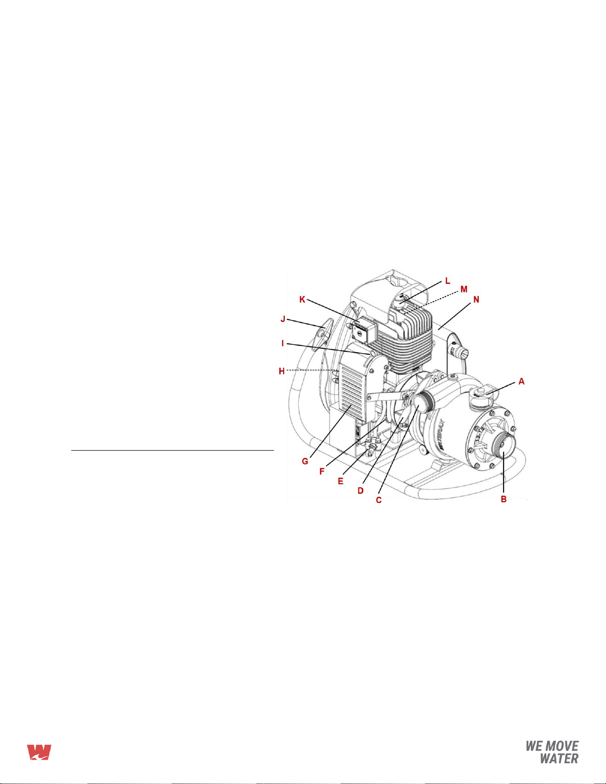
Parts Identification......................................................................................................................................7
Operating MARK-3 Series Pumps..............................................................................................................8
Pre-Operation Checklist.............................................................................................................................8
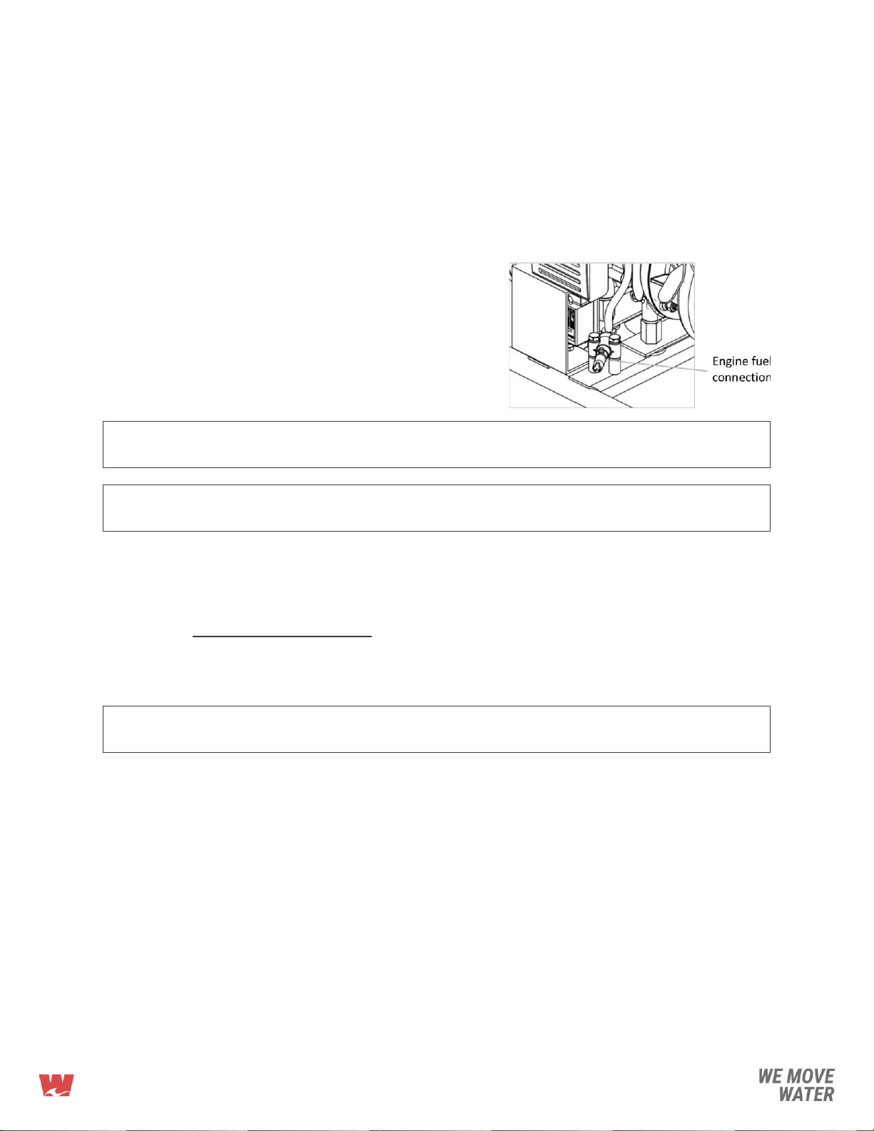
Fuel Supply.................................................................................................................................................8
Pump Connections and Priming...............................................................................................................10
Engine Startup..........................................................................................................................................11
Discharge .................................................................................................................................................12
Shutdown..................................................................................................................................................12
Operating the Digital Overspeed Switch (DOS).......................................................................................12
Cold Weather Operation...........................................................................................................................12
Removing or Attaching the Pump End.....................................................................................................13
Basic Care and Storage...........................................................................................................................13
Troubleshooting........................................................................................................................................15
Service ........................................................................................................................................................17
Carburetor ................................................................................................................................................17
Troubleshooting........................................................................................................................................21
Air Filter....................................................................................................................................................22
Fuel Line...................................................................................................................................................22
Fan Cowl (Housing)..................................................................................................................................23
Pump Clamp.............................................................................................................................................24
Rewind Starter..........................................................................................................................................25
Muffler.......................................................................................................................................................28
Frame.......................................................................................................................................................28
Digital Overspeed Switch (DOS)..............................................................................................................29
Ignition System.........................................................................................................................................30
Engine Overhaul Procedures ...................................................................................................................33
Cylinder ....................................................................................................................................................33
Cylinder Head With Decompression Switch ............................................................................................33
Crankcase ................................................................................................................................................34
Crankshaft Assembly, Pistons and Shims ...............................................................................................35
Engine Tool Kit.........................................................................................................................................35
Piston/Cylinder Matching..........................................................................................................................36
Decarbonising ..........................................................................................................................................37
Deglazing..................................................................................................................................................37
Break-in....................................................................................................................................................37
Disassembly of the Engine From the MARK-3 ........................................................................................39
Disassembly of the Engine.......................................................................................................................39
Reassembly of the Engine .......................................................................................................................39

WATERAX MARK-3 Owner's Manual
03/2016 –Page 4 of 52
Pump End Overhaul Procedures..............................................................................................................42
Pump Tool Kit...........................................................................................................................................42
Disassembly Procedure for Pump End 12-16S .......................................................................................42
Assembly Procedure for Pump End 12-16S ............................................................................................43
Pump Test................................................................................................................................................44
Pump Tool Kit...........................................................................................................................................44
Technical Data............................................................................................................................................45
Pump End.................................................................................................................................................45
Engine ......................................................................................................................................................45
Parts Index..................................................................................................................................................47
Warranty......................................................................................................................................................51

WATERAX MARK-3 Owner's Manual
03/2016 –Page 5 of 52
IMPORTANT SAFETY INSTRUCTIONS
It is recommended that all information provided in this manual be carefully read and
understood before performing any operation of or maintenance to the pump.
The procedures listed in this manual are general operating and maintenance procedures.
They should be taken in addition to any procedures, policies and guidelines established by
the authority having jurisdiction or the apparatus manufacturer. Where conflicts arise, all
parties (authority having jurisdiction, the apparatus manufacturer, and WATERAX Inc.) will
need to be contacted to determine the best resolution. The solution will need to address the
safety of the operator along with the proper performance and life expectancy of the unit.
Personal Safety Advisory
READ THIS MANUAL BEFORE OPERATING YOUR PUMP!
The improper use of the WATERAX pump could result in serious injuries as well as
damage to the pump. This manual contains very important safety information that MUST be
read, understood and followed to safeguard you and your equipment from harm, as well as
specific information on the proper use and care of your engine. Any operator should
familiarize himself with the apparatus and its capabilities before trying to operate the
equipment in an emergency situation. Please read this entire manual before using your
WATERAX pump and follow all Personal Safety Advisories.
Warnings
Always wear eye and ear protection when operating the pump unit.
Do not operate if mentally or physically fatigued.
Always inspect hoses and piping to avoid burst injuries.
Use only pipe, hose, and fittings that are rated at or above the maximum pressure rating
of the pump shown below, or according to what maximum pressure the system was
designed for, whichever is lower.
▪
Maximum Allowable Pressure: 600 PSI (41 bar)
▪
Maximum Allow Pump Intake Pressure: 200 PSI (13.8 bar)
No modifications and/or alterations may be made to the pump. Any such modifications
not only void the pump warranty but can make the unit dangerous to anyone operating
the pump.
Do not operate the pump higher than the maximum rated pressure. Always run the unit
at the lowest pressure required for the application to enhance operator and equipment
safety.
Slowly close valves and use slow close valves wherever possible to prevent danger to
other line operators and to prevent water hammer which could damage the pump and its
piping components.
Relieve all system pressure before doing any service work on the pump.
Never run the pump in a closed or confined area. Exhaust gas contains carbon
monoxide which is poisonous to humans. Avoid inhalation of exhaust gas.
Refuel engine with care. Gasoline is extremely flammable, and gasoline vapor can
explode. Refuel in a well-ventilated area, with the engine stopped.
Be alert and never touch any part of the engine exhaust system while the engine is
running. Always allow enough time, after stopping the unit, for proper cooling of the
muffler and surrounding parts.
Careful not to pinch your fingers around the cooling fan and engine output shaft.

WATERAX MARK-3 Owner's Manual
03/2016 –Page 6 of 52
PREVENTING DAMAGE TO EQUIPMENT
The following recommendations will help avoid damage to your equipment:
Always use the proper fuel mixture.
Do not run the engine at full speed until thoroughly warmed up.
Do not lift strainer out of the water while pump is operating.
Do not run engine with pump disconnected.
Do not run the pump when dry.
Always draft water using a footvalve suction hose strainer.
Check strainer frequently to make sure that it is not clogged with moss, leaves, etc.
Flush the pump with fresh water if the pump has been used to pump salty, brackish,
high mineral content water, water containing debris, or foam injected water. Check that
debris is cleared before using pump again.
Drain pump after final use.
During freezing weather, drain the pump and lines of all water. You can also pour some
antifreeze into the pump and circulate it through the pump and plumbing system.
Pumps should not be operated without water for any extended period of time or without
discharging water. Operating the pump in such a manner can overheat the pump
causing damage to seals, or pump internals.
It is recommended that all fasteners be replaced with genuine WATERAX parts.
INTRODUCTION
About this Manual
This manual contains general operation, care and servicing procedures for the WATERAX
MARK-3 high pressure 4-stage centrifugal pump.
These instructions cover most wildland pump applications. If the application the pump is
being used for does not fall into these general guidelines, consult WATERAX Inc. for any
additional safeguards, operating, or maintenance considerations that may be required.
For full service and maintenance instructions regarding the engine and the pump, please
refer to the Service section.
Please see www.waterax.com additional documentation related to this product such as the
WATERAX product guide, technical notes, news and other updates about WATERAX and
its goods and services.
About the MARK-3
Features
For full specifications and performance curves, see the Product Data Sheet for your pump
end model.
Applications of the WATERAX MARK-3 series include:
Attack line firefighting
Long hose lay for remote watering during firefighting operations
High elevation firefighting in mountainous areas
Accuracy in flow trajectory when structure firefighting
Tandem pumping over long distances
Parallel pumping for higher volumes

WATERAX MARK-3 Owner's Manual
03/2016 –Page 7 of 52
Features and Benefits of the WATERAX MARK-3 series include:
Quick release clamp and swappable pump ends for minimal equipment downtime and
inventory
Sealed bearing to eliminate pump end greasing in the field
Aluminum alloy pump components and anodized parts for lighter weight and greater
resistance to corrosion
Compatible with foam applications
Blister resistant mechanical rotary seal
Comprehensive manuals
The MARK-3 unit has been designed to meet all the requirements of advanced techniques
in forest fire control, including USDA Forest Service Specifications No. 5100-274C.
Considered an emergency rescue equipment, the MARK-3 is exempt from EPA emission
standards under 40 CFR 1054.660.
Parts Identification
A. Priming cap
B. Pump intake (suction)
C. Pump discharge
D. Quick release pump clamp
E. Fuel connection*
F. Engine drain plug
G. Air filter
H. Choke (not shown)
I. Throttle
J. Rewind starter
K. Digital Overspeed Switch (DOS)
L. Spark plug
M. Decompression switch –optional
(not shown)
N. Muffler
* Mercury fuel fitting shown

WATERAX MARK-3 Owner's Manual
03/2016 –Page 8 of 52
OPERATING MARK-3 SERIES PUMPS
Pre-Operation Checklist
Before using your pump, follow this verification procedure:
1. Visually inspect product. When you first receive your MARK-3 pump, inspect the
product and check for any damage. Notify the supplier if any damage is found.
2. Check that all suction and discharge hoses are structurally sound and do not leak.
3. Inspect all safety features and verify that they are in good order before using the pump.
4. Each time you plan to use the pump, check for damage that may have occurred during
previous use. Notify your manager that the equipment requires repair. Remember that
damaged equipment can expose you to safety hazards.
Fuel Supply
Fuel mixture
The MARK-3 is powered by a 185cc two-cycle (two-stroke) engine.
For lubrication, the engine requires a premixed fuel mixture of
gasoline and oil.
GASOLINE: 87 octane unleaded automotive gasoline
(maximum 10% ethanol)
OIL: High quality two-cycle mixing oil with API-TC,
JASO-FD and ISO-L-EGD certification (e.g.,
Amsoil Saber®Professional Synthetic)
FUEL MIX RATIO: 50:1 (gas to oil)
Note:
Not enough emphasis can be placed on the use of correct gasoline and oil mixture. Using
less than the recommended portion of oil will cause overheating and possible engine
damage. Using more than the recommended proportion of oil will cause spark plug
fouling, erratic carburetion, excessive exhaust smoke and rapid carbon deposits.
Note:
This fuel mixture is compatible with both Nikasil and cast iron sleeve cylinder engines. For
engine break-in fuel mixture, refer to the Service section.
Gasoline, octane and ethanol
WATERAX recommends using high quality automotive grade gasoline with a minimum
octane rating of 87 (AKI) and a maximum ethanol concentration of 10% in its fuel mix for
the MARK-3.
It is important to note that gasoline has a shelf life. Depending on storage conditions,
gasoline can go stale in a matter of weeks. Gasoline will deteriorate in three ways:
1. The more volatile components of the gasoline evaporate, leaving behind a heavier
gasoline which can lead to inferior engine performance and a more difficult engine to
start.
2. Certain hydrocarbons in the gas react with oxygen (oxidation) producing new and
harmful compounds. The stale gasoline will smell sour, its color will go dark, and
gummy particles can appear in the gas. This can lead to poor engine performance and
reliability issues with the carburetor.
3. Water contamination, which is normally caused by condensation, can be catastrophic
to the engine. Gasoline containing ethanol is more susceptible to that problem. Ethanol

WATERAX MARK-3 Owner's Manual
03/2016 –Page 9 of 52
is hydrophilic, which means that it tends to draw in moisture. If the water contamination
is severe enough, the ethanol will separate from the gasoline and drop to the bottom of
the fuel tank. Since water and oil do not mix well, this ethanol and water blend can
cause severe engine problems due to the lack of lubrication.
To prevent any damage to the engine, it is highly recommended to only use fresh gasoline.
Gas stabilizers can be used to increase the gasoline’s shelf life; however, it will not restore
back bad gasoline.
Supply recommended fuel to engine
1. Carefully mix the fuel as recommended in
the Fuel Mixture section.
2. Connect fuel supply line to fuel tank.
3. Prime fuel supply line to evacuate air
bubbles.
4. Connect fuel supply line to engine fuel
connection.
5. Pump fuel up to carburetor.
Note:
Careful not to flood the engine when pumping fuel up to the carburetor; gently squeeze
the priming bulb.
Warning:
Ensure that the fuel tank is positioned away and at a safe distance of the muffler to avoid
any potential accident. Always refuel with care.
Flooded engine
Flooding an engine refers to an accumulation of excess fuel in the cylinder and crankcase
due to excessive fuel priming or use of choke. This condition makes the engine nearly
impossible to start without clearing the engine of the excess fuel.
Clearing a flooded engine:
a) Disconnect the spark plug cable and remove the spark plug.
b) Re-connect the spark plug cable to the spark plug. Place the spark plug in contact with
the cylinder head in order to ground the spark plug.
Note:
Failure to ground the spark plug can lead to damage of the CDI ignition coil when cranking
the engine.
c) With both choke and throttle in fully open position, pull starter rope several times until
excess fuel is exhausted.
d) Before reinstalling spark plug, clean and dry electrode and insulator tip.
e) If engine is severely flooded, remove the engine drain plug and drain engine.

WATERAX MARK-3 Owner's Manual
03/2016 –Page 10 of 52
Pump Connections and Priming
1. Connect footvalve strainer to male end of suction hose, then fill suction hose with
water. Connect hose to the pump intake. Use universal hose coupling wrench to tighten
coupling firmly.
Manual Priming:
a) Open the priming cap and fill pump with
water manually.
b) Firmly tighten priming cap.
c) Pump can also be primed by “jerking”
the suction hose until water flows from
the pump’s discharge port.
WATERAX Hand Primer: Connect hand
primer to discharge port or priming port and
pump until water is drawn into the pump.
Firmly tighten priming cap.
2. Connect discharge hose, nozzles, etc. to
pump using universal hose coupling wrench to tighten coupling firmly.
Note:
To provide proper operation of the pump, the suction hose/strainer should be submerged
a minimum of 4 to 6 times the hose diameter into the water source.
DO NOT run pump when dry.
DO NOT allow footvalve strainer to rest on bottom of lake or riverbed. Check strainer
frequently to make sure that it is not clogged with moss, leaves, etc.
DO NOT lift strainer from water while the pump is operating. Use a rope or other means to
keep strainer at proper height, approximately 1 foot (30 cm) below water surface. If
strainer is too close to the water surface, it will draw air and pump may lose prime.
To maintain optimum performance from your pump, follow these recommendations for
selecting and installing your suction hose:
▪
Use the shortest length possible, i.e., place the pump as close to the water as
possible.
▪
Select reinforced crush resistant (non-collapsible) hose.
▪
To avoid air locks, flexible hose should rise gently from the water source to the
suction/inlet port without excessive dips, bumps, sharp angles or rise in its lay.
▪
Footvalve suction strainers should be fitted to prevent foreign matter from entering
the pump.
▪
Where practicable, the installation and use of a suction float will aid in the
performance of your pump, by keeping suction away from the debris on the bottom of
the dam or river.
▪
Ensure that the suction hose is completely submersed.

WATERAX MARK-3 Owner's Manual
03/2016 –Page 11 of 52
Limitations
Several factors can affect the pump’s ability to efficiently draft water. The following
limitations should be taken into account.
▪
Water temperatures above 35 °C (95 °F) can cause noticeable loss in pump
performance.
▪
Barometric pressures below 98 kPa (29 in of Hg) can also cause noticeable loss in
pump performance (specifically elevations >2000 feet above sea level).
▪
Pump performance curves are based off a 5 foot lift (top of water source to impeller
center). Lifts greater than 5 feet will decrease the pump’s performance.
▪
Hose and strainer sizes that are too restrictive can significantly decrease the pump’s
performance.
▪
Intake hose runs in excess of 10 feet can also reduce pump performance.
Engine Startup
1. Power up DOS: crank engine 1-2 times; DOS
LED will blink.
2. Close/engage choke, if engine is cold.
3. Move throttle lever to “START”/”WARM UP”
position (approximately 3 increments from
idle position).
4. If equipped with a decompression switch
(located on the cylinder head), push down the
valve. The valve will close automatically upon
engine startup.
5. Slowly crank engine until resistance (past
compression).
6. Give starter cord a quick and steady pull.
7. Once engine starts, slowly open/disengage choke and allow engine to warm up for a
minimum of 2 minutes before using full throttle.
Note:
The MARK-3 engine is broken-in at the factory. Full throttle operation can be used
provided the engine is given a thorough warm-up period beforehand.
Failure to allow engine to warm up may lead to piston scoring and possibly more
serious engine damage.
Note:
If the rewind starter should break while the unit is on the fire line, the complete rewind
starter assembly can be easily removed, thereby gaining access to a manual starter pulley
which is mounted on the flywheel. Using a rope, wrap around the starter pulley and pull.
Make sure rope wrapping will ensure clockwise rotation (from starter view).

WATERAX MARK-3 Owner's Manual
03/2016 –Page 12 of 52
Discharge Once the pump is primed, and with the engine running, you can begin to discharge water.
a) If pressure does not build in the discharge hose, the pump has not been fully primed.
Prime the pump again
b) The engine works best at wide open throttle. Vary the discharge nozzle opening to
adjust the pump performance.
Important: Do not use a nozzle larger than ½” (12.7 mm).
Note:
Leaving the pump running with all the discharge valves closed is called deadheading the
pump (shut-off). The pump should not be left in this mode for more than a minute.
Leaving in this condition for any length of time will cause the pump to overheat and
damage the pump. To avoid overheating the pump, a re-circulation line (if provided)
should be opened or a discharge line left slightly open to allow fresh water to continue to
enter the pump.
Note:
If the engine throttle is increased and the engine RPM increases without an increase in
pump pressure, the pump may be cavitating. Refer to the limitations listed at the
beginning of this section, and see the troubleshooting section for a verification checklist
and possible solutions.
Shutdown 1. After completing the pump operation, gradually reduce the engine speed and move
throttle to “STOP” position.
2. Allow unit to run for approximately 2 minutes with throttle in this position for proper cool
down.
3. If the pump was last run with foam or water that is salty, brackish or high in mineral
content, flush the pump with fresh water for a minimum of 2 minutes or until the water is
clear.
4. Press and hold the “OFF” button on the DOS until engine shuts down.
5. Drain the pump after final use.
Operating the Digital Overspeed Switch (DOS)
The Digital Overspeed Switch continuously monitors the engine’s speed. In the event of an
overspeed condition which will occur during a loss of prime, the DOS will automatically shut
down the engine to prevent the risk of damage to the engine and pump.
The DOS has an integrated LED for troubleshooting and an OFF switch to manually shut
down the engine.
Important: Cut-out switch must not be made inoperative.
Cold Weather Operation
The pump can be run in below freezing temperatures if certain precautions are taken to
avoid the formation of ice in the pump.
1. After priming the pump, the unit should be run at low speed for a short period of time to
allow all components to warm up before continuing with the remaining operating
procedures.
2. Unless wrapped in a heater, drain the pump of all water if it is stopped for any length of
time. The engine/drive unit should be turned over a few revolutions to make sure all
water has been removed from the pump. Drain the pump priming line if a primer has
been used.
3. After use, drain the pump, manifolds, and lines of all water. You can also pour some
antifreeze into the pump and circulate it through the pump and plumbing system.

WATERAX MARK-3 Owner's Manual
03/2016 –Page 13 of 52
Removing or Attaching the Pump End
The MARK-3 pump has a quick release pump clamp and detachable pump end which facilitates the
servicing of pump units and minimizes down-time in the field by allowing the quick replacement of pump
ends.
To remove pump from engine:
1. Lift pump clamp lever.
2. Release tension-adjusting knob at bottom of
clamp.
3. Remove clamp by tapping bottom end of
each half clamp.
4. Remove pump from engine.
To attach the pump end to the engine:
1. Place flexible buffer coupling on engine
coupling pins.
2. Align flexible buffer coupling holes to pump
end coupling pins and install.
3. Install pump clamp with the lever on the top
side (tension knob at the bottom). Align
clamp locating tabs with pump flange
locating stub.
4. Finger tighten tension knob located at
bottom of clamp to obtain a light pressure on
clamp ring.
CAUTION:
Apply FINGER PRESSURE ONLY to close pump clamp lever. Excessive pressure will
damage or break the clamp link.
Basic Care and Storage
The basic care described in this section does not require any disassembly of the pump. For
any servicing procedures that require removing any part of the pump to access a
component, please see the Service section.
WARNING:
Before doing any maintenance to the pump, always ensure that the
equipment cannot be accidentally started. Follow any apparatus and/or
departmental procedures or guidelines in regards to locking out the
equipment.

WATERAX MARK-3 Owner's Manual
03/2016 –Page 14 of 52
Regular maintenance
Regular maintenance is a schedule of continuous systematic maintenance, designed to
prevent frequent or major breakdowns before they occur.
WARNING:
Maintenance on a fire pump should not be done on the fire line. Always
check your pump unit immediately after use.
After each use:
1. Visually inspect the pump unit.
2. Make sure the mechanical rotary seal is not leaking.
3. Check the pump for external leaks.
4. Check the condition of the flexible buffer coupling. Replace if worn. See instructions for
removing the pump end from the engine using the quick release pump clamp.
5. Check the engine for leaks.
6. Clean any dirt or debris from the pump unit. If necessary, a mild soap and water
solution can be used.
7. Clean air filter.
8. Make sure cooling passages and cylinder fins are clean.
9. Make sure that spark plug is cleaned and has proper gap setting.
10. Check throttle and choke control for proper operation.
11. Check fuel line and fittings for signs of wear, etc.
12. Check starter rope and mechanisms and replace if there are signs of wear.
13. Make sure electronic ignition module is free of debris. Verify condition of wiring and
connectors.
14. Note and report any performance irregularities or any abnormal mechanical sounds.
15. Make sure all necessary tools, spares, and accessories are with the pump.
Long-term storage
1. Completely drain the pump of all water.
2. Drain the carburetor. The engine can be run at idle with the fuel line disconnected until
the engine stops to drain the system.
3. Pour 5 mL (0.17 oz.) of 4-cycle engine oil (any viscosity will do). Slowly crank the
engine to cover the piston rings, cylinder and crankshaft with oil to protect the
components from corrosion. Storage seal fogging oil can also be used.
Important: 2-cycle mixing oil is not recommended as preservation oil; it tends to attract
moisture.
4. Follow any other products, components, apparatus, and departmental procedures
and/or guidelines before placing the unit in storage.

WATERAX MARK-3 Owner's Manual
03/2016 –Page 15 of 52
Troubleshooting
This section provides brief troubleshooting instructions for verifying the set-up and
operation of the pump. Each section describes a condition and lists possible causes along
with a list of items to check to identify the source of the problem and resolve it.
Pump Loses Prime or Will Not Prime
Air Leaks
Verify that suction hose coupling is securely tightened.
Check suction hose gasket.
Check sealing face on pump end suction cover.
Air Trapped in
Suction Line
Check that no part of the suction hose is higher than the pump intake. Pump
suction hose must be laid out with a continuous decline to the water source
fromthe pump intake.
Blocked or
Restricted
Intake Hose or
Strainer
Remove blockage from the intake hose or strainer.
Strainer should not be sitting at the bottom of the water source where debris
canbe picked up. Clean off the strainer and raise to a position that is off the
bottom of the water source (floating strainers are available).
Pump Suction
Lift
Requirements
are Too High
DO NOT attempt pump lifts exceeding 22 feet (6.7 meters) except at elevations
lower than 2000 feet above sea level.
As elevation increases above 2000 feet above sea level, maximum lift heights
will diminish. Check that the lift for the elevation the pump is being required to
operate at is achievable.
Pump Does Not Meet Performance
Incompatible
Suction Hose
Verify suction hose diameter is at a minimum of 2”. Any smaller diameter hose
will negatively impact the pump performance and suction lift.
Gauge or
Instrument
Failure
Check that all gauges are calibrated and that all equipment is in proper
condition. Nozzles with dented edges and bent or damaged pitot tubes will
produce faulty readings.
Blockage
Check hoses and suction strainer; remove any obstructions found.
Check for debris wedged or caught in the impeller, distributor and suction
cover.Remove any obstructions found.
Insufficient
Power to the
Pump
Check engine compression and complete engine repairs if required.
An engine tune up may be needed to bring engine back to peak performance.
An engine will lose approximately 3.5% of its power per every 1000 feet above
sea level. Adjust carburetor accordingly.
Pump Cavitating
Lift Too High
Move pump closer to water source.
Decrease pump’s intake hose length.
Increase pump’s intake hose size.
Restrictions
Check that the bottom of the suction hose at a minimum of 2 feet (0.6 meters)
from the bottom of the water source and correct if necessary.
Check that the bottom of the suction hose/strainer is 4 to 6 times the hose
diameter below the water supply surface level and correct if necessary.

WATERAX MARK-3 Owner's Manual
03/2016 –Page 16 of 52
Engine Does Not Start, Runs Irregularly or Misses
Fuel Supply Tank
Empty
Refill fuel tank.
Carburetor Loose
Tighten nuts and/or
studs.
Fuel Supply Valve
Closed
Open supply valve.
Defective Carburetor
Repair or replace.
Air Vent on Fuel Tank
Closed
Open air vent orunscrew
cap.
Low Speed Mixture Jet
Misadjusted
See “Carburetor”
Defective Fuel Supply
Hose
Replace
High Speed MixtureJet
Misadjusted
See “Carburetor”
Dirty Fuel Strainer
Screen
Clean or replace
Spark Plug Fouled or
Defective
Clean or replace.
Leak in Fuel Supply
System
Tighten or replace
fittings.
No Spark
See “Ignition System”.
Fuel Mixture Too Rich
See “Fuel mixture”.
Wrong Type of Spark
Plug
Use recommended
sparkplug.
Wrong Gasoline in
Fuel Mixture
See “Fuel mixture”.
Air Filter Dirty
Clean or replace.
Water or Dirt in Fuel
System
Drain; flush thoroughly.
Engine Flooded
See “Flooded engine”.
Improper Timing
See “Ignition System”.
Engine Backfires
Spark Plug Fouled or
Defective
Clean or replace.
Defective Carburetor
Repair or replace.
Improper Timing
See “Ignition System”.
Engine Sounds Like a Four-Stroke
Engine Not Warmed
Up Properly
Allow longer warm-up
period.
High Speed Mixture
Jet Misadjusted
See “Carburetor”
Too Much Oil in Fuel
Mixture
See “Fuel mixture”.
Air Filter Dirty
Clean or replace.
Improper Timing
See “Ignition System”.
Engine Does Not Develop Normal Power And/Or Overheats
Wrong Oil
See “Fuel mixture”.
Air Filter Dirty
Clean or replace.
Wrong Gasoline
See “Fuel mixture”.
Muffler Blocked
Replace muffler and/or
spark arrestor
Fuel Mixture Too Lean
See “Fuel mixture”.
Low Speed Mixture Jet
Misadjusted
See “Carburetor”
Fuel Mixture Too Rich
See “Fuel mixture”.
High Speed Mixture
Jet Misadjusted
See “Carburetor”
Cooling System Dirty
Clean cooling system.
Improper Timing
See “Ignition System”.

WATERAX MARK-3 Owner's Manual
03/2016 –Page 17 of 52
SERVICE
This section includes instructions for overhaul and maintenance requiring disassembly of
the 185cc engine and 4-stage pump end model 12-16S.
Note: It is recommended that all fasteners be replaced with genuine WATERAX parts.
Carburetor
Parts breakdown
ID
ITEM NO
DESCRIPTION
QTY
ID
ITEM NO
DESCRIPTION
QTY
-
800152
R-1115 CARBURETOR
-
22
800163*†
R-1009 DIAPHRAGM "SB"
1
1
600540*†
R-1113N GASKET CARBURETOR
1
23
301316
R-1010 DIAPHRAGM COVER
1
2
--
R-1041 MACHINE SCREW WITH
LOCK WASHER
2
24
800162*†
R-1011 FUEL PUMP GASKET
1
3
--
R-1045 BODY
1
25
800164*†
R-1012 FUEL PUMP DIAPHRAGM
1
4
--
R-1040 THROTTLE SHUTTER
1
26
301317
R-1013 ALUMINUM FUEL PUMP BODY
1
5
301314
R-1035 BRASS AND STEEL
THROTTLE SHAFT AND LEVER
1
27
800155†
R-1015 FUEL STRAINER SCREEN
1
6
301327
R-1039 STEEL THROTTLE SHAFT
RETURN SPRING
1
28
800159*†
R-1016 FUEL STRAINER COVER
GASKET
1
7
301325
R-1036 THROTTLE SHAFT CLIP
1
29
301318
R-1017 FUEL STRAINER COVER
1
8
301326
R-1037 LOCK WASHER
1/4 OD X .15 ID
1
30
301319
R-1018 PLATED STEEL MACHINE
SCREW
ROUND SLOTTED
1
9
--
R-1038 MACHINE SCREW
1
31
--
R-1014 MACHINED SCREW WITH
LOCK WASHER
6
10
800550
R-1111 BOLT
1
32
301266
R-1025NA INLET CONTROL
LEVER FULCRUM PIN
1
11
--
THROTTLE LINK LEVER
1
33
800156†
R-1029 INLET TENSION SPRING
1
12
--
R-1110 NUT
1
34
800153*†
R-1046N INLET NEEDLE, SEAT
AND GASKET
1
13
301315
R-1005 BRASS CHOKE SHUTTER
1
35
301333
R-1026 INLET CONTROL LEVER
PINION SCREW
1
14
--
R-1002 CHOKE FRICTION PIN
1
36
800158†
R-1022 MIXTURE SCREW O-RING
2
15
301334
R-1003 PLATED STEEL SPRING FOR
CHOKE FRICTION
1
37
301335
R-1021 SS STEEL FLAT WASHER
1/4"OD X 3/16"ID
2
16
301331
R-1047 BRONZE INLET SEAT GASKET
1
38
301321
R-1020 STAINLESS STEEL
MIXTURE SCREW SPRING
2
17
301322
R-1004 CHOKE SHAFT AND LEVER
1
39
301324
R-1019 PLATED STEEL LOW SPEED
MIXTURE SCREW
1
18
800160*†
R-1001 BODY CHANNEL WELCH PLUG
1
40
301323
R-1030 PLATED STEEL HIGH
SPEED MIXTURE SCREW
1
19
800154†
R-1034 NOZZLE CHECK VALVE
1
41
--
R-1024 IDLE SPEED SCREW SPRING
1
20
800157*†
R-1025N INLET CONTROL LEVER
1
42
--
R-1023 IDLE SPEED SCREW
1
21
800161*†
R-1008 DIAPHRAGM GASKET
1
-
301330*
R-1046N-L LONG NEEDLE, SEAT
AND GASKET
-
* Included in R-1050 MARK-3 Carburetor Repair Kit (600178)
† Included in R-1049A Carburetor Repair Kit (600162)

WATERAX MARK-3 Owner's Manual
03/2016 –Page 18 of 52
Maintenance
The carburetor can be cleaned with a minimum of tools. Before disassembling the carburetor, it is
imperative to flush it clean of dirt by using proper carburetor cleaner.
1. Remove strainer cover retaining screw and plastic cover.
2. Remove strainer cover gasket and strainer screen.
3. Remove screws and fuel pump body.
4. Remove fuel pump diaphragm and gasket.
5. Remove main diaphragm cover plate.
6. Remove main diaphragm and main diaphragm gasket.
7. Remove inlet control lever fulcrum pin, lever and tension spring.
8. Remove inlet needle.
9. With a thin wall 8 mm (5/16”) hex socket, carefully remove the inlet seat. Remove inlet seat gasket.
When reinstalling seat, tighten only to 3-4 Nm [25-35 in-lbs].
10. Remove low speed and high speed mixture screws.
11. The ball check type main nozzle can be removed by tapping it out of the body casting into the venture
with a small punch. A replacement ball check nozzle should be pressed into the casting. The brass
cage should be pressed flush with the metering chamber casting.

WATERAX MARK-3 Owner's Manual
03/2016 –Page 19 of 52
Before reassembling the carburetor (in reverse order as outlined previously), wash all component parts in
carburetor cleaner and blow off with compressed air. The channels in the metering body should be
cleaned by blowing through the low and high speed adjusting orifices. All fuel passages in the three
castings should be cleaned with compressed air.
Do not clean orifices or passages with wires or drills as this might damage and cause incorrect operation
of the carburetor.
When reinstalling O-ring type adjusting screws, lubricate with SAE-30 oil to prevent seizing. Packing
spring type adjustments do not require lubrication.
When reassembling the inlet control lever and spring, make sure that the spring rests in the well of the
metering body and locates on the dimple of the inlet control lever.
Do not stretch spring. Inlet control lever is properly set when flush with floor of diaphragm chamber.
Be certain main diaphragm, gasket and cover casting are carefully fitted over the three small pins cast in
rim at bottom of metering body. The fuel pump gasket, diaphragm and fuel pump body are placed over
similar pins at bottom rim of main diaphragm cover casting. Evenly tighten fuel pump body retaining
screws to insure complete seal of casting separations of both diaphragms.
Frequent cleaning or replacement of the fuel strainer screen will aid satisfactory operation of the
carburetor.
To test the carburetor:
•Pop-off pressure: 8-12 psi
•Reseating pressure: 4-5 psi
Carburetor adjustments
There are three adjustments on the carburetor (see image):
A. Low speed (idle) mixture adjustment screw (“L”)
The low speed mixture screw controls the air-to-fuel
mixture ratio at idle and low speeds.
B. High speed (main) mixture adjustment screw (“H”)
The high speed mixture jet screw controls the air-to-fuel
mixture ratio at high speeds.
C. Idle speed adjustment screw
The idle speed regulating screw controls the idle speed.
Turning the mixture screws clockwise (CW) will close the jets and lean out the mixture (more air, less
fuel). Turning the screws counter-clockwise (CCW) will open up the jets and richen up the mixture (less
air, more fuel).
1. Before starting the pump unit, close both high and low speed adjustment screws by turning CW until
they just touch the seat.
Note:
Turn adjustment screws carefully and gently. Do not force needle into seat; otherwise,
both needle and seat may be permanently damaged.
2. The entry settings are as follows:
•High speed: open jet by turning one (1) turn CCW from fully closed.
•Low speed: open jet by turning one (1) turn CCW from fully closed.
3. Turn idle speed regulating screw until throttle shutter is slightly open.
4. Install a 1/4" [6.35 mm] nozzle tip at the discharge hose.

WATERAX MARK-3 Owner's Manual
03/2016 –Page 20 of 52
5. Start unit. Allow the engine to properly warm up (minimum of 2 minutes) before proceeding with the
adjustments.
Note:
Do not run the engine with the choke engaged for long periods of time to warm up the
engine.
6. When engine is warmed up, return throttle to idle position. Adjust the idle speed regulating screw until
engine idles between 2,000-2,200 rpm for low speed jet adjustment. The pump pressure will be
around 30-35 psi.
7. To adjust the low speed mixture, quickly increase the throttle and observe the engine response
(return back to idle);
•If the engine is running roughly and does not accelerate smoothly, slightly close the low speed jet
by turning the low speed mixture adjustment screw CW to lean out the mixture.
•If the engine hesitates to accelerate, slightly open the low speed jet by turning the low speed
mixture adjustment screw CCW to enrich the mixture.
•Repeat the procedure until the engine reacts smoothly when opening up the throttle.
Note:
The engine at idle should run a bit roughly (richer mixture), but not be on the verge of
“choking” due to an excessive amount of fuel. This will provide adequate lubrication at low
engine speeds where the engine fan cooling is reduced. If the engine runs “too” smoothly
(similar to a 4-cycle engine), this indicates that the mixture is too lean. Adjust
immediately.
8. Increase the speed gradually to full throttle setting. Adjust the high speed mixture:
•Turn the high speed mixture adjustment screw CW and reach the maximum engine speed
(maximum pump pressure). Note: at this point, a slight turn CW would cause the engine speed to
drop resulting in a dangerously lean condition. Adjust immediately.
•To obtain an optimal and safe mixture, open the high speed jet by turning the high speed mixture
adjustment screw ¼ turn CCW from the maximum engine speed setting obtained in last step.
There will be a slight decrease in engine speed (~100-150 rpm) and pump pressure (~5-10 psi).
9. Return back to idle and verify idle speed and low speed mixture adjustment. Correct if necessary. If
low speed mixture was adjusted, increase the speed back to full throttle and adjust the high speed
mixture.
Note:
Do not adjust the low speed and high speed mixture too lean for the sake of
performance; improper adjustment will result in insufficient lubrication, higher
engine temperatures, and premature engine failure.
Note:
It will be necessary to readjust the carburetor when operating the pump at different
altitudes.
A special offset screwdriver is available. It allows for an easy adjustment
of the low speed jet on the MARK-3 carburetor. Item number is 801147.
Other manuals for MARK-3
4
Table of contents
Popular Firefighting Equipment manuals by other brands

Akron
Akron 3462 instructions

babcockdavis
babcockdavis BBC-6601 Installation, operation & maintenance manual

Amerex
Amerex A384T Installation, operating & servicing instructions

Tyco
Tyco PROTECTOSPRAY EA-1 manual

TFT
TFT TORNADO RC Instructions for installation, safe operation and maintenance

FireFlex
FireFlex TOTALPAC2 quick start guide

TFT
TFT Extend-A-Gun XG18 Instructions for installation, safe operation and maintenance

Bosch
Bosch D7030X-S8 installation guide

Ansul
Ansul INERGEN Installation and maintenance manual

POK
POK CRIQUET user manual

Agio
Agio 1902402 manual

Task Force Tips
Task Force Tips BLITZTAC Portable Monitor Instructions for installation, operation and maintenance