manuals.online logo
Brands
  1. Home
  2. •
  3. Brands
  4. •
  5. Tyco Fire Protection Products
  6. •
  7. Firefighting Equipment
  8. •
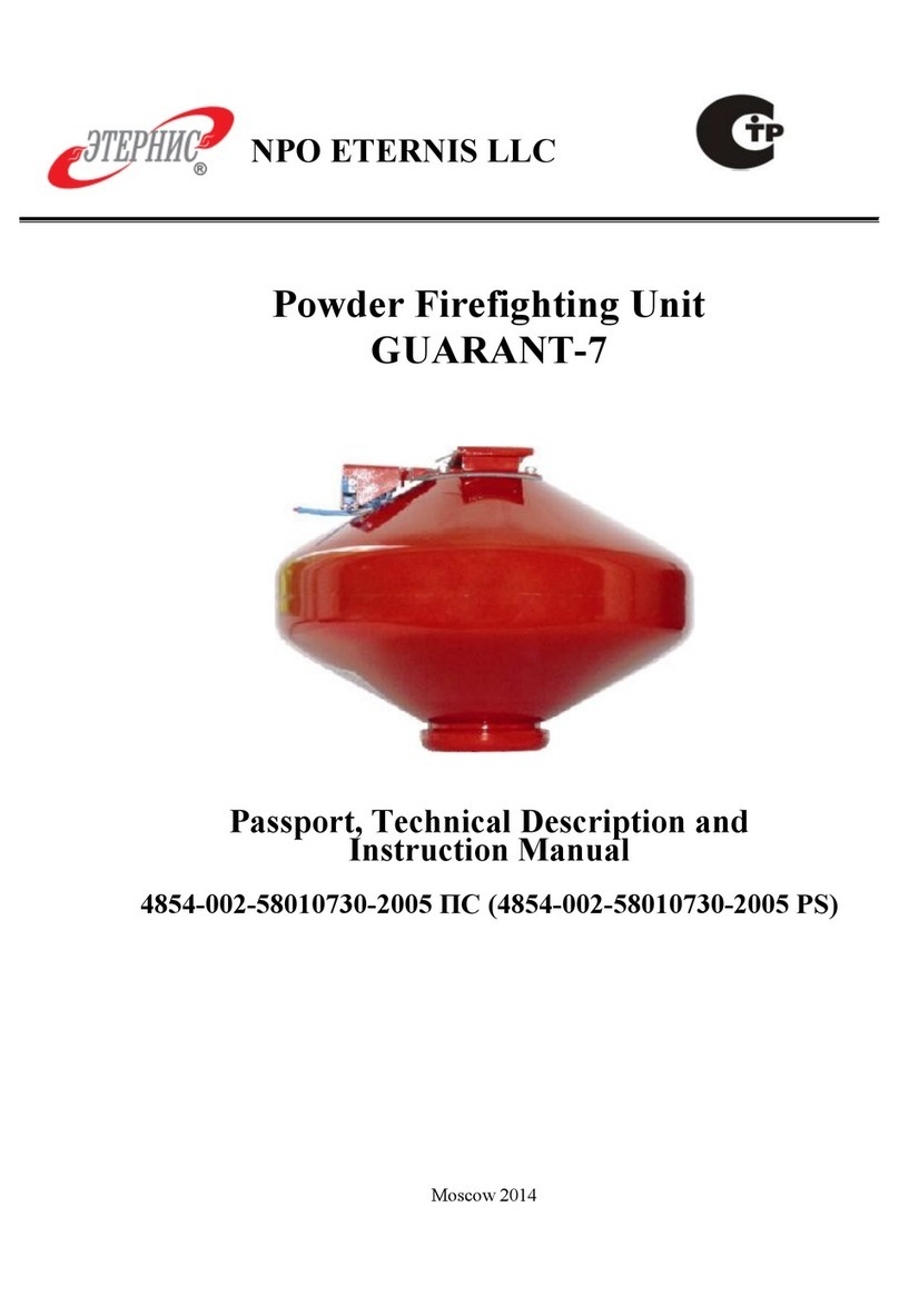
  9. Tyco Fire Protection Products ANSUL PS-150 User manual

Tyco Fire Protection Products ANSUL PS-150 User manual

This manual suits for next models

5

Other Tyco Fire Protection Products Firefighting Equipment manuals

Tyco Fire Protection Products F3200 Instruction sheet

Tyco Fire Protection Products

Tyco Fire Protection Products F3200 Instruction sheet

Tyco Fire Protection Products TY-B Series User manual

Tyco Fire Protection Products

Tyco Fire Protection Products TY-B Series User manual

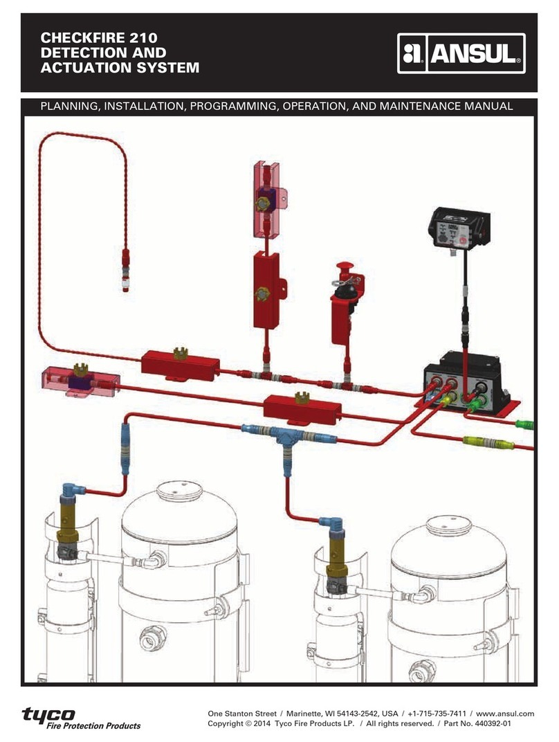
Tyco Fire Protection Products ANSUL CHECKFIRE 210 User manual

Tyco Fire Protection Products

Tyco Fire Protection Products ANSUL CHECKFIRE 210 User manual

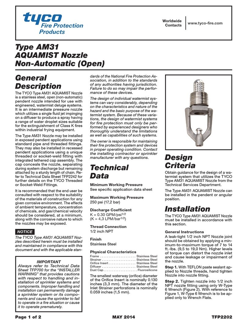
Tyco Fire Protection Products AM31 AQUAMIST Nozzle User manual

Tyco Fire Protection Products

Tyco Fire Protection Products AM31 AQUAMIST Nozzle User manual

Popular Firefighting Equipment manuals by other brands

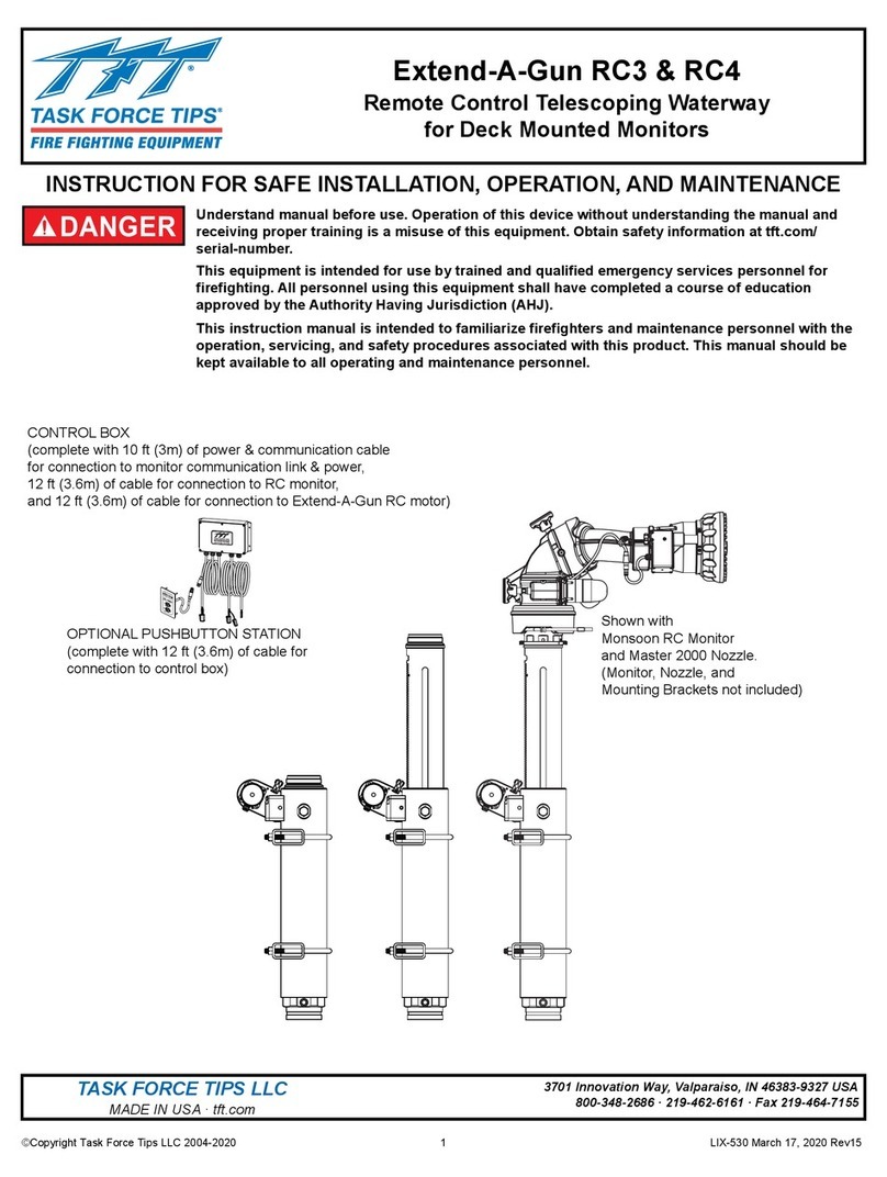
Task Force Tips Extend-A-Gun RC3 INSTRUCTION FOR SAFE INSTALLATION, OPERATION, AND MAINTENANCE

Task Force Tips

Task Force Tips Extend-A-Gun RC3 INSTRUCTION FOR SAFE INSTALLATION, OPERATION, AND MAINTENANCE

Ansul INERGEN Installation and maintenance manual

Ansul

Ansul INERGEN Installation and maintenance manual

Amerex B270 Owner's service manual

Amerex

Amerex B270 Owner's service manual

TFT Working Fire Instructions for installation, safe operation and maintenance

TFT

TFT Working Fire Instructions for installation, safe operation and maintenance

QTAC 85 EMS-C owner's manual

QTAC

QTAC 85 EMS-C owner's manual

Bosch FPC-500-2 Quick installation guide

Bosch

Bosch FPC-500-2 Quick installation guide

Kidde Fire Systems FM-200 ECS Series Design, Installation, Operation, and Maintenance Manual

Kidde Fire Systems

Kidde Fire Systems FM-200 ECS Series Design, Installation, Operation, and Maintenance Manual

Task Force Tips Twister Series Instruction for operation and maintenance

Task Force Tips

Task Force Tips Twister Series Instruction for operation and maintenance

Siemens DMS8000 Operation manual

Siemens

Siemens DMS8000 Operation manual

Tyco K17-231 quick guide

Tyco

Tyco K17-231 quick guide

Amerex B571 Owner's service manual

Amerex

Amerex B571 Owner's service manual

TFT ULTIMATIC Instructions for installation, operation and maintenance

TFT

TFT ULTIMATIC Instructions for installation, operation and maintenance

Task Force Tips Masterstream 4000 ER Automatic INSTRUCTIONS FOR SAFE OPERATION AND MAINTENANCE

Task Force Tips

Task Force Tips Masterstream 4000 ER Automatic INSTRUCTIONS FOR SAFE OPERATION AND MAINTENANCE

ENFORCER 30 Operation and maintenance manual

ENFORCER

ENFORCER 30 Operation and maintenance manual

Plumis Automist Smartscan Hydra Design, Installation, Operation and Maintenance (DIOM) Manual

Plumis

Plumis Automist Smartscan Hydra Design, Installation, Operation and Maintenance (DIOM) Manual

Waterax MARK-3 owner's manual

Waterax

Waterax MARK-3 owner's manual

Dräger Handy Pak operating manual

Dräger

Dräger Handy Pak operating manual

Cooper Lighting Solutions HALO H450FR2ICATD010 instructions

Cooper Lighting Solutions

Cooper Lighting Solutions HALO H450FR2ICATD010 instructions

manuals.online logo
manuals.online logoBrands
  • About & Mission
  • Contact us
  • Privacy Policy
  • Terms and Conditions

Copyright 2025 Manuals.Online. All Rights Reserved.

ANSUL®
FIRE SUPPRESSION SYSTEM
OPERATION AND MAINTENANCE
MANUAL
Part No. 78661-03
ASSEMBLY – OPERATION – MAINTENANCE – INSTRUCTIONS
ANSUL FIRE SUPPRESSION SYSTEM
MODEL PS-150
PS-300
PS-500
PS-1000
PS-2000
PS-3000
TYCO FIRE PROTECTION PRODUCTS, MARINETTE, WISCONSIN 54143-2542
This manual is intended for use with ANSUL Fire Suppression
Systems.
Those who operate, recharge, inspect, or maintain these systems
should read this entire manual. Specific sections will be of
particular interest, depending upon one’s responsibilities.
Fire suppression systems are mechanical devices. They need
periodic care. Inspection, to provide reasonable assurance that
the fire suppression system is fully charged and operable, will vary
from hourly to monthly, based on the needs of the situation.
Inspections should always be conducted at regular intervals.
Maintenance, to provide maximum assurance that the system will
operate effectively and safely, should be conducted at six-month
intervals, or earlier when indicated by an inspection.
Note: The converted metric values in this document are provided for dimensional reference only
and do not reflect an actual measurement.
ANSUL, AUTOMAN, and the product names in this material are marks and/or registered marks.
Unauthorized use is strictly prohibited.
2012-APR-27
78661-03
Copyright © 2012 Tyco Fire Products LP. All rights reserved.
SECTION PAGE/FORM NO./PART NO.
________ _______________________
Assembly 1 – 3
Operation 4
Recharge 5 – 7
Inspection 8
Maintenance 9 – 11
Temperature Correction Charts F-8833, F-8834
Nitrogen Cylinder Valves F-81397
Service and Repair F-8832
Pressure Regulator Test Manual F-78695
AUTOMAN II-C Releasing Device Manual PN17788
AUTOMAN II-C Explosion Proof PN31496
Releasing Device Manual
Parts Lists/Prints
TABLE OF CONTENTS
TO PREPARE THE ANSUL SYSTEM FOR PLACEMENT IN
SERVICE
1. Remove all cord, wrapping, and banding ties. Examine entire
system and component parts for concealed shipping damage
before placement or securement on site.
2. Install AUTOMAN II-C releasing device enclosure on cylinder
rack. Install control unit at desired location. Refer to drawings
(if provided), AUTOMAN II-C Releasing Device Manual, and
control unit manual.
3. If Required: Assemble and connect cylinder actuation line to
outlet on AUTOMAN II-C cartridge receiver. Refer to drawings
(if provided).
4. Install nozzles and distribution piping from hazard(s) to
system. Place a blow-off cap on each nozzle, where used.
Refer to drawings (if provided).
5. Install detection system, alarm(s), and pressure switch(es) (if
provided) to the control unit and/or releasing device. Make
connections from the control unit to the AUTOMAN II-C
releasing device. Refer to manufacturer’s instructions (if
provided), control unit manual, AUTOMAN II-C Releasing
Device Manual, and drawings (if provided).
6. Connect line power source to control unit in accordance with
manufacturer’s instructions and drawings (if provided).
7. When Provided: Install remote manual electric actuation
station(s). Refer to drawings (if provided).
8. When Provided: Connect actuation line tubing and fittings
from each remote actuator to system.
9. Pull ring pin and close RED Tank Valve.
10. Install bursting disc by completing the following steps:
a. Handle the bursting disc carefully. It is a precision product.
Do not bend or kink it. Install only one bursting disc per
tank.
b. Disconnect the union elbow.
c. Disassemble the SILVER bursting disc flange(s) or union.
d. Clean mating surface of bursting disc flange(s) or union.
e. Install bursting disc so that dome is directed away from
tank.
NOTICE
If bursting disc requires replacement, order as
follows:
System Model No. Disc Part No.
________________ ____________
PS-150 1568
PS-300 1568
PS-500 1905
PS-1000 3117
PS-2000 (3 inch) 3117
PS-3000 (3 inch) 3117
PS-2000 (4 inch) 13355
PS-3000 (4 inch) 13355
f. Tighten bursting disc flange(s) or union carefully to prevent
damage to the disc.
g. Reassemble union elbow.
11. Fill agent tank by completing the following steps:
a. Remove fill cap and place funnel in opening.
b. Fill tank to rated capacity with only the ANSUL
extinguishing agent specified on the nameplate.
c. Clean fill opening threads and gasket seating surface.
(Make certain gasket is in place before reinstalling fill cap.)
d. Secure fill cap and hand tighten.
12. Remove safety shipping cap from each nitrogen cylinder, and
make certain that pointer on pressure gauge is in the BLACK
operating range. (Retain shipping cap for future use.)
13. Install each pneumatic valve actuator by completing the
following steps:
a. Extend pneumatic valve actuator rod fully and slide
actuator arm on cross-shaft, engaging pin in hole on Quick-
Opening lever.
ASSEMBLY
Page 1
WARNING
!
Do not install cartridge at this time.
WARNING
!
Do not install cartridge at this time.
WARNING
!
Do not install cartridge at this time.
CAUTION
!
RED Tank Valve must be closed to prevent accidental
agent discharge when assembling the system.
CAUTION
!
All electrical connections should be performed by a
QUALIFIED ELECTRICIAN.
WARNING
!
Make certain safety plug is in place in cylinder valve outlet
before completing the following steps.
CAUTION
!
Flow of agent in piped system is critical. Use only the
ANSUL extinguishing agent specified on nameplate.
Failure to do so may result in system malfunction.
CAUTION
!
Be careful when removing fill cap as tank may have
elevated pressure. Attempting to remove fill cap when
tank has elevated pressure could result in personal
injury or damage to property.
TO PREPARE THE ANSUL SYSTEM FOR PLACEMENT IN
SERVICE  (Continued)
NOTICE
Refer to Nitrogen Cylinder Valve illustration on
F-81397 for additional details.
b. Insert crescent ring into groove on cross-shaft.
c. Insert anchor stud through valve body and actuator pivot
member.
d. Engage and secure cap nut to anchor stud.
14. Remove safety plug from each nitrogen cylinder valve. (Retain
plug for future use.)
15. Connect high pressure hose to each nitrogen cylinder valve
and wrench tighten.
16. Make certain visual inspection seals on each nitrogen cylinder
valve are still intact. Replace any broken or missing visual
inspection seals (Part No. 25940).
17. When Provided: Install cartridge into booster actuator by
completing the following steps:
a. Remove screws at top and bottom, and slide cartridge
guard off.
b. Remove safety shipping cap and weigh cartridge. Replace
if weight is 1/2 ounce (14.2 g), or more, below weight
stamped on cartridge.
NOTICE
Cartridge Part Number is 4893. Order cartridge
under Shipping Part No. 5373 to assure
receiving correct replacement cartridge.
c. Check that puncture pin is fully retracted to assure safe
cartridge installation.
d. Screw cartridge into actuator and hand tighten.
e. Replace cartridge guard and install screws.
18. When Provided: Install cartridge into each remote actuator by
completing the following steps:
a. Pull ring pin and remove cartridge guard.
b. Remove safety shipping cap and weigh cartridge.
c. Replace cartridge if weight is 1/4 ounce (7.1 g), or more,
below weight stamped on models LT-5-R or LT-5-L.
Replace cartridge if weight is 1/2 ounce (14.2 g), or more,
below weight stamped on models LT-20-R or LT-30-R.
NOTICE
If cartridge requires replacement, order under
Shipping Part Number:
Shipping
Model Part No.
______ _______
LT-5-R 6979
LT-5-L 7013
LT-20-R 7032
LT-30-R 5373
d. Raise puncture pin to assure safe cartridge installation.
e. Screw cartridge into actuator and hand tighten.
f. Replace cartridge guard and insert ring pin through guard
into puncture lever link.
g. Seal with visual inspection seal (Part No. 25940).
19. Arm AUTOMAN II-C releasing device by completing the
following steps:
NOTICE
If release will not remain in ARMED position,
check detection system for source of alarm
signal.
a. Arm the releasing device by using the cocking lever (Part
No. 26310).
b. Remove the cocking lever.
c. Manually check releasing device by striking RED push
button.
d. Rearm releasing device by repeating Steps (a) and (b).
20. Install cartridge into AUTOMAN II-C releasing device by
completing the following steps:
a. With releasing device in the armed position, insert ring pin
into puncture pin assembly shaft.
b. Remove safety shipping cap and weigh cartridge. Replace
if weight is 1/2 ounce (14.2 g), or more, below weight
stamped on cartridge.
NOTICE
Cartridge Part Number is 4893. Order cartridge
under Shipping Part No. 5373 to assure
receiving correct replacement cartridge.
ASSEMBLY
Page 2
CAUTION
!
The Quick-Opening lever may be removed slightly
forward, approximately 1/4 inch (6.4 mm), to permit
installation of the anchor stud.
FORWARD MOVEMENT IN EXCESS OF 1/4 INCH
(6.4 mm) MAY RESULT IN ACTUATION OF THE
VALVE. If valve is accidentally actuated, close the valve
by completing Steps 2(b), 2(c), and 2(d) on Page 5.
WARNING
!
Do not place body or head in front of cylinder valve outlet.
If valve is accidentally operated, velocity of unrestricted
escaping gas is forceful enough to cause injury, especially
about the face and head.
WARNING
!
Do not strike “pull” lever when connecting hose to cylinder
valve.
CAUTION
!
Do not attempt to install cartridge before arming release.
WARNING
!
Do not install cartridge at this time.
CAUTION
!
Take all precautions to avoid firing the releasing device
when the ring pin is installed. Firing the release with the
ring pin in place will damage (possibly destroy) the
solenoid.
TO PREPARE THE ANSUL SYSTEM FOR PLACEMENT IN
SERVICE (Continued)
c. Hand tighten cartridge firmly into actuator.
d. Remove ring pin from puncture pin assembly shaft.
e. Close and secure releasing device enclosure cover.
f. Insert ring pin through RED strike button and seal with
visual inspection seal (Part No. 25940), unless
weatherproof enclosure is provided.
21. Return RED tank valve to OPEN position.
22. Insert ring pin through valve handle into bracket and seal with
visual inspection seal (Part No. 25940).
23. To give maximum assurance that the system will operate
effectively and safely, a maintenance examination should be
performed at this time.
24. Record date of placement in service and instruct personnel in
operation of the system.
ASSEMBLY
Page 3
CAUTION
!
Failure to remove ring pin will result in system
malfunction.
CAUTION
!
Do not hit RED button when closing cover.
CAUTION
!
Failure to open RED Tank Valve will result in system
malfunction.
OPERATION
Page 4
TO OPERATE THE ANSUL SYSTEM
Automatic Mode:
The system will function automatically and the alarm will sound (if
provided) upon activation of the detection system.
To Operate Manually:
When Provided: Pull ring pin, push lever on remote actuator.
OR
When Provided: Activate remote manual electric pull station in
accordance with manufacturer’s instructions.
OR
Pull ring pin, push RED strike button on AUTOMAN II-C releasing
device. This is not an option when provided with weatherproof
enclosure.
Alternate Manual Actuation:
If the system cannot be actuated by using any of the above
manual actuation methods:
1. Pull the Quick-Opening operating lever on each nitrogen
cylinder,
OR
2. Turn each cylinder handwheel counterclockwise to full open
position.