PZRacing BOX-E4 Guide

Box Expander 4ch BOX-E4
Technical documentation– v1.0 – 17/11/2014
ntroduction
The 4channel Box Expander is an expansion module for the acquisition of three analogue channels and a digital channel for Start Next and Basic
devices.
nstallation
mportant information regarding installation - READ CAREFULLY
- Keep box and cables a ay from electro-magnetic sources such as coils, sockets, candles, etc.
- Cover the unused connectors of the boxes ith the caps provided.
Install the boxes in areas hich are both accessible and safe. We advise you to fix the boxes to a rigid part of the vehicle (e.g. the frame) using the plastic
Velcro provided. We remind you that you can connect up to three boxes to a single product.
Connections
Before connecting, it is necessary to set the box number through the rotating selector placed on the front in the top left hand corner. The boxes must be
installed in series at the start; it is not necessary to number them in sequence but it is possible to set the box number based on connection
requirements. Do not set the same number on boxes connected to the same device.
The input and output for the communication bet een the t o devices are placed
vertically on the front right part of the box. Connect the extension cable bet een the
equipment and, in sequence, the first box on the OUT connector.
To install any other box, connect the extension cable bet een the N connector of the
previous box and the OUT connector of the next box.
The extension cable included in the package is 50 cm long; if it isn't long enough, use
the optional 50 cm SSBTB050 extension cables.
If you ish to connect the external SS12V100 po er plug, connect in sequence the 5-
pole connector to the N connector of the last box, or cover the N connector of the
last box ith the red cap included in the Start package to protect the plug.
BOX N1
The first connector to the left on box No.1 (in other ords, the rotating s itch set on
number 1) is for the RPM input (RPM); you cannot connect a speed to Box 1's digital
channel. The second connector from the left is for the SSWT100 temperature sensor
(TEMP), if this sensor is not available, leave this entry free. The remaining 4-pole
connectors are generic analogical inputs (A1, A2). The image on the side sho s the
denomination of all the channels.
BOX N2
The first connector on the left of box No. 2 is reserved to the first speed (SPEED1),
hile the others are generic analogical inputs (A3, A4, A5). The image on the side
sho s the denomination of all the channels.
BOX N3
The first connector on the left of box No.3 is for second speed (SPEED2), all the
others are general analogical entries (A6, A7, A8), in the image next to the names of
all the channels.
PZRacing Via de Gasperi 5 – 61032 Fano (PU) Italy - Tel: +39 0721 820434 – Email: [email protected]

Box Expander 4ch BOX-E4
Documentazione tecnica– v1.0 – 17/11/2014
ntroduzione
Il Box Expander 4ch è un modulo di espansione per l'acquisizione di tre canali analogici ed un canale digitale per le strumentazioni Start Next e Basic
nstallazione
Note importanti di installazione – LEGGERE ATTENTAMENTE
- Evitare che il box ed i rispettivi cavi non siano in prossimità di fonti elettromagnetiche come bobine, accensioni, candele, etc
- Coprire i connettori inutilizzati dei vari box con i cappucci in dotazione.
Installare i box in luoghi accessibili ma protetti. Si consiglia di fissare i box in un punto rigido del veicolo (ad esempio il telaio) tramite il velcro plastico
in dotazione. Ricordiamo che è possibile collegare allo stesso prodotto fino a tre box.
Connessioni
Prima di effettuare le connessioni è necessario impostare il numero del box attraverso il selettore rotativo in alto a sinistra posto sul fronte. I box devono
essere installati in serie allo Start, non è necessario numerarli in sequenza ma è possibile impostare il numero del box in base alle esigenze di
collegamento. Non impostare lo stesso numero sui box collegati alla stessa strumentazione.
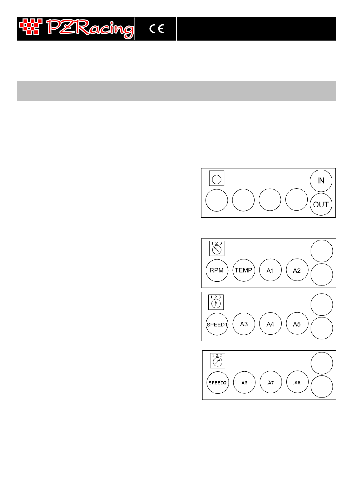
Nella parte anteriore destra del box sono presenti in posizione verticale l'ingresso e
l'uscita della comunicazione tra i dispositivi, collegare la prolunga tra la
strumentazione ed il primo box in cascata sul connettore OUT.
Per installare gli eventuali box successivi collegare la prolunga tra il connettore N del
box precedente ed il connettore OUT del box successivo.
La prolunga all'interno della confezione ha una lunghezza di 50cm, nel caso in cui non
sia sufficiente utilizzare le prolunghe da 50cm SSBTB050 opzionali.
Se si desidera collegare il cavetto per l'alimentazione esterna SS12V100 collegare il
connettore a 5 poli al connettore N dell'ultimo box in sequenza, altrimenti coprire il
connettore N dell'ultimo box con il tappo rosso in dotazione con lo Start per proteggere lo spinotto.
BOX N1
Il primo connettore a sinistra del box N°1 (ovvero con il selettore rotativo impostato
sul numero 1) è riservato per l'ingresso dei giri motore (RPM), non è possibile
collegare una velocità sul canale digitale del Box 1. Il secondo connettore da sinistra è
invece riservato per il nostro sensore di temperatura SSWT100 (TEMP), nel caso non
si disponga di tale sensore lasciare libero questo ingresso. I restanti connettori a 4 poli
sono ingressi analogici generici (A1, A2), nell'immagine accanto la denominazione di
tutti i canali.
BOX N2
Il primo connettore a sinistra del box N°2 è riservato alla prima velocità (SPEED1),
tutti gli altri sono ingressi analogici generici (A3, A4, A5), nell'immagine accanto la
denominazione di tutti i canali.
BOX N3
Il primo connettore a sinistra del box N°3 è riservato alla seconda velocità (SPEED2),
tutti gli altri sono ingressi analogici generici (A6, A7, A8), nell'immagine accanto la
denominazione di tutti i canali.
PZRacing Via de Gasperi 5 – 61032 Fano (PU) Italy - Tel: +39 0721 820434 – Email: [email protected]
Table of contents
Languages:
Popular Extender manuals by other brands

NORAUTO
NORAUTO START PLUS 2223450 instruction manual

Comnet
Comnet FDW1000M/C Installation and operation manual

Teletek electronics
Teletek electronics ECLIPSE WL Installation and programming manual

Attero Tech
Attero Tech Axiom Series user manual

MuxLab
MuxLab 500752 Quick installation guide

Nikrans
Nikrans LCD-1200 installation guide