Valens EVX6-USB-KT-POE User manual

USB & POWER
100m/328ft EXTENDER
Setup Guide
EVX6-USB-KT-POE

Page | 2

Page | 3
TABLE OF CONTENTS
What’s in the box . . . . . . . . . . . . . . . 4
System Overview . . . . . . . . . . . . . . . 5
Electrical specification . . . . . . . . . . . . 6
What’s what . . . . . . . . . . . . . . . . . . . . 7
Logitech Rally Setup . . . . . . . . . . . . . 9
Logitech Meetup Setup . . . . . . . . . .10
Logitech TAP Setup . . . . . . . . . . . . . .11
Generic USB Peripheral Setup . . . . . 12
Troubleshoot . . . . . . . . . . . . . . . . . . .13
Warranty . . . . . . . . . . . . . . . . . . . . . . 14

Page | 4
WHAT’S IN THE BOX
1. Extender –Host Side
2. 48V Power Supply
3. USB-A to USB-C Cable
4. Extender –Device Side
5. USB-C to USB-Cable
6. Optional 12V Power Cable
7. Optional Mounting screws
8. Documentation
Host Side
1.
2.
3.
Device Side
4.
5.
6.
General
7.
8.
1.5m
30cm

Page | 5
SYSTEM OVERVIEW
The EVX6-USB-KT-POE kit extends USB and power over a single standard
CATx cable for distances of up to 100m/328ft. It is a Plug and Play
solution that doesn’t require any driver installation.
The kit includes a Host Side Extender that connects to a Computer via a
USB cable and a Device/Camera Side Extender that connects to the
remote USB peripheral.
The Device/Camera Extender enclosure was specifically designed to fit
the Logitech’s Rally mount. It can also support other Logitech devices as
well as any other standard USB peripheral.
The Device/Camera Extender provides 5V at 2A max or 12V at 1.5A max
power to the remote Device/Camera over a USB-C cable or alternatively
12V at 1.5A max over an optional Power Cable.
100m/328f
Device/Camera
Extender
Host/Computer
Extender
Logitech
Rally

Page | 6
ELECTRICAL SPECIFICATION
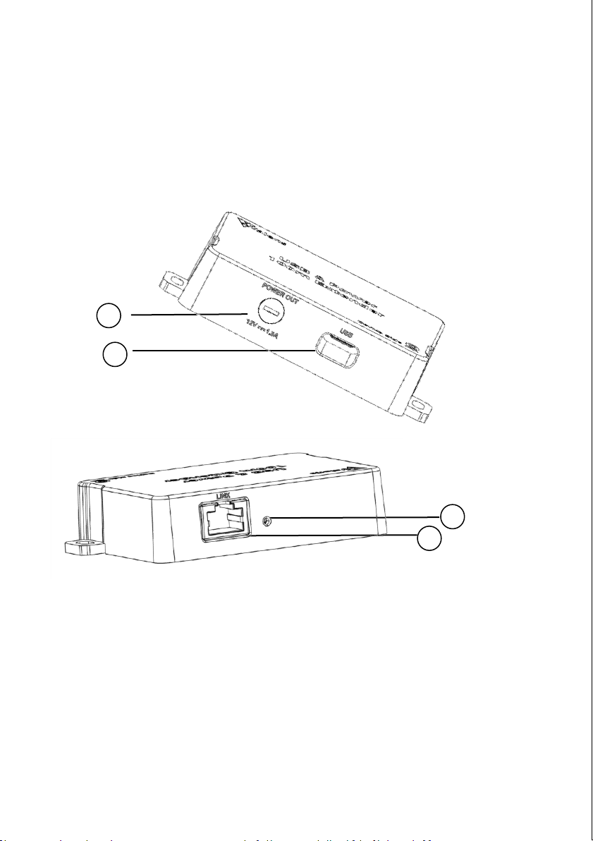
Extender Host Side:
Power input via DC Jack: 48V Typical, 0.75A Max
USB Power Consumption < 2.5W
Operating Temperature: 0-40° Celsius ambient
Extender Device Side:
Power input via RJ45: 48V Typical, 0.75A Max
Power output via DC Jack: 12V +/-0.5V at 1.5A Max
Output Ripple < 300mV
USB-C Power Delivery Voltages support:
•5V @ 2A
•12V @ 1.5A
Operating Temperature: 0-40° Celsius ambient
NOTE
•Link ports (RJ45) on both the Extender Host Side and the Extender
Device Side are considered circuits intended for interconnection
with building wiring installed wholly within the same building
structure (transients are not taken into account).
•The Extender Host Side should be powered with the external
safety approved AC/DC adaptor which is considered Low Power
Supply (LPS).

Page | 7
WHAT’S WHAT
Extender –Host Side
1. Mounting Brackets
2. USB Connection to the Host/Computer
3. Status LED
4. RJ45 Extension Link
5. 48V Input Power
1
2
3
4
5

Page | 8
WHAT’S WHAT
Extender –Device Side
1. Optional 12V Power Output (turn 180 degrees
counterclockwise to remove cover)
2. USB-C Connection to Device/Camera
3. Status LED
4. RJ45 Extension Link
2
1
3
4

Page | 9
CONNECTING YOUR EXTENDER
Logitech Rally Setup
1. Connect the CATx cable from the
Host/Computer Extender to the
Device/Camera Extender
2. Insert the Device/Camera Extender
into the Rally Mount
3. Connect the USB-C to USB-C Cable
from the Device/Camera Extender
to the USB port of the camera
4. Connect the USB-A to USB-C Cable
from the Host Extender to your
computer
5. Connect the power adapter from
the Host Extender to the wall
outlet
6. The status LED will flash when
the computer is turned on and
the extension link is established
successfully

Page | 10
CONNECTING YOUR EXTENDER
Logitech Meetup Setup
1. Connect the USB-C to USB-C Cable
from the Device/Camera Extender
to the USB port of the camera
2. Plug in the provided Power Cable
from the Device/Camera Extender
12V power output (under the
removable cap) to the Meetup
camera
3. Connect the CATx cable from the
Host Extender to the
Device/Camera Extender
4. Connect the USB-A to USB-C
Cable from the Host Extender to
your computer
5. Connect the power adapter from
the Host Extender to the wall
outlet
6. The status LED will flash when
the computer is turned on and
the extension link is established
successfully

Page | 11
CONNECTING YOUR EXTENDER
Logitech TAP Setup
1. Connect the USB-C to USB-C Cable
from the Device/Camera Extender
to the USB port of the TAP
2. Plug in the provided Power Cable
from the Device/Camera Extender
12V power output (under the
removable cap) to the Logitech
TAP
3. Connect the CATx cable from the
Host Extender to the
Device/Camera Extender
4. Connect the USB-A to USB-C
Cable from the Host Extender to
your computer
5. Connect the power adapter from
the Host Extender to the wall
outlet
6. The status LED will flash when
the computer is turned on and
the extension link is established
successfully

Page | 12
CONNECTING YOUR EXTENDER
Generic USB Peripheral Setup
1. Connect the USB-C to USB-C
Cable from the Device/Camera
Extender to the USB port of the
extended device/camera.
2. In case the extended USB Device
requires external power, connect
the provided Optional Power Cable
from the Device Extender 12v
output (under the removable cap)
to your USB Device power input
port
3. Connect the CATx cable from the
Host Extender to the Device/Camera
Extender
4. Connect the USB-A to USB-C Cable
from the Host Extender to your
computer
5. Connect the power adapter from the
Host Extender to the wall outlet
6. The status LED will flash when the
computer is turned on and the
extension link is established
successfully
12V INPUT
12v IN
.

Page | 13
TROUBLESHOOT
Host Side LED Indicator
LED Off –Indicates there is no power to the Extender. Verify the USB cable is properly
connected from the computer to the Host Side Extender.
Lit LED –Indicates the extender has proper power but there is no data link established.
Verify the category cable is properly connected.
Blinking LED –Indicates the link is up and working properly.
Device Side LED Indicator
LED Off –Indicates there is no power supplied to the Device Side Extender. Verify that
the 48V power supply is connected to the Host Side Extender and that the category
cable is properly connected.
Lit LED –Indicates the extender has proper power but there is no data link established.
Verify that the USB Cable from the Computer is properly connected to the Host side
extender and that the category cable is properly connected.
Blinking LED –Indicates the link is up and working.
For more information or assistance, please contact www.valens.com/contact-us

Page | 15

Page | 16
Copyright © 2021 Valens Semiconductors Ltd. All rights reserved
Valens and the Valens Logo are trademarks or registered trademarks of Valens
Semiconductors Ltd. All other trademarks are the property of their respective owners.
Valens assumes no responsibility for any errors that may appear in this manual.
Information contained herein is subject to change without notice.
Table of contents