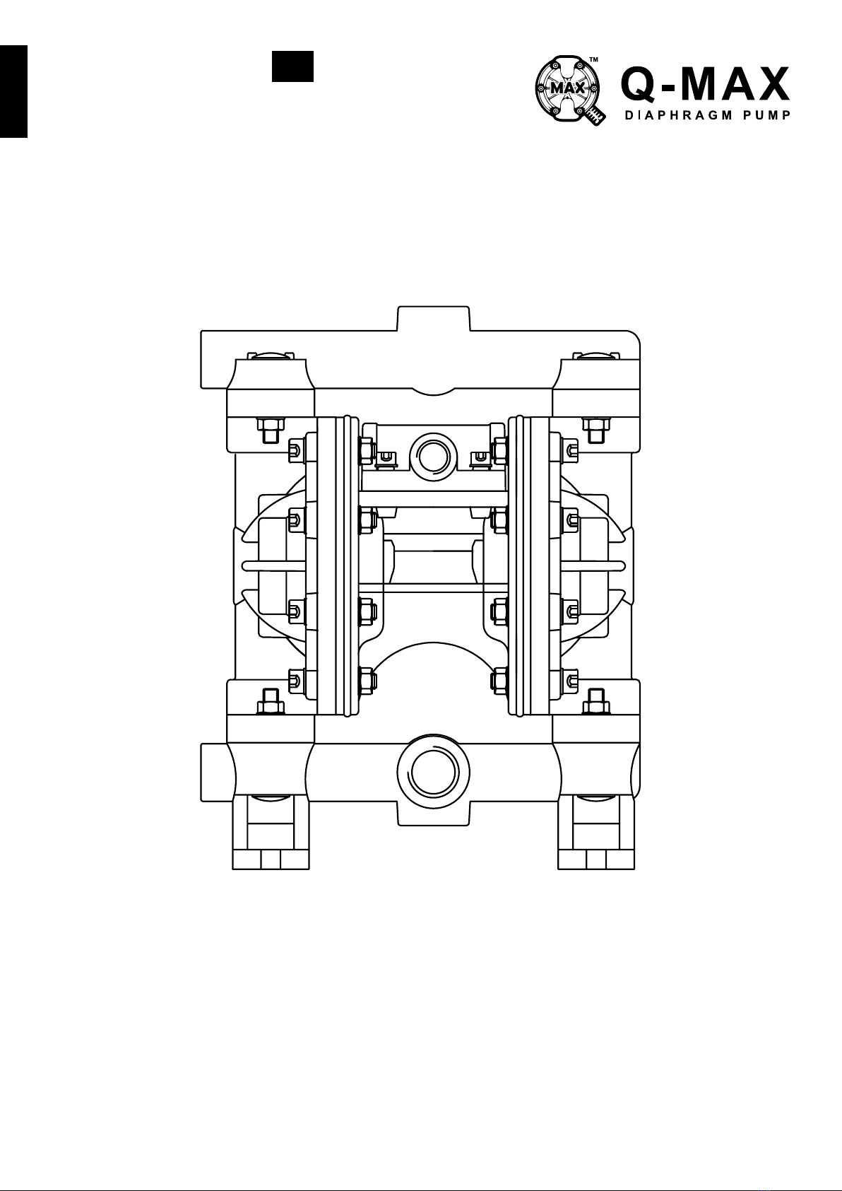
MAX-FLO MY1-25 METAL & NON-METAL - Supreme Performance
Assembly, Installation & Operation Manual | www.qmax.com.my 7
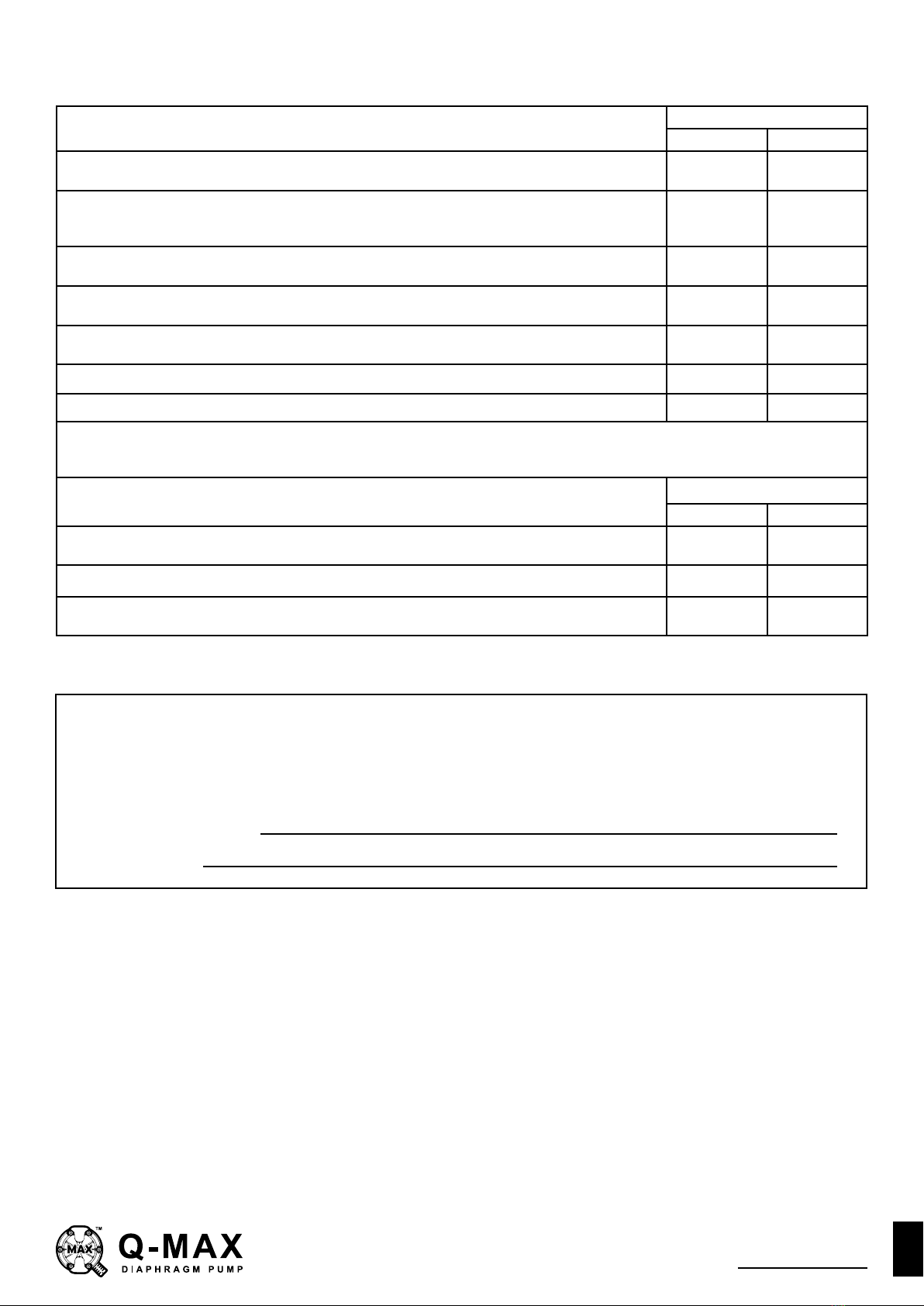
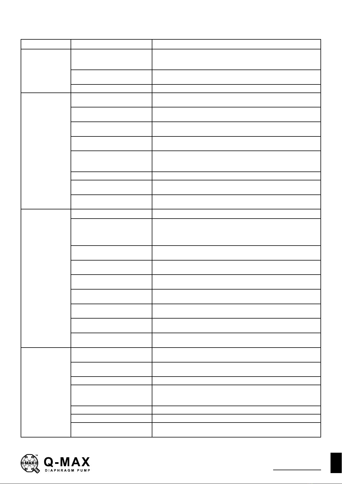
TROUBLESHOOTING GUIDE
Symptom: Potential Cause(s): Recommendation(s):
Pump Cycles
Once
meets or exceeds air supply
Increase the inlet air pressure to the pump. Pump is designed for 1:1
Air valve or intermediate gaskets
installed incorrectly. Install gaskets with holes properly aligned.
Bent or missing actuator plunger. Remove pilot valve and inspect actuator plungers.
Pump Will Not
Operate / Cycle
Pump is over lubricated. Set lubricator on lowest possible setting or remove. Units are designed
for lube free operation.
Check air distribution system. Disassemble and inspect main air distribution valve, pilot valve and pilot
valve actuators.
Discharge line is blocked or
clogged manifolds.
Check for inadvertently closed discharge line valves. Clean discharge
manifolds/piping.
meets or exceeds air supply
Increase the inlet air pressure to the pump. Pump is designed for 1:1
Disassemble pump chambers. Inspect for diaphragm rupture or loose
diaphragm plate assembly.
Pump chamber is blocked.
obstructions.
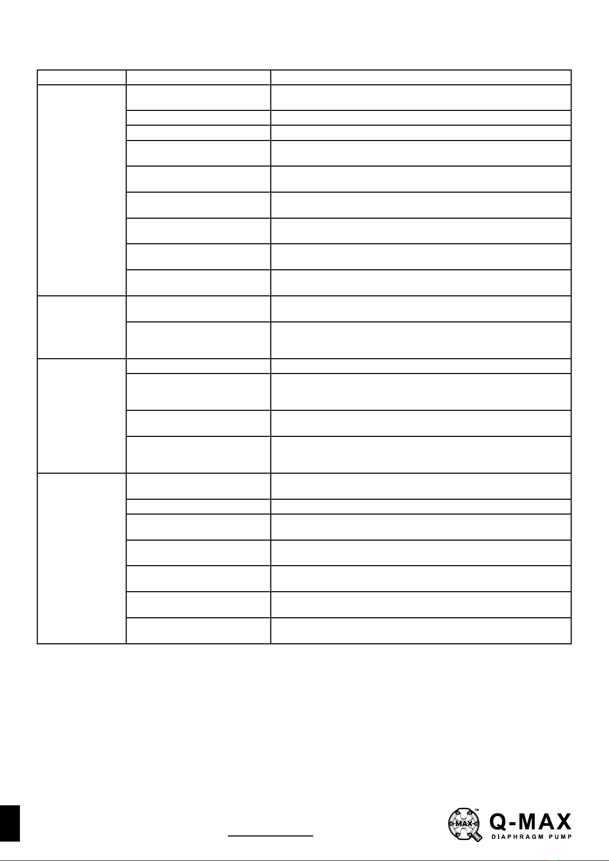
Pump Cycles and
Will Not Prime or
No Flow
Cavitation on suction side.
Check valve obstructed. Valve
sticking.
Disassemble the wet end of the pump and manually dislodge
obstruction in the check valve pocket. Clean out around valve ball cage
and valve seat area. Replace valve ball or valve seat if damaged. Use
heavier valve ball material.
or attacked by product. Check Chemical Resistance Guide for compatibility.
Check valve and/or seat is worn
or needs adjusting.
Inspect check valves and seats for wear and proper setting. Replace if
necessary.
Suction line is blocked.
strainers.
Excessive suction lift.
the pump in most cases.
Suction side air leakage or air in
product. Visually inspect all suction-side gaskets and pipe connections.
Disassemble pump chambers. Inspect for diaphragm rupture or loose
diaphragm plate assembly.
Pump Cycles
Running Sluggish
/ Stalling, Flow
Unsatisfactory
Over lubrication. Set lubricator on lowest possible setting or remove. Units are designed
for lube free operation.
Icing.
drier.
Clogged manifolds.
meets or exceeds air supply
Increase the inlet air pressure to the pump. Pump is designed for 1:1
Cavitation on suction side.
Check the air line size, length, compressor capacity.
Excessive suction lift.
the pump in most cases.