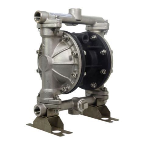
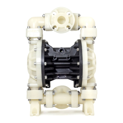
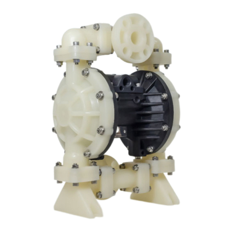
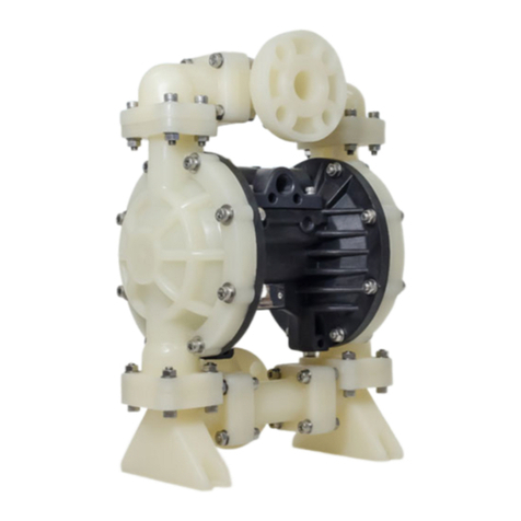
Q-MAX ULTRA-FLO MY3-50 METAL Series User manual

AIR-OPERATED DOUBLE DIAPHRAGM PUMP
Assembly, Installation & Operation Manual
V1.0 2021
MY3 METAL SERIES
ULTRA-FLO 50

ULTRA-FLO MY3-50 METAL - Simplify Your Maintenance
Assembly, Installation & Operation Manual | www.qmax.com.my
2
TABLE OF CONTENTS
1. Read Me First ................................................................................................... 3
Chemical Reaction Disclaimer
Safety Precautions
Caution
2. Pump Specications ........................................................................................ 4
Explanation of Pump Nomenclature
Performance Curve
3. Recommended Installation Guide ................................................................... 6
4. Troubleshooting Guide ..................................................................................... 7
5. Dimension Drawing .......................................................................................... 9
6. Exploded View ................................................................................................. 10
7. Part List ........................................................................................................... 11

ULTRA-FLO MY3-50 METAL - Simplify Your Maintenance
Assembly, Installation & Operation Manual | www.qmax.com.my 3
READ ME FIRST - IMPORTANT INFORMATION
CHEMICAL REACTION DISCLAIMER
The user must exercise primary responsibility in selecting the product’s materials of
The user may consult manufacturer and a manufacturer’s representative/distributor agent to
chemical compatibility.
However neither manufacturer nor a gent shall be liable for product damage or failure, injuries,
with the product’s components.
SAFETY PRECAUTIONS
READ THIS MANUAL COMPLETELY BEFORE INSTALLING AND OPERATING THIS PUMP.
FAILURE TO FOLLOW THESE PRE-CAUTIONS CAN RESULT IN SERIOUS INJURY OR
DEATH.
WARNING: The pumps from this model are not intended to pump fammable or combustible
WARNING: Do not exceed maximum pressure stated on the pump serial number sticker. Pump
exhaust may be loud and contain particles. Wear appropriate ear and eye protection. In the
hazardous or toxic pipe exhaust to appropriate safe area.
WARNING: Chemical Hazard. This pump is used for transferring many types of potentially
dangerous chemicals. Always wear protective clothing, eye protection and follow standard safety
procedures when handling corrosive or personally harmful materials. Proper procedures should
be followed for draining and decontaminating the pump before disassembly and inspection of
the pump. There may be small quantities of chemicals present during inspection.
WARNING: Before maintenance or repair, close the compressed air supply valve, bleed the
pressure and disconnect air line from the pump. Discharge line may be pressurized. Any
pressure must be relieved before service.
CAUTION
1. To help avoid unnecessary damage to the pump, do not allow pump to run dry for long
periods of time.
2. Use only genuine Pump-Fit replacement parts to assure compatible pressure rating and
longest service life.
3.
each use to prevent damage.
4. nstall the pump in a vertical position or the pump may not prime properly.
5. Re-torque all fasteners before operation. Creep of housing and gasket materials may cause
6. Unpack the pump and examine for any signs of shipping damage. If damage is detected,
save the packaging and notify the carrier immediately.

ULTRA-FLO MY3-50 METAL - Simplify Your Maintenance
Assembly, Installation & Operation Manual | www.qmax.com.my
4
PUMP SPECIFICATIONS
EXPLANATION OF PUMP NOMENCLATURE
TECHNICAL SPECIFICATIONS
Max ow (l/min) 690
Max pressure (bar) 8.6
Max air inlet pressure (bar) 8.6
Max solids (mm) 6
Suction lift (mwc)
Dry:
Wet:
6.1
7.62
Fluid ports connection (inch) 2” NPT/BSP
Air inlet port (inch)
Wetted end (weight)
Aluminium
Cast iron
SUS316
33.5kg
61kg
56kg
PERFORMANCE CURVE
0
0
100
80
60
40
20
0
0
1
2
3
4
5
6
7
CAPACITY
Liters per minute
DAEH
U.S. Gallons per minute
BAR
PSI
23.8
25 125
125
50 75 100 150 175 200
250 375 500 625 750
47.4 70.7 94.9 118.1
225
NPSHr
AIR CONSUMPTION IN M³/hr
120
8
30
20
25
10
15
5
9.1
6
7.6
3
4.5
1.5
METERS
FEET
120PSI(8.16 Bar)
100PSI(6.8Bar)
80PSI(5.44Bar)
60PSI(4.08Bar)
40PSI(2.72 Bar)
20PSI(1.36Bar)
AirInletPressure
ULTRA-FLO
50 - 2”
CONNECTION
SIZE
NON-WETTED
PART
A - Aluminium
P - Polypropylene
6 - SUS316
B - Buna-N
N - Neoprene
R - Santoprene
V - Viton
T - PTFE
O - TPO
DIAPHRAGMWETTED PART
A - Aluminium
C - Cast Iron
6 - SUS316
VALVE BALL VALVE SEAT
P - Polypropylene
K - PVDF
B - Buna-N
E - Polyethylene
N - Neoprene
R - Santoprene
V - Viton
T - PTFE
A - Aluminium
6 - SUS316
B - Buna-N
N - Neoprene
R - Santoprene
V - Viton
T - PTFE
O - TPO
//-X X XMY3 X50 X

ULTRA-FLO MY3-50 METAL - Simplify Your Maintenance
Assembly, Installation & Operation Manual | www.qmax.com.my 5
YOUR PUMP INFORMATION
Record the model number and serial number below for future reference. This is important
information when ordering replacement parts or when technical assistance is required.
Your Pump Model #:
Your Serial #:
MATERIAL PROFILE
Materials
CAUTION: Operating temperature limitations are as follows:
Operating Temperature
Max. Min.
Conductive Acetal: Tough, impact resistant, ductile. Good abrasion resistance and low friction
surface. Generally inert, with good chemical resistance except for strong acids and oxidizing
agents.
88°C -29°C
EPDM: Shows very good water and chemical resistance. Has poor resistance to oils and
solvents, but is fair in ketones and alcohols. 138°C -40°C
FKM:
aliphatic, aromatic and halogenated hydrocarbons, acids, animal and vegetable oils. Hot water
177°C -40°C
Hytrel: Good on acids, bases, amines and glycols at room temperatures only. 104°C -29°C
Neoprene:
chemicals, fats, greases and many oils and solvents. Generally attacked by strong oxidizing
acids, ketones, esters and nitro hydrocarbons and chlorinated aromatic hydrocarbons.
93°C -23°C
Nitrile:
resistance. Should not be used with highly polar solvents like acetone and MEK, ozone,
chlorinated hydrocarbons and nitro hydrocarbons.
88°C -23°C
Nylon: 6/6 High strength and toughness over a wide temperature range. Moderate to good
resistance to fuels, oils and chemicals. 82°C 0°C
Polypropylene:
acids and alkali. Attacked by chlorine, fuming nitric acid and other strong oxidizing agents. 82°C 0°C
PVDF:
Excellent for UV applications. High tensile strength and impact resistance. 121°C -18°C
Santoprene:
life. Excellent abrasion resistance. 135°C -40°C
UHMW PE: A thermoplastic that is highly resistant to a broad range of chemicals. Exhibits
outstanding abrasion and impact resistance, along with environmental stress-cracking
resistance.
82°C -37°C
Urethane: Shows good resistance to abrasives. Has poor resistance to most solvents and oils. 66°C 0°C
Virgin PTFE:
104°C -37°C
Maximum and Minimum Temperatures are the limits for which these materials can be operated. Temperatures coupled
with pressure aect the longevity of diaphragm pump components. Maximum life should not be expected at the extreme
limits of the temperature ranges.
Alloy C:
Stainless Steel:
nickel and nickel based alloy castings for general applications. Commonly referred to as 316 Stainless Steel in the pump industry.
Ambient temperature range: -20°C to +40°C
Process temperature range: -20°C to +80°C for models rated as category 1 equipment
-20°C to +100°C for models rated as category 2 equipment
In addition, the ambient temperature range and the process temperature range do not exceed the operating temperature range of
the applied non-metallic parts as listed in the manuals of the pumps.

ULTRA-FLO MY3-50 METAL - Simplify Your Maintenance
Assembly, Installation & Operation Manual | www.qmax.com.my
6
RECOMMENDED INSTALLATION GUIDE
1
2
3
Surge Suppressor
Pressure Gauge
Check Valve
Pipe Connection
Vacuum Gauge
Flexible Connector
Drain Port
Suction
Unregulated Air
Supply to Surge
Suppressor
Filter Regulator
P/N: 020.V107.000
Discharge
Air Inlet
Air Dryer
Flexible Connector
Drain Port
CAUTION: The air exhaust
should be piped to an area
for safe disposition of the
product being pumped, in the
event of a diaphragm failure.
Available Accessories:
1. Surge Suppressor
2. Filter/Regulator
3. Air Dryer
Note: Surge Suppressor and
Piping must be supported
INSTALLATION AND START-UP: Locate the pump as close to the product being pumped as
suction line diameter.
AIR SUPPLY:
achieve desired performance. A pressure regulating valve should be installed to insure air supply
pressure does not exceed recommended limits.
AIR VALVE LUBRICATION:The air distribution system is designed to operate WITHOUT lubrication.
This is the standard mode of operation. If lubrication is desired, install an air line lubricator set to
consumes. Consult the Performance Curve to determine air consumption.
AIR LINE MOISTURE:Water in the compressed air supply may cause icing or freezing of the
exhaust air, causing the pump to cycle erratically or stop operating. Water in the air supply can be
reduced by using a point-of-use air dryer.
AIR INLET AND PRIMING:

ULTRA-FLO MY3-50 METAL - Simplify Your Maintenance
Assembly, Installation & Operation Manual | www.qmax.com.my 7
TROUBLESHOOTING GUIDE
Symptom: Potential Cause(s): Recommendation(s):
Pump Cycles
Once
meets or exceeds air supply
Increase the inlet air pressure to the pump. Pump is designed for 1:1
Air valve or intermediate gaskets
installed incorrectly. Install gaskets with holes properly aligned.
Bent or missing actuator plunger. Remove pilot valve and inspect actuator plungers.
Pump Will Not
Operate / Cycle
Pump is over lubricated. Set lubricator on lowest possible setting or remove. Units are designed
for lube free operation.
Check air distribution system. Disassemble and inspect main air distribution valve, pilot valve and pilot
valve actuators.
Discharge line is blocked or
clogged manifolds.
Check for inadvertently closed discharge line valves. Clean discharge
manifolds/piping.
meets or exceeds air supply
Increase the inlet air pressure to the pump. Pump is designed for 1:1
Disassemble pump chambers. Inspect for diaphragm rupture or loose
diaphragm plate assembly.
Pump chamber is blocked.
obstructions.
Pump Cycles and
Will Not Prime or
No Flow
Cavitation on suction side.
Check valve obstructed. Valve
sticking.
Disassemble the wet end of the pump and manually dislodge
obstruction in the check valve pocket. Clean out around valve ball cage
and valve seat area. Replace valve ball or valve seat if damaged. Use
heavier valve ball material.
or attacked by product. Check Chemical Resistance Guide for compatibility.
Check valve and/or seat is worn
or needs adjusting.
Inspect check valves and seats for wear and proper setting. Replace if
necessary.
Suction line is blocked.
strainers.
Excessive suction lift.
the pump in most cases.
Suction side air leakage or air in
product. Visually inspect all suction-side gaskets and pipe connections.
Disassemble pump chambers. Inspect for diaphragm rupture or loose
diaphragm plate assembly.
Pump Cycles
Running Sluggish
/ Stalling, Flow
Unsatisfactory
Over lubrication. Set lubricator on lowest possible setting or remove. Units are designed
for lube free operation.
Icing.
drier.
Clogged manifolds.
meets or exceeds air supply
Increase the inlet air pressure to the pump. Pump is designed for 1:1
Cavitation on suction side.
Check the air line size, length, compressor capacity.
Excessive suction lift.
the pump in most cases.
ULTRA-FLO MY3-50 METAL - Simplify Your Maintenance
Assembly, Installation & Operation Manual | www.qmax.com.my
8
Symptoms Potential Cause(s): Recommendation(s):
Pump Cycles
Running Sluggish
/ Stalling, Flow
Unsatisfactory
(cont.)
Air supply pressure or volume
exceeds system hd.
Undersized suction line. Meet or exceed pump connections.
Restrictive or undersized air line. Install a larger air line and connection.
Suction side air leakage or air in
product. Visually inspect all suction-side gaskets and pipe connections.
Suction line is blocked.
strainers.
Disassemble pump chambers. Inspect for diaphragm rupture or loose
diaphragm plate assembly.
Check valve obstructed. Disassemble the wet end of the pump and manually dislodge
obstruction in the check valve pocket.
Check valve and/or seat is worn
or needs adjusting.
Inspect check valves and seats for wear and proper setting. Replace if
necessary.
Entrained air or vapor lock in
Purge chambers through tapped chamber vent plugs. Purging the
chambers of air can be dangerous.
Product Leaking
Through Exhaust
Diaphragm failure, or diaphragm
plates loose.
Replace diaphragms, check for damage and ensure diaphragm plates
are tight.
Diaphragm stretched around
center hole or bolt holes.
Check for excessive inlet pressure or air pressure. Consult Chemical
Resistance Chart for compatibility with products, cleaners, temperature
limitations and lubrication.
Premature
Diaphragm Failure
Cavitation. Enlarge pipe diameter on suction side of pump.
pressure.
Move pump closer to product. Raise pump/place pump on top of tank to
Add accumulation tank or pulsation dampener.
Consult Chemical Resistance Chart for compatibility with products,
cleaners, temperature limitations and lubrication.
Incorrect diaphragm plates or
plates on backwards, installed
incorrectly or worn.
Check Operating Manual to check for correct part and installation.
Ensure outer plates have not been worn to a sharp edge.
Unbalanced
Cycling
Excessive suction lift.
the pump in most cases.
Undersized suction line. Meet or exceed pump connections.
Disassemble pump chambers. Inspect for diaphragm rupture or loose
diaphragm plate assembly.
Suction side air leakage or air in
product. Visually inspect all suction-side gaskets and pipe connections.
Check valve obstructed. Disassemble the wet end of the pump and manually dislodge
obstruction in the check valve pocket.
Check valve and/or seat is worn
or needs adjusting.
Inspect check valves and seats for wear and proper setting. Replace if
necessary.
Entrained air or vapor lock in
Purge chambers through tapped chamber vent plugs.
TROUBLESHOOTING GUIDE (CONT.)

ULTRA-FLO MY3-50 METAL - Simplify Your Maintenance
Assembly, Installation & Operation Manual | www.qmax.com.my 9
DIMENSION DRAWING
Dimension Tolerance :±5mm
Pump Model A
(mm)
B
(mm)
C
(mm)
D
(mm)
E
(mm)
F
(mm)
G
(mm)
H
(mm)
I (mm) Weight
(kg)
Standard
muer
Metal
muer
MY3-50
Metal 428 669 256 13 51 631 254 114 320 373
AL: 33.5
CI: 61
SS: 56
B
I
F
G
E
C
A
D
H
Exhaust port
1"NPT
Air inlet
3/4"NPT
Suction port
2"NPT/BSPT
Discharge port
2"NPT/BSPT

ULTRA-FLO MY3-50 METAL - Simplify Your Maintenance
Assembly, Installation & Operation Manual | www.qmax.com.my
10
EXPLODED VIEW
PART LIST
S/N Item Part Number Description Quantity Material(s)
1 1 031.173.000 Air Valve Assembly 1 Aluminum
2 1 031.183.000 1 Aluminum
3 1 031.179.000 1 Stainless Steel
4 1-A 095.109.157 Body, Air Valve 1 Aluminum
5 1-A 095.109.110 Body, Air Valve 1 Stainless Steel
6 1-B 031.139.000 Sleeve and Spool Set 1 Aluminium
7 1-C 132.029.357 Bumper 2 Polyurethane
8 1-D 560.020.360 O-Ring 10 Nitrile
9 1-E 165.127.157 Cap, End 2 Aluminum
10 1-E 165.127.110 Cap, End 2 Stainless Steel
11 1-F 170.032.330 Hex Head Capscrew, 1/4.20*0.75 8 Zinc Plated Steel
12 1-F 170.032.115 Hex Head Capscrew, 1/4.20*0.75 8 Stainless Steel
13 1-G 530.028.550 1 PE
14 1-H 165.096.551 1 Glass Filled PP
15 1-J 706.026.330 Machine Screw 4 Zinc Plated Steel
16 1-J 706.026.115 Machine Screw 4 Stainless Steel
17 2 050.017.354 Ball, Check, Santoprene 4 Santoprene
18 2 050.017.356 Ball, Check, Hytrel 4 Hytrel
19 2 050.017.360 Ball, Check, Nitrile 4 Nitrile
20 2 050.017.363 Ball, Check, FKM 4 FKM
21 2 050.017.364 Ball, Check, EPDM 4 EPDM
22 2 050.017.365 Ball, Check, Neroprene 4 Neroprene
23 2 050.018.600 Ball, Check, PTFE 4 PTFE

ULTRA-FLO MY3-50 METAL - Simplify Your Maintenance
Assembly, Installation & Operation Manual | www.qmax.com.my 11
PART LIST (CONT.)
S/N Item Part Number Description Quantity Material(s)
24 3 070.006.170 Bushing 2 Bronze
25 4 095.110.000 Pilot Valve Assembly 1 Aluminum
26 4 095.110.558 Pilot Valve Assembly 1 Conductive HDPE
27 4-A 095.095.157 Valve Body 1 Aluminum
28 4-A 095.095.558 Valve Body 1 Conductive HDPE
29 4-B 755.052.000 1 Aluminium
30 4-C 560.033.360 6 Nitrile
31 4-D 775.055.000 1 Stainless Steel
32 4-E 560.023.360 3 Nitrile
33 4-F 675.037.080 Retaining Ring 1 Carbon Steel
34 5 114.024.157 Intermediate Bracket 1 Aluminum
35 5 114.024.110 Intermediate Bracket 1 Stainless Steel
36 6 132.035.360 Bumper, Diaphragm 2 Nitrile
37 7 135.034.506 Bushing, Plunger 2 POM
38 8 165.116.157 Cap, Air Inlet Assembly 1 Aluminum
39 8 165.116.110 Cap, Air Inlet Assembly 1 Stainless Steel
40 9 170.052.330 Capscrew, Hex Hd 3/8-16*2.25 16 Zinc Plated Steel
41 9 170.052.115 Capscrew, Hex Hd 3/8-16*2.25 16 Stainless Steel
42 10 170.060.330 Capscrew, Hex Hd 7/16-14*2.00 16 Zinc Plated Steel
43 10 170.060.115 Capscrew, Hex Hd 7/16-14*2.00 16 Stainless Steel
44 11 170.069.330 Capscrew, Hex Hd 5/16-18*1.75 4 Zinc Plated Steel
45 11 170.069.115 Capscrew, Hex Hd 5/16-18*1.75 4 Stainless Steel
46 12 170.006.330 Capscrew, Hex Hd 3/8-16*1.00 4 Zinc Plated Steel
47 12 170.006.115 Capscrew, Hex Hd 3/8-16*1.00 4 Stainless Steel
48 13 171.059.330 Capscrew, Soc Hd 7/16-14*1.25 8 Zinc Plated Steel
49 13 171.059.115 Capscrew, Soc Hd 7/16-14*1.25 8 Stainless Steel
50 14 196.167.157 Chamber, Outer 2 Aluminum
51 14 196.167.010 Chamber, Outer 2 Cast Iron
52 14 196.167.110 Chamber, Outer 2 Stainless Steel
53 15 196.168.157 Chamber, Inner 2 Aluminum
54 15 196.168.110 Chamber, Inner 2 Stainless Steel
55 16 286.020.604 Diaphragm, Overlay 2 PTFE
56 18 286.007.354 Diaphragm 2 Santoprene
57 18 286.007.356 Diaphragm 2 Hytrel
58 18 286.007.360 Diaphragm 2 Nitrile
59 18 286.007.363 Diaphragm 2 FKM
60 18 286.007.364 Diaphragm 2 EPDM
61 18 286.007.365 Diaphragm 2 Neoprene
62 19 360.093.360 Gasket, Air Valve 1 Nitrile
63 20 360.114.360 Gasket, Pilot Valve 1 Nitrile
64 21 360.104.379 Gasket, Air Inlet 1 Conductive Nitrile
65 22 360.105.360 Gasket, Inner Chamber 2 Nitrile
66 23 518.145.156 Manifold, Suction 1 Aluminum
67 23 518.145.156E Manifold, Suction, BSP 1 Aluminum
68 23 518.145.010 Manifold, Suction 1 Cast Iron
69 23 518.145.010E Manifold, Suction, BSP 1 Cast Iron
70 23 518.145.110 Manifold, Suction 1 Stainless Steel
71 23 518.145.110E Manifold, Suction, BSP 1 Stainless Steel

ULTRA-FLO MY3-50 METAL - Simplify Your Maintenance
Assembly, Installation & Operation Manual | www.qmax.com.my
12
PART LIST (CONT.)
S/N Item Part Number Description Quantity Material(s)
72 24 518.146.156 Manifold, Discharge 1 Aluminum
73 24 518.146.156E Manifold, Discharge, BSP 1 Aluminum
74 24 518.146.010 Manifold, Discharge 1 Cast Iron
75 24 518.146.010E Manifold, Discharge, BSP 1 Cast Iron
76 24 518.146.110 Manifold, Discharge 1 Stainless Steel
77 24 518.146.110E Manifold, Discharge, BSP 1 Stainless Steel
78 25 545.005.330 Nut, Hex 3/8-16 16 Zinc Plated Steel
79 25 545.005.115 Nut, Hex 3/8-16 16 Stainless Steel
80 26 545.007.330 Nut, Hex 7/16-14 16 Zinc Plated Steel
81 26 545.007.115 Nut, Hex 7/16-14 16 Stainless Steel
82 27 560.001.379 O-Ring 2 Conductive Nitrile
83 28 612.192.157 Plate, Inner 2 Aluminum
84 28 612.192.010 Plate, Inner 2 Cast Iron
85 28 612.192.110 Plate, Inner 2 Stainless Steel
86 29 612.194.157 Plate, Outer 2 Aluminum
87 29 612.194.010 Plate, Outer 2 Cast Iron
88 29 612.194.110 Plate, Outer 2 Stainless Steel
89 30 612.195.157 2 Aluminum
90 30 612.195.010 2 Aluminum
91 30 612.195.110 2 Stainless Steel
92 31 612.039.157 2 Aluminum
93 31 612.039.010 2 Cast Iron
94 31 612.097.110 2 Stainless Steel
95 32 620.020.115 Plunger, Actuator 2 Stainless Steel
96 33 675.042.115 Ring, Retainer 2 Stainless Steel
97 34 685.058.120 Rod, Diaphragm 1 Stainless Steel
98 35 720.004.360 U.Cup, Rod 2 Nitrile
99 36 722.040.354 Seat, Check Ball 4 Santoprene
100 36 722.040.356 Seat, Check Ball 4 Hytrel
101 36 722.040.360 Seat, Check Ball 4 Nitrile
102 36 722.040.363 Seat, Check Ball 4 FKM
103 36 722.040.364 Seat, Check Ball 4 EPDM
104 36 722.040.365 Seat, Check Ball 4 Neoprene
105 36 722.040.110
4 Stainless Steel
106 36 722.040.150
4 Aluminum
107 36 722.040.550 Seat, Check Ball 4 PE
108 36 722.040.600 Seat, Check Ball 4 PTFE
109 37 900.005.330 Washer, Lock 16 Zinc Plated Steel
110 37 900.005.115 Washer, Lock 16 Stainless Steel
111 38 901.038.330 Washer, Flat 5/16 4 Zinc Plated Steel
112 38 901.038.115 Washer, Flat 5/16 4 Stainless Steel
113 40 560.106.360 8 Nitrile
114 40 560.079.611 8 PTFE Encapsulated FKM
115 40 720.060.600 8 PTFE
116 40 720.060.608 8 Conductive PTFE
117 41 530.033.000 1 Carbon Steel
Table of contents
Other Q-MAX Water Pump manuals

Q-MAX
Q-MAX MAX-FLO MY1-06 NON-METAL Series User manual

Q-MAX
Q-MAX MAX-FLO MY1-25 METAL Series User manual

Q-MAX
Q-MAX MAX-FLO MY1-80 METAL Series User manual

Q-MAX
Q-MAX MAX-FLO MY1-15 METAL Series User manual

Q-MAX
Q-MAX MAX-FLO MY1-40 METAL Series User manual

Q-MAX
Q-MAX MAX-FLO MY1-50 METAL Series User manual