Qianglongsheng Electronic Technology MCD-DEMO-II User manual

DEMO-IICopyright ofQianlongshengElectronicsTechnology(Shenzhen)Co.,Ltd.
Page1 of33
Chapter1:MCD-DEMO-II DevelopmentBoardSystemIntroduction
1.1Product Overview------------------------------------------------------------------------------------------------------------------------2
1.2BoardResourceIntroduction---------------------------------------------------------------------------------------------------------2
1.3Product Schematics---------------------------------------------------------------------------------------------------------------------4
Chapter2:MPLAB IDEIntegrated DevelopmentEnvironment
2.1MPLAB Installation ----------------------------------------------------------------------------------------------------------------------5
2.2MPLAB SimpleApplication -----------------------------------------------------------------------------------------------------------5
2.2.1CreateaSimpleProject-------------------------------------------------------------------------------------------------------------5
2.2.2ProgramDebugging------------------------------------------------------------------------------------------------------------------7
Chapter3:Use ofOn-lineDebuggerMCD2
3.1Get toKnowMCD2---------------------------------------------------------------------------------------------------------------------9
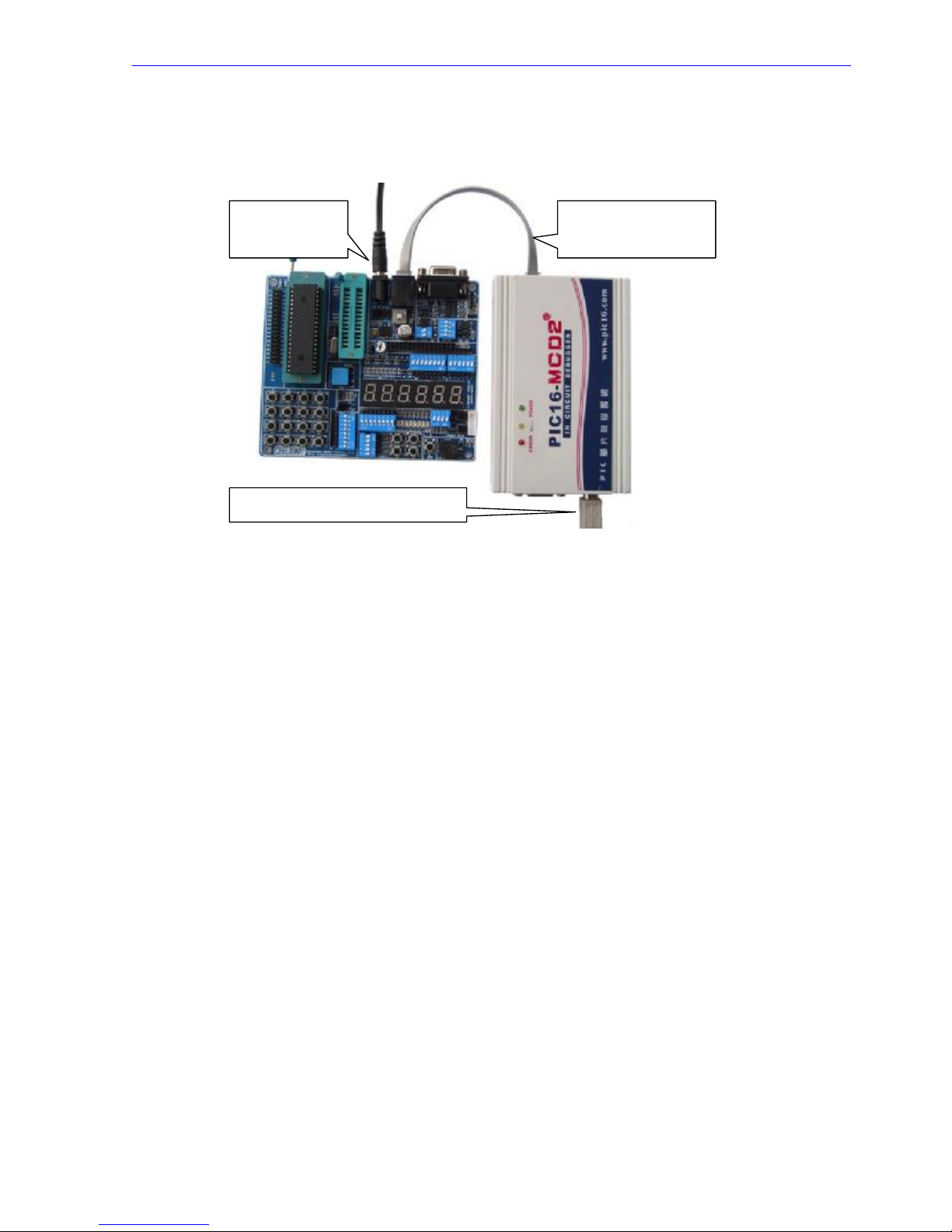
3.2MCD2Connection----------------------------------------------------------------------------------------------------------------------10
3.3MCD2FAQ --------------------------------------------------------------------------------------------------------------------------------12
Chapter4:DEMO-II System FunctionalModulesDetails
4.1All I/O ExternalOutput Module-------------------------------------------------------------------------------------------------------13
4.2ChipSocketandClock Selection----------------------------------------------------------------------------------------------------14
4.3PowerModule-----------------------------------------------------------------------------------------------------------------------------15
4.44*4MatrixKeyboardModule-----------------------------------------------------------------------------------------------------------16
4.5Simulation Interfaceand Reset Button---------------------------------------------------------------------------------------------17
4.6RS232Module----------------------------------------------------------------------------------------------------------------------------18
4.7DS18B20Module------------------------------------------------------------------------------------------------------------------------19
4.8SPICommunicationModule----------------------------------------------------------------------------------------------------------20
4.9IICCommunicationModule -----------------------------------------------------------------------------------------------------------21
4.10LCD12864and1602LCDModule ------------------------------------------------------------------------------------------------22
4.11A/DConverterModule-----------------------------------------------------------------------------------------------------------------23
4.12RemoteControlReceiver&DecoderModule----------------------------------------------------------------------------------24
4.13Six-digitalDisplayModule------------------------------------------------------------------------------------------------------------25
4.148play-in-turnLight Module-----------------------------------------------------------------------------------------------------------26
4.15StepperMotorModule-----------------------------------------------------------------------------------------------------------------27
4.16BeeperModule--------------------------------------------------------------------------------------------------------------------------28
4.17Independent Keyand ExternalInterruptModule------------------------------------------------------------------------------29
Chapter5:PracticeofDEMO-II DevelopmentBoard---------------------------------------------------------------------------30
Appendix1:Packing Listand Contact----------------------------------------------------------------------------------------------33

DEMO-IICopyright ofQianlongshengElectronicsTechnology(Shenzhen)Co.,Ltd.
Page2 of33
MCD-DEMO-II DevelopmentBoardSystemIntroduction
1.1ProductOverview
MCD-DEMOPICDEVELOPMENTBOARD II (hereinafterreferred toDEMO-II)isamultifunctionalPIC
microcontrollerdevelopmentplatformwhichhasbeen carefullydesignedanddevelopedbyQianglongshengElectronic
Technology(Shenzhen)Co., Ltd.basedonmanyyears developmentexperienceand theoriginalDEMO-I. It integrated
the common externalresourcesandsimulationinterfaces.Associatingwiththe dataandalargenumberof examplesof
programsthatourcompanyprovides,youwill beable tofullymastermicrocontrollerprogrammingtechnologyin a
shortesttime. Particularlyit issuitableforselflearningformicrocontrollerbeginnersaswell aselectroniclovers.
DEMO-II developmentboardtogetherwithonlinedebuggerPIC16-MCD2produced byourcompany,ortogetherwith
online debuggerICD2producedbyMicrochip, canbringyouamultiplierbenefit.
Thefollowingpointsmayillustratehowyourchoicewaswise.
uRichboardresources
uOptimizedmodulardesign
uSuperiorproductiontechnology
uRichsupporting examples
uLowsellingprices
uComprehensivetechnicalguidance
uPerfect afterservice
1.2Board ResourceIntroduction
1)I/O externaloutput
2)40P/28Pchip socket
3)Powermodule
4)Simulationinterface
5)RS232communicationmodule

DEMO-IICopyright ofQianlongshengElectronicsTechnology(Shenzhen)Co.,Ltd.
Page3 of33
6)DS18B20module
7)SPI communicationmodule
8)IICcommunicationmodule
9)LCD12864and1602LCDmodule
10)A/Dconvertermodule
11)Resetbutton
12)4*4matrixkeyboardmodule
13)Remotecontrolreceiver&decodermodule
14)six-digitaldisplaymodule
15)8on-in-turnlight module
16)Steppermotormodule
17)Beepermodule
18)Externalinterruptinputmodule
19)Independentbutton module

DEMO-IICopyright ofQianlongshengElectronicsTechnology(Shenzhen)Co.,Ltd.
Page4 of33
1.3ProductsSchematic
12345678
A
B
C
D
87654321
D
C
B
A
Title
Number RevisionSize
A3
Date: 10-Apr-2008 Sheetof
File: E:\cxq\mcd-demoii_sl\demo.DDB DrawnBy:
R44
470R
VR1
1K
VCC
R1IN
13
R2IN
8
T1IN
11
T2IN
10
C1+
1
C1-
3
GND
15
C2- 5
C2+ 4
T2OUT 7
T1OUT 14
R2OUT 9
R1OUT 12
V+ 2
V- 6
VCC 16
U7
MAX232
1
6
2
7
3
8
4
9
5
J12 DB9
RX
TX
C16
105
C17
104
VCC
C14
105
C15
105
R37330R
R36 330R
R C6
R C7
R38 330R TX
R35330R
RX
C12
105 C13
105
VO1
RA5
RA4
RA3
RA2
RA1
RA0
CS
1
CLK
2
DI
3
DO
4VSS 5
DRG 6
NU 7
VCC 8
U6
93CXX SPIEEPROM
C11
104P
VCC
1
2
3
4
8
7
6
5
S7
RC2
RC3
RC5
RC4
SDA
5
SCLK
6
WR
7
VDD
8
GND 4
NC 3
NC 2
NC 1
U5
24CXX I2CEEPROM
RC4
RC3
VCC
GND
1DQ
2VDD
3
U8
DS18B20
R34
10K
C20
104P
VCC
DS18B20
RA0
RA1
RA2
RA3
RA4
RA5
DIG1
DIG2
DIG3
DIG4
DIG5
DIG6
RD0
RD1
RD2
RD3
RD4
RD5
RD6
RD7 1
2
3
4
5
6
7
8
9
10
11
12
13
14
15
16
S6 R18
8-680R
R19
R20
R21
R22
R23
R24
R25
Q1
8550 Q2
8550
R26
10K R27
10K
Q3
8550 Q4
8550 Q5
8550 Q6
8550
R28
10K R29
10K R30
10K R31
10K
DIG2 DIG1 DIG4 DIG3 DIG6 DIG5
VCC
F
8
D 1G 1
1 0
D
1
E
3
D 1G 2
5
C
4
D P
2
G
9
A
7
B
6
D7
LED(SEG)420
F
8
D1G1
10
D
1
E
3
D1G2
5
C
4
DP
2
G
9
A
7
B
6
D8
LED(SEG)420
F
8
D1G1
10
D
1
E
3
D1G2
5
C
4
DP
2
G
9
A
7
B
6
D9
LED(SEG)420
A
B
C
D
E
F
G
DP
A
B
C
D
E
F
G
DP
A
B
C
D
E
F
G
DP
7-SEGMENTDISPLAY
RS232COMMUNICATION
VCC
R D 0
R D 1
R D 2
R D 3
R D 4
R D 5
R D 6
R D 7
+5V
1
GND
2
OUT
3
U9
1838V
C21
104P
VCC
R43 100
R42
100
REMOTECONTROL
VEE
R32 4K7
R33 4K7
VCC
1
2
3
J15
VCC
1
24
3
S8
C10104P
VCC
VCC
LCD1602
VCC
RA1
RA2
RA3
RD0
RD1
RD2
RD3
RD4
RD5
RD6
RD7
1
2
3
4
5
6
12
11
10
9
8
7
S5
U10
BUZZER
Q8
8050
R39
10K
R40
10k
VCC
A/DINPUT
BUZZER
MCD-DEMO-IIBOARD(1)
VSS
1
VDD
2
VO
3
RS
4
R/ W
5
E
6
DB0
7
DB1
8
DB2
9
DB3
1 0
DB4
1 1
DB5
1 2
DB6
1 3
DB7
1 4
BLK
1 5
BLA
1 6
J10 L602LCD
12864LCD
VCC
1
GND
2
VO
3
D/I
4
R/W
5
E
6
RD0
7
RD1
8
RD2
9
RD3
10
RD4
11
RD5
12
RD6
13
RD7
14
PSB
15
NC
16
RST
17
VEE
18
A
19
K
20
J11
12864LCD
R45
680R
1
2
J17
RC2
1
2J151
2
J16
1
2
J17
RA2
1
2
J19
1
2
J18
RA0
RA1
1
2
3
4
5
6
J9
1
2
3
4
8
7
6
5
S4
SWDIP-4
RA0
RA1
RA2
RA3
2302
2302
2302
2302
R49
3K
R50
3K
R51
3K
R52
3K
D10
IN4007
D11
IN4007
D12
IN4007
D12
IN4007
VCC
VCC
STEPPERMOTOR
F1
0.3A
A0
Zhongruntian
2 1
1
2
3
4
5
6
1
2
3
4
5
6
7
8
123456
A
B
C
D
654321
D
C
B
A
Title
Number RevisionSize
B
Date: 10-Apr-2008 Sheetof
File: E:\cxq\mcd-demoii_sl\demo.DDB DrawnBy:
RA0
2
RA1
3
RA2
4
RA3
5
RA4/T0CKI
6
RA5/SS
7
RB0/INT
33
RB1
34
RB2
35
RB3
36
RB4
37
RB5
38
RB6
39
RB7
40
RC1/T1OSI/CCP2 16
RC0/T1OSO/T1CKI 15
RC2/CCP1 17
RC3/SCK/SCL 18
RC4/SDI/SDA 23
RC5/SDO 24
RC6/TX/CK 25
RC7/RX/DT 26
RD0/PSP0 19
RD1/PSP1 20
RD2/PSP2 21
RD3/PSP3 22
RD4/PSP4 27
RD5/PSP5 28
RD6/PSP6 29
RD7/PSP7 30
RE0/RD//AN5
8
RE1/WR/AN6
9RE2/CS/AN7 10
VSS
12
VSS
31
MCLR/VPP
1OSC1/CLKIN
13 OSC2/CLKOUT 14
VDD 11
VDD 32
U2
RA0
RA1
RA2
RA3
RA4
RA5
RB0
RB1
RB2
RB3
RB4
RB5
RB6
RB7
RE0
RE1 RE2
RD7
RD6
RD5
RD4
RD3
RD2
RD1
RD0
RC7
RC6
RC5
RC4
RC3
RC2
RC1
RC0
VCC
VPP
OSC1
RA0/AN0
2
RA1/AN1
3
RA2/AN2
4
RA3/AN3/VREF
5
RA4/T0CKI
6
RA5/AN4/SS
7
RB0/INT
21
RB1
22
RB2
23
RB3
24
RB4
25
RB5 26
RB6 27
RB7 28
RC0/T1OSO/T1CKI 11
RC1/T1OSI 12
RC2/CCP1 13
RC3/SCK/SCL 14
RC4/SDI/SDA 15
RC5/SDO 16
RC6 17
RC7 18
VSS
8
VSS
19
MCLR/VPP
1OSC1/CLKIN
9OSC2/CLKOUT 10
VDD 20
U3
RC0
RC1
RC2
RC3
RC4
RC5
RC6
RC7
RB7
RB6
RA0
RB5
RA1
RA2
RA3
RA4
RA5
RB0
RB1
RB2
RB3
RB4
VPP
OSC1
C9
104P
VCC
40PIN
1
2
3
J3 RC/XT
1
2
3
J4 RC/XT
C7
22P
R4
4K7
VCC
OSC2
OSC1
Y1
4.000MHZ
C5
22P
C6
22P
C8
1O4P
R10 470
R11470
R12470
R13 470
R14470
R15 470
R16470
R17470
LED2
RC0
LED3
RC1
LED4
RC2
LED5
RC3
LED6
RC4
LED7
RC5
LED8
RC6
LED9
RC7
RC0
RC1
RC2
RC3
RC4
RC5
RC6
RC7
1
2
3
4
5
6
7
89
10
11
12
13
14
15
16
S2
8*LED
J1
DC9VIN
D4 IN4007
D1 IN4007
D2 IN4007
D3 IN4007
C1
104P C2
470U/16v
1 3
2
V V
GND
IN OUT
U1
78M05
C3
47U/6.3v
C4
104P
POWERSUPPLY
OSC2
VCC
R2
470R
K1 RESET
1
2
3
4
5
6
J2
ICSP
R3
47K
VPP
VCC
RB7
RB6
RB3
VCC
R1
2K2
LED1
POWER
VCC
RB0
RB1
RB2
RB3
PUSHBUTTONS
K2 RB1
K3 RB2
K4 RB3
K5 RB4
R6
1K
R7
1K
R8
1K
R9
1K
1
2
3
4
5
10
9
8
7
6
S1
RB4
K1 RB0
R5
1K
S11 POWER
DIRECT
MCD-DEMO-IIBOARD(2)
1
2
3
4
5
6
7
8
J6
1
2
3
4
5
J5
1
2
3
4
5
6
7
8
J7
K4K3K2K1
K8K7K6K5
K12K11K10K9
K16K15K14K13
1
2
3
4
5
6
7
8
16
15
14
13
12
11
10
9
S3
4X4KEYMATRIX
RC0
RC1
RC2
RC3
RC4
RC5
RC6
RC7
1
2
3
4
5
6
7
8
9
J8
10K*8
VCC
OSC2
1
2
3
4
5
6
7
8
9
10
11
12
13
14
15
16
17
18
19
20
21
22
23
24
25
26
27
28
29
30
31
32
33
34
35
36
J16
RD0
RD1
RD2
RD3
RD4
RD5
RD6
RD7
RB0
RB1
RB2
RB3
RB4
RB5
RB6
RB7
RC0
RC1
RC2
RC3
RC4
RC5
RC6
RC7
RE2
RE0
RE1
RA0
RA1
RA2
RA3
RA4
RA5
28PIN
RESET&ICSP
VPP
PORT ACCESS A0
Zhongruntian
2 2

DEMO-IICopyright ofQianlongshengElectronicsTechnology(Shenzhen)Co.,Ltd.
Page5 of33
Chapter2MPLAB IDEIntegratedDevelopmentEnvironment
MPLAB IDE(hereinafterreferredasMPLAB) isthepowerfulsoftwareintegrateddevelopmentenvironmentprovided
byMicrochipforitsPICmicrocontroller.Itallowsuserstocreate,record, editandcomplyprogramsofmicrocontrollersof
PICseriesontheirowncomputersystems,and itevencanachievesdynamicsimulationanddebuggingandrunlike
virtualexercises.
2.1Theinstallation ofMPLAB
MPLABiscompletelyfree softwareofferedbyMicrochip.You canobtainthelatestinstallationfilesthrough the
followingtwo ways.
1),Visitourwebsite: www.pic16.com
2),Visit Microchipswebsite: www.microchip.com
Afterdownloading thefiles,youonlyneedtousecompression/decompressionsoftwaretoolssuchasWINZIPto
depress andreleasethefilesinyourcomputer,andthen runSETUP.EXE (orInstall.exe)program,andfollowa
step-by-stepinstallation guide(Youmayalsodonotneedchangesanyof thesettings,justclick"Next") until completion
ofthe installation.
2.2MPLAB SimpleApplication
2.2.1CreateaSimpleProject
Editsourcecodes
Click theMPLABiconatyourWINDOWSdesktop,orchoose Start àAll application àMicrochip àMPLABIDEV.xx à
MPLAB (Vx.xforMPLAB version)tostart runningMPLAB integratedenvironment. Shown asFigure2-1.
Figure2-1 MPLAB mainwindowFigure 2-2 text editorwindow
ChoosemenucommandFile ànew,MPLAB will automaticallycall MPLABEditor(sourceeditor),andtheworkarea
will haveatext editorwindow,andyoucancompleteinputof sourcecode.AsshowninFigure2-2.
Editthesourcecodesin"Texteditorwindow",thenselectthe menu command FileàSavetosavetothe sourcefileto
thespecifieddirectory,asshowninFigure2-3.
Text editorwindow

DEMO-IICopyright ofQianlongshengElectronicsTechnology(Shenzhen)Co.,Ltd.
Page6 of33
Figure2-3 SavesourcecodesFigure2-4 Projectwizardwelcomeinterface
Usethewizard tocreateprojectfiles
step1, Chosemenu command ProjectàProjectWizard tocometothe WelcomeinterfaceshownasFigure2-4.
Step2, directlyclick"Next",and selectchipmodel,asshowninFigure2-5.
Step3,click"Next",selecttheappropriatecompilertoolsaccordingtothesourcelanguage andchiptobeused,as
showninFigure2-6.
Figure2-5 ChoosechipmodelFigure2-6 Choosecompilertools
Step4,click "Next",choosethedirectorywheretheprojectissaved andcompletetheprojectname,asshown inFigure
2-7.
Step5click "Next", the addsourcecodestotheproject, asshowninFigure2-8.
Figure2-7 ChoosedirectorytosaveprojectFigure2-8 sourceselection
D
irectorysavedto
Filename
Languagetools
Directory
Project name
Directory
SourceSelection

DEMO-IICopyright ofQianlongshengElectronicsTechnology(Shenzhen)Co.,Ltd.
Page7 of33
Step6, click "Next",asshown inFigure2-9tocometotipsinterface.
Figure2-9 Tipinterface
Step7, directlyclick"Done",andexit thewizard.
Sofar,we havecompleted establishingaproject thesource. Formoredetails, pleaserefertoMPLAB OperationManual.
2.2.2Debugging theprogram
Basedon thesourcecodeedited and projectcreatedinabove, thissectionwill showyouabriefintroduction about
complying and debuggingaprogram.
Compile
Implement menucommand ProjectàBuildAll andMPLAB will automaticallycall thetoolsmentionedinaboveStep3of
establishmentofproject foryoutocompilethissourcecode.Whencompletingcompile, theinterfacewill beshown as
Figure2-10.
Figure2-10 SourcecompiledresultsFigure2-11 Compilingsucceeds
FromtheoutputwindowofFigure2-11,we canseethe resultsthat theprogramcompilingfailed becauseofa
wrongsource,double-clickthe message,and thecursorwill automaticallystayat the linewheretheresanerror,andat
themarginofmost left ofthisline theresa"GreenArrow". It isobviousthat thetypeof"MOVLW"hasbeenwronged as
"MOVW". Nowcorrect thetypoandcompileitagain, the resultsareshown inFigure2-11.
Message[302]information tipsdrawsyourattention toBANKselection,even ifBANKissetupcorrectly, the
messageswill still appear, but itdoesnotaffect theresultsof theimplementationofprogram.
Ifthereisanerrorintheprogram, itwill not generatethetarget HEXfile, toget HEXfileyouneed tocorrectall errors
in thesourcecodes.
sourcefiles
Compilertips

DEMO-IICopyright ofQianlongshengElectronicsTechnology(Shenzhen)Co.,Ltd.
Page8 of33
Debugging
Debuggingprogramistotestwhethertheprogramyou deigned isoperational,whetherit producescorrectresultas
wanted,whethertheresanydefectsinyourdesign,whetherthealgorithmdesignisreasonable,andwhetherit can
accuratelycontrolthe varioushardwareresources,and whetherit canobtaindesiredresults.
Choosedebugging tools
Select menucommand Debugger àSelectTool, toselect thesimulatorconnected tothePCasthedebugging tool, oryou
mayselect thesoftwaredebuggerwhichcomeswiththeMPLAB softwareasthedebuggerforthetarget program. Afterchoice, itwill
openthe correspondingtoolbar.
Observe debugging results
TheinternalstorageareaofPICmicrocontrollercanbedivided intoseveralsections:programmemory,hardware
stack, fileregisters,specialfunctionregistersandEEPROMdatamemory. Inthecourseofthe operationofprogram, it
will repeatedlyread, writeormodifythecontentsinthestoragearea.Therefore,we canobservethechangesofcontent
in storageareacorrespondingtotheoperationofprogramsoastounderstandtheoperationofprogram,andachieve
thepurposeofdebugging. Toopen storageareawe canchoosetheViewmenucommands,asshown inFigure2-12.
Apart fromtheuseofthesestoragearea toobservethedebugging process,we canalsoaddtheconcernedspecific
modulestotheobservationwindowtomonitortheresults. Implementationthemenu command ViewàWatch andthe
observationwindowwill open,asshowninFigure2-13.
Figure2-12 Menu commandtoopenstorage areaFigure2-13 Observationwindow
Thus,we haveintroducedasimpleuseofMPLAB, andthroughthelearninginthischapter,weshouldbeableto
completethesourcecodeedit, compileand debug.
Note:Formoreinformation on theMPLABpleasevisitthewebsiteofMICROCHIPand download "MPLABUser
Manual".

DEMO-IICopyright ofQianlongshengElectronicsTechnology(Shenzhen)Co.,Ltd.
Page9 of33
Chapter3:UseofOn-lineDebuggerMCD2
Thischapterbrieflyintroducestheinstallation ofMCD2, theconnectionofMCD2toPCaswell astheDEMO-II, and
thecommontroubleshooting. Formoredetailedinformation,pleaserefertoMCD2UserManual.
3.1GettoKnow MCD2
MCD2isdesignedandproducedbyourcompany. It isfullycompatiblewithMICROCHIPproductMPLAB-ICD2. It isa
cost saving substituteofonlinesimulatorICE. MPLAB ICD2cansupport mostofthe FlashTechnologychips,whichcan
beusednotonlyasdebuggerbutalsoachipprogramming deviceusedinproduction. It istheonlymodelofchip
programming deviceaswell assimulatorinChinawhichsupportsPIC24FJXX/DSPIC30FXX/DSPIC33FJXX.Andit is
theonlyone tohaveover80%ofthe PICengineeringcustomers. It isalsothe most convenient, fastestand highest
performance-priceratioforfactoriesduringtheproductionof PIC18FXX/PIC24FJXXDSPIC30FXX andDSPIC33FJXX,
asshown inFigure3-1. (Changesofproductappearanceorinterfacealignmentwill besubject tonopriornotice,please
followthe actualproductyouhavepurchased).
Figure3-1 MCD2
1--- RS232(serial)communicationport, throughthe serialcableprovide alongwiththeproductyoumayconnect the
MCD2toaPCserialcommunicationport.
2--- USB reset buttontosolvetheproblemthatwhenit failsforMCD2 toget connectiontotheUSB therewill bea
messageICD0019, ICD0021requestingyoutounplugandthenplugtheUSB again, nowwiththerestbutton,youmay
onlypress itandwaitfor8secondstostartre-connectionandestablishcommunications. (Pleasedo notpressreset
buttonwhenUSB communicationisongoing).
3--- USB communication port, through aUSBcabletoachievethe high-speedUSB and PCcommunication.
Note:Pleasedo notuseMCD2USB and serialtoconnect toaPCatthesametime.
4--- ERROR,ERRORindicator.
5--- BUSY,run/ busy indication.
6--- POWER,powerindicator.
7--- ICSP,downloadordebugging outputports.
8--- MCD2,externalpowerport, forAC/DC7.5V-12V, morethan200MAcurrentexternalpowerinput.

DEMO-IICopyright ofQianlongshengElectronicsTechnology(Shenzhen)Co.,Ltd.
Page10 of33
3.2MCD2Connections
MCD2PCand theusertargetboardmustbe properlyconnectedbeforeit canworkproperly.
MCD2and DEMO-II connection
The connectionbetween MCD2andDEMO-IIisshown inFigure3-2.
Figure3-2 MCD2andDEMO-II connection
Step1:viaUSB orserialcableconnect MCD2toaPC.
Step2: connectanexternal9VpowersupplytoDEMO-II.
Step3: connect theMCD2and DEMO-II using a20cmsixcoreflat cable.
MCD2and PCconnectivity
ConnectMCD2to PCserial portthrough RS232 communication port
Serialcommunicationisrelativelyslow,andit isgenerallynotrecommended tousethismethod,but incasethe
computerdoesnothaveaUSBportorUSB port cannotbeused, thiswouldbetheonlyoption.
Tousethismethodyou must first set the propertiesofPCcommunicationport correctly. Specificoperationsare:
Right-click “My computer”àClick “Properties”, àOpen “SystemProperties”àOpen “Hardware”Option àClick “Device
Management”and open thedevicemanagement window àShowthe “CommunicationPort”anditssub items àRight click theport
that connectstotheMCD2and edit thepropertiesof it.
Afterparametersettingaccordingtothe figureshown below,click the "Advanced"button, andgetridoftheenable
option"useFIFO buffer(requires16550compatibleUART)".
Savesettings,andrestartyourcomputerforsettingstotakeeffect.
ConnectMCD2to PCwithUSBport
TheUSB cableprovided alongwiththeproduct isused toconnectMCD2toPCthroughUSB cable,youmaynot
connect it totheuserboardat first.Thenthesystemwill giveout amessagethat ithasfoundanewhardware,and
requirestheinstallationofdrivers,nowyouonlyneed toinstall thedriving programfollowingastep bystepguide. Please
referto"PIC16-MCD2Manual"forspecificdetails, aswe arenotgoingtodescribeit indetail here.
USB driverislocatedundersubdirectory: X: / ProgramFiles/ MPLAB IDE/Drivers2000/ICD2_USB(andiftheOSis
windows98/ME,itwill beicd2w98.infunderthesubdirectoriesX: / ProgramFiles/ underMPLAB
inputexternal
powersupply Connect MCD2to
DEMO-II
UsingUSBconnect MCD2toPC

DEMO-IICopyright ofQianlongshengElectronicsTechnology(Shenzhen)Co.,Ltd.
Page11of33
IDE/Drivers98/ICD2_USB. IftheOSisWindowsXP, thisINF filelocatesinX: / ProgramFiles/ MPLABIDE/ Drivers
XP/ICD2_USBunder) (hereXreferstotheIDECorDwherethe MPLAB isinstalled)Note: Pleasedonot connectthe
MCD2and PCthrough USBbeforeinstallationofMPLAB IDE6.XX.
Install and configureMPLAB according toMCD2
Generallypleasefollowthe belowprocedurestouseMCD2:
1)Connect MCD2,PCanduserobjectiveboardaccordingtoFigure3-2.
2)Click ontheDesktopicon MPLAB tostart MPLAB software.
3)Choosethemodelofmicrocontrollerthat isusedon thetarget board.
4)Configurethetargetchipwithbit information.
5)ChooseMPLABICD2asadebuggingtool,orprogramming tool.
6)Choosethecorrectcommunicationportaccordingtothe actualconnectionbetween MCD2andPCaswell asthe
targetboardpowersupplymode.
7)Completethedebuggingandprogramming ofprogramusingMCD2
Full procedures ofusing MCD2
Step 1, inaccordancewiththe methodsdescribedinthe chapter"MCD2andDEMO-II Connection"tosetupMCD2
andDEMO-II connection.
Step2,plug theMCUchipintothecorrespondingsocketontheboard.
Step3,activateMPLAB software,andopen theproject filethatneedsdebugging.
Step4, implement themenu command Configure àSelect Device toselectthemodeloftargetMCUchip.
Step5, implement themenu command Configure àConfiguration Bits toconfigurerelatedBits.
Step6, implement themenu command DebuggeràSelectTools toselect the toolasMCD2debugger.
Step7, implement themenu command DebuggeràSettings toselectcommunication portsettingsandDEMO-II power
supplymethod.
Step8, implement themenucommand DebuggeràConnect toestablishthecommunicationbetweenMCD2and
DEMO-II.
Step9, implement themenucommand DebuggeràProgram toburnthetarget MCUchipwithdebuggedprogram.
Step10, implement the menucommand DebuggeràRun orotheroperation modetodebugthetarget program.
Step11,completedebugginganddisconnect MCD2andDEMO-II.

DEMO-IICopyright ofQianlongshengElectronicsTechnology(Shenzhen)Co.,Ltd.
Page12 of33
3.3MCD2FAQ
1, ICDWarn0020:Invalid targetdevice id ?
Inthisissue,pleaseconfirmthefollowing:
1)thechipboardiscorrect.
2)whetherthecommunicationbetweenthe chipandMCD2 isgoodornot (whetherthereisa5-pinmultiplexing).
3)whethertherearecomponentssuchascapacitoranddiodeonVPPpin.
4)whetherthepowersettingsarecorrectornot(whetherthevoltageonthe targetboardisnormal)
2, ICDWarn0019:Debug modeisnotenabled ?(Unabletoenterdebug mode)
Inthisissue,pleaseconfirmthefollowing:
1)whetherthecommunicationbetweenthe chipandMCD2 isgoodornot
2)whetherthebackgrounddebuggingoptionsintheconfiguration wordofthe chipisactivatedornot.
3)whethertheoscillation orreset functionsofthechipworknormalornot.
4)whetherthetargetboardpowersupplyisingood condition.
5)whetherthecodesarewrite-protected.
3, ICD0019:Communication:Failed to open port .? (Can notopencommunicationsports)
Inthisissue,pleaseconfirmthefollowing:
1)Makesurethat thehardwareworksproperlyandtheconnectivityworksproperly.IfyouuseUSBinterface,please
makesuretheUSB drivercan function well (youmaycheck theICD2connectionconditionsinthe"HardwareDevice
Management",andyoumaydisconnect themforafewsecondsandreconnect them.
2)ICD2linkingorder: connect the hardware->start MPLABIDEsoftware
3)inthissituationyou maytrytore-downloadoperatingsystem(debugger-DownloadIcd2 OperatingSystem)
Note:
Formoreinformation pleaserefertothe"PIC-MCD2"Manual

DEMO-IICopyright ofQianlongshengElectronicsTechnology(Shenzhen)Co.,Ltd.
Page13 of33
VCC 1
2
3
4
5
6
7
8
9
10
11
12
13
14
15
16
17
18
19
20
21
22
23
24
25
26
27
28
29
30
31
32
33
34
35
36
RD0
RD1
RD2
RD3
RD4
RD5
RD6
RD7
RB0
RB1
RB2
RB3
RB4
RB5
RB6
RB7
RC0
RC1
RC2
RC3
RC4
RC5
RC6
RC7
RE2
RE0
RE1
RA0
RA1
RA2
RA3
RA4
RA5
VPP
Chapter4:DEMO-II SystemFunctionalModuleDetails
Thischapterwill describeinmoredetail onDEMO-II developmentboardandthefunctionalmodulesbyillustrating the
schematicsofthemodulesandthepointsthatneedstopayattentiontoduringusage.And inthe CD-ROMthatis
providedalongwiththeproduct, we haveincludedanumberofexamplesprepared byusingsuchfunctionalmodules,
andtheseexamplescoverthelayoutofthe hardwareandsoftware,andthesourcecodewithdetailedannotationin
Chineseaswell astheexecutedresults, whichaidstothereferenceespeciallyforbeginners.Astheexperimentalboard
ismodularindesign,the configuration of yourprojectmaydiverseinlarge amount, and the outputportsareall available
forexternalresources.Thehardwareand programcanbeatreader sown will,soreadersmaydrawinferencesabout
othercasesfromoneinstance.
4.1All I/O External OutputModule
All I/O resourceson DEMO-II developmentboardaredesignedforexternaloutput. Userscan buildtheirowncircuit
bytakingadvantageoftheexistingresourcesofDEMO-II.As showninFigure4-1.
Thismoduleconsistsofthe followingmaincomponents:
1)40pinchipall I/O (PORTA/B/C/D/E)
2)serialprogramming voltageVPP.
3)powersupplyVCCandGND.
Figure4-1 all I/O andexternaloutput schematic

DEMO-IICopyright ofQianlongshengElectronicsTechnology(Shenzhen)Co.,Ltd.
Page14 of33
4.2Chip Socketand ClockSelection
The moduleconsistsofthefollowingmajorcomponents:
1)40pinchipsocket.
2)28pinchipsocket.
3)Thesystemclockselection(crystalorexternalRC).
DEMO-II cansupport all 40pinand20pinPIC16FXXX andPIC18FXXX chipswhosepinsarecompatible with
PIC16F87X,asshown inFigure4-2.
Short jumptothelowerterminalofJ3, J4(closetothecrystalOSC), thenyouhaveselectedthe OSCasthesystem
clock,whileifyoushort jumpthe othertwoterminalsyouwillhaveselectedan externalOSCasyoursystemclock.The
crystalOSCwill beusingpluginandout methodsothat theusersmaychangeOSCwithdifferentfrequency bytheir
ownchoice. SeeFigure4-3.
Figure4-2 40pin/28pinchipand systemclock selections
Figure4-3 systemclock selection schematic
1
2
3
J3 RC/XT
1
2
3
J4 RC/XT
C7
22P
R4
4K7
VCC
OSC2
OSC1
Y1
4.000MHZ
C5
22P
C6
22P

DEMO-IICopyright ofQianlongshengElectronicsTechnology(Shenzhen)Co.,Ltd.
Page15 of33
4.3PowerModule
The PowerDevelopmentBoardadoptedthebridgerectifiercircuits,weneednotconsiderthe polarityofexternalpower,
theoutputvoltagerange is7.5-9Vandthe DCorACpowerwithcurrent morethan200mAcan beused directly.The
moduleisshown inFigure4-4.
Press thepowerswitchand thewhole boardpowersupplyisconnected,whileotherwisethe powersupplyis
disconnected.
Themoduleconsistsofthe followingmajorcomponents:
1),powerinput.
2),rectifier, filter,regulator.
3), thepowerswitch.
4),powerindicator.
Figure4-4 powermodules
Powermoduleschematicshown in Figure4-5.
Figure4-5 schematicpowermodules
J1
DC 9VIN
D4 IN4007
D1 IN4007
D2 IN4007
D3 IN4007
C1
104P C2
470U/16v
1 3
2
V V
GND
IN OUT
U1
7805
C3
47U/6.3v
C4
104P
VCC
R1
2K2
LED1
S11 POWER

DEMO-IICopyright ofQianlongshengElectronicsTechnology(Shenzhen)Co.,Ltd.
Page16 of33
4.44*4MatrixKeyboard
Themodulehasthefollowingmaincomponents:
1)16keys.
2)codingswitching.
3)interfacesocket.
4)up-pull resistance.
4x4matrixkeyboard
Descriptionson thismoduleare asbelow:
1)16keysconnected tothe8pinsinaccordancewiththe mode4x4PORTC.
2)the moduleiscontrolledbythecodingswitch.Whenit isnot used, it isrecommendedtodisconnect theswitchessoas
nottoaffect othermodules.
3)youcanpracticethe application byusingthe keyboardsfromothermatrixthrough interfacesocket(codingswitch
mustbeat adisconnected status).
4)theresa10KOmiga up-pull resistortoensurethat the levelofvoltagekeepsstable.
5)inthe CD-ROMprovidedalong withproduct, thereresimpleexamplesabout"4x4keyboardmatrix".
4*4matrixkeyboardschematic
1
2
3
4
5
6
7
8
J7
K4K3K2K1
K8K7K6K5
K12K11K10K9
K16K15K14K13
1
2
3
4
5
6
7
8
16
15
14
13
12
11
10
9
S3
SWDIP-8
RC0
RC1
RC2
RC3
RC4
RC5
RC6
RC7
1
2
3
4
5
6
7
8
9
J8
10K*8
VCC

DEMO-IICopyright ofQianlongshengElectronicsTechnology(Shenzhen)Co.,Ltd.
Page17 of33
4.5Simulation Interfaceand ResetButton
Simulation interfaceisreservedforusertoconnectMCD2toasimulator.Theinterfacecompletelyfollows
MCD2/ICD2 interfacerequirement, usermayneed todonochangeswhenusingit. It isshown in Figure4-6.
ResetbuttonisusedtoresettheMCU, asshown inFigure4-7.
Figure4-6 SimulationinterfaceFigure 4-7 Resetbutton
SimulationInterfaceandresetbuttonschematicsareshowninFigure4-8.
Figure4-8 Simulationinterfaceandresetbuttonschematics
VCC
R2
470R
K1 RESET
1
2
3
4
5
6
J2
ICSP
R3
47K
VPP
VCC
RB7
RB6
RB3

DEMO-IICopyright ofQianlongshengElectronicsTechnology(Shenzhen)Co.,Ltd.
Page18 of33
4.6RS232Communication Module
The modulesmainlyshowshowfortheMCU tocommunicatewithexternaldevicessuchasPCbyusing USART
module, asshown inFigure4-9.
The moduleconsistsofthefollowingmaincomponents:
1)RS232voltagelevelconverterchip
2)RS232communicationport(9-pinserialport)
3)twojumperwiresJ15andJ16
Figure 4-9 RS232 communication
Thismoduleisdescribed asbelow:
1)theserialmoduleconnected through twojumperwirestotheUSARTmoduleofMCUat theinterfaceofRC6and
RC7ports.
2)twojumperwirescontrolthe connectionofserialmoduleandMCU.Whenthismoduleisinuse,wemustensurethat
access jumperwireisinthe connected state,whennot inuse,we must ensurethat thejumperwireisindisconnected
status.
3)CD-ROMprovidedalong includestheexamplesaboutthismoduleforreference.
The schematicofthismoduleisshowninFigure4-10.
Figure4-10 RS232communicationmoduleschematic
R1IN
13
R2IN
8
T1IN
11
T2IN
10
C1+
1
C1-
3
GND
15
C2- 5
C2+ 4
T2OUT 7
T1OUT 14
R2OUT 9
R1OUT 12
V+ 2
V- 6
VCC 16
U7
MAX232
1
6
2
7
3
8
4
9
5
J12 DB9
RX
TX
C16
10U
C17
104
VCC
C14
10U
C15
10U
R37330R
R36 330R
RC6
RC7
R38 330R TX
R35330R
RX
C12
10U C13
10U
1
2J151
2
J16

DEMO-IICopyright ofQianlongshengElectronicsTechnology(Shenzhen)Co.,Ltd.
Page19 of33
4.7DS18B20TemperatureModule
ThismodulemainlyshowstheuseoftemperaturesensorsDS18B20,asshown inFigure4-11.
The moduleconsistsofthefollowingmajorcomponents:
1)TemperatureSensorDS18B20 socket.
2)JumperwireJ17(tobe usedasaswitch).
Descriptionsonthismodule:
1)DS18B20isanoptionalproduct tobepurchased.
2)DS18B20informationincludedintheCD-ROMprovidedalongwithproduct.
3)DS18B20outputbyconnectingjumperwireJ17totheRA2pinoftheMCU.
4)Whenthismoduleisinuse,we mustensurethat access jumperwireisintheconnectedstate,whennotinuse,we
mustensurethat thejumperwireisindisconnectedstatus.
Figure4-11 DS18B20
5)examplesabout DS18B20wereincludedintheCD-ROMforreference.
The schematicofthismoduleisshowninFigure4-12.
Figure4-12 schematicofDS18B20
GND
1DQ
2VDD
3
U8
DS18B20
R34
10K
C20
104P
VCC
1
2
J17
RA2

DEMO-IICopyright ofQianlongshengElectronicsTechnology(Shenzhen)Co.,Ltd.
Page20 of33
4.8SPICommunication Module
ThismodulemainlyshowstheSPIcommunication protocolthroughaccess tothe externaldeviceEEPROM93LCXXX,
shownasFigure4-13.
Figure4-13 93LCXXX EEPROM
The moduleconsistsofthefollowingcomponents:
1)93LCXXX EEPROM.
2)codingswitch.
3)ROMWORD SIZEselectionjumperwire.
Descriptionsonthismoduleasbelow:
1)93LCXXX EEPROMdataareincludedintheCD-ROM.
2)theSPIcommunicationportof93LCXXX: SDI, SDOand SCLareconnectedtothe RC5,RC4andRC3ofthe
communicationportofMCU through thecodingswitch,andthechip-selectsignalconnectstothe RC2 pinoftheMCU,
andtherefore, it canbecontrolledbyhardware.
3)Whenthismoduleisinuse,we mustensurethat the codingswitchisintheconnectedstate,whennot inuse,we
mustensurethat it isindisconnectedstatussoasnot toaffectthenormaloperationofothermodules.
4)Whenusing 93LCXXA(ROMSIZEis8bits), or93LCXXB(ROMSIZEis16bits), theWORDSIZEjumperwireis
non-functional.Whenusing 93CXXC, jumperwiredecidestochooseWORD SIZEfor8or16bits.
5)93LC46BEEPROMrelated programexampleswereincludedintheCD-ROMforreference.
The moduleoftheschematicshown inFigure4-14.
Figure4-14 schematicofSPICommunication
CS
1
CLK
2
DI
3
DO
4VSS 5
DRG 6
NU 7
VCC 8
U6
C11
104P
VCC
1
2
3
4
8
7
6
5
S793CXX
RC2
RC3
RC5
RC4
1
2
3
J15
Table of contents