Quanics AeroCell ATS-SCAT-86-AC-C750 Manual

P.O. BOX 1520 PHONE: (502) 992-8200
6244 OLD LAGRANGE ROAD 1-877-QUANICS
CRESTWOOD, KY 40014 FAX: (502) 992-8249
www.quanics.net
CLASS I / NSF STD 40
WASTEWATER TREATMENT SYSTEM
OPERATION & MAINTENANCE MANUAL
MANUFACTURED
PRODUCTS
BY:
QUANICS
TM
FIXED FILM MEDIA
WASTEWATER TREATMENT SYSTEMS
Revised August 2007
Engineering
Water
Solutions ®
®
®

Table of Contents
INTRODUCTION 2
PROCESS DESCRIPTION 2
INSPECTION SEQUENCE 3
SERVICE INSTRUCTIONS 3
Section 1.0 Septic Tank 3
Section 2.0 A300-8” Series Efuent Filter 3
Section 3.0 Dosing Tank 4
Section 4.0 Filtered Pump Vault 4
Section 5.0 Controls/Pumps/Floats 4
Section 6.0 Treatment Module 4
Section 7.0 Recirculation Device 5
TROUBLESHOOTING GUIDE 5-6
SAFETY 6
DRAWINGS/TECHNICAL DATA 7-19
WIRING SCHEMATICS 20-21
DATA PLATES 21
®
®

2
INTRODUCTION
QUANICS
TM
is committed to becoming the best water solutions problem solver in the world. We prom-
ise to provide complete engineered water solutions using the latest technology and best products. We
will provide the best technical assistance and customer service available and we will always deliver
more than we promise.
In our quest to serve our market, we do not view a technology as the one and only option, but rather
look to develop a wide variety of technologies that the engineer and/or end user can tailor to their
individual application. Along this line, we are proud to introduce two NSF Certied treatment systems,
SCAT®AeroCell® and SCAT Bio-COIR®.
Both systems operate as xed-lm media lters to treat wastewater. The patented SCAT delivery system
is the same for each system only the media is different. Each media type has its own unique properties
and both have been tested and listed under NSF International Standard 40 Class 1 requirements. Both
systems have also been demonstrated to signicantly reduce total nitrogen. The following manual will
explain the differences and similarities of each system. Before reading this manual determine which sys-
tem you are currently utilizing by examining the data plate attached to the system lid. Each system will
be identied by name “AeroCell” or “Bio-COIR”.
This manual covers the following model numbers.
AeroCell Model #’s Bio-COIR Model #’s
ATS-SCAT-8-AC-C500 ATS-SCAT-8-BC-C500
ATS-SCAT-86-AC-C750 ATS-SCAT-86-BC-C750
ATS-SCAT-88-AC-C1000 ATS-SCAT-88-BC-C1000
ATS-SCAT-886-AC-C1250 ATS-SCAT-886-BC-C1250
ATS-SCAT-888-AC-C1500 ATS-SCAT-888-BC-C1500
We are eager to assist you with any questions or problems. Please contact QUANICS at 1-877-QUANICS
to request assistance.
PROCESS DESCRIPTION
The QUANICS AeroCell & Bio-COIR are individual wastewater treatment systems utilizing xed lm
media. The module(s) consist of a berglass tank(s) containing a pre-determined amount of media. Ef-
uent is sprayed over the media utilizing specialized spay nozzles. This patented delivery system evenly
distributes wastewater to achieve the desired treatment levels.
The AeroCell utilizes open cell foam media. The foam has a high porosity, large surface area and ease
of microbial attachment that allows for loading rates up to ten times that of sand. Open cell foam has
a fteen year track record of treating wastewater to the highest quality treatment levels. The application
rates for the AeroCell system have been carefully selected to provide optimal treatment and performance
in a long lasting media.
The Bio-COIR utilizes a patent pending Bio-COIR media for treatment. The Bio-COIR media is com-
posed of bers that constitutes the thick mesocarp, or husk, of the coconut fruit. The long bers are used
for ropes, door mats etc, leaving pith tissue and short to medium length bers as a waste which has ac-
cumulated in heaps in many third world countries. The short to medium length Bio-COIR bers used in
Bio-COIR are a lingocellulosic material. The high lignin content of these bers results in a more durable
material than other natural medias. The high lignin content of 45.84% also results in a slower degrada-
tion of the media and assures that excellent water/air ratio is maintained over a longer period of time.
In both AeroCell & Bio-COIR systems, pretreatment of the wastewater occurs through the use of a septic
tank equipped with a QUANICS A300 series efuent lter on the outlet. The pretreated wastewater then
moves into a dosing tank where an efuent pump doses the wastewater to the treatment module(s). The
dosing of efuent occurs in short frequent doses over a 24-hour period utilizing a timed dosed control
panel. Efuent is sprayed over the media through the use of specially designed helical spray nozzles that
provide uniform distribution of the efuent over the entire surface area.

Once sprayed, the efuent moves via gravity down though the media where it is allowed to come
into contact with benecial microorganisms that serve to treat the efuent to NSF International Stan-
dard 40 Class 1 requirements. After passing through the full depth of media the efuent travels to the
QUANICS
TM
ATS-GRD-100/80/20 recirculation device. The recirculation device splits the ow and dis-
charges 80% back into the treatment stream and 20% to the nal disposal point. In periods of low ow,
100% of the treated efuent discharges back into the treatment stream.
INSPECTION SEQUENCE
All onsite wastewater treatment and dispersal systems should be inspected and maintained periodically
in order to provide years of trouble free operation. The AeroCell®& Bio-COIR® systems require an in-
spection and minimal maintenance every 6 months. Most onsite professionals are familiar with all of the
system components because they are used routinely in other systems. The following inspection sequence
is recommended to determine the current operating condition of the system and what service items must
be completed.
1. Locate all the system components and access openings.
2. Remove all the access lids.
3. Note the water level in the septic tank and its relationship to the top of the efuent lter.
4. Note the water level in the dosing tank and its relationship to the oats.
5. If the timer enable oat is up, wait for the control panel to activate on its own time settings. Ensure the
pump run time is as per design parameters. If the timer enable oat is down, the pump will need to be
activated manually by switching the HOA switch in the control panel to HAND.
6. While the pump is running, observe the spray nozzles in the treatment module for ow and pressure.
7. While the pump is running, observe the recirculation device for proper ow.
8. Once the current operating condition of the system is established, turn the HOA switch to the OFF posi-
tion in the control panel.
9. Perform service as described in this manual.
SERVICE INSTRUCTIONS
Section 1.0 Septic Tank
The septic tank should be inspected for excessive scum and solids build up. There are several commercial
devices that can be used to measure the sludge layer and determine the pumping frequency of the tank.
Homemade devices can also be used to check the sludge level. No matter what you use to check these
levels, the tank should be pumped when the sludge level in the bottom of the tank reaches within 12
inches of the bottom of the outlet tee of the septic tank.
PROPERTY OWNERs should be encouraged not to use excessive amounts of cleaners and bleach, which
upset the digestive process in the tank. However, normal amounts of these and other common house-
hold products do not cause problems. Non-biodegradable materials such as greases, garbage disposal
by-products, personal hygiene products, cigarettes, paint, chemicals and diapers should not be disposed
of in the tank.
Section 2.0 Efuent Filter
Inspect the septic tank lter and clean it as needed. The length of the maintenance interval for efuent l-
ters will vary with each individual PROPERTY OWNER. Once a lter is inspected a few times, you should
be able to predict the length of the service interval. Installation and maintenance instructions are included
3

4
with each QUANICS product.
To clean the lter:
1. Firmly pull the lter handle and slide the cartridge out of the case.
2. While holding the cartridge over the access opening, rinse off the cartridge with
fresh water, being careful to rinse all septage material back into the tank.
3. Insert the lter cartridge back in the case making sure the cartridge is properly
aligned and completely inserted in the case.
Section 3.0 Dosing Tank
The dosing tank should be inspected for excessive scum and solids build up. There are several commercial
devices that can be used to measure the sludge layer and determine the pumping frequency of the tank.
Homemade devices can also be used to check the sludge level. No matter what you use to check these
levels, the tank should be pumped when the sludge level in the bottom of the tank reaches the bottom of
the ltered pump vault.
Section 4.0 Filtered Pump Vault
The lter panels on the pump vault should be inspected and cleaned during routine maintenance visits.
However, the lter plates are virtually self-cleaning. The continued action of the anaerobic organisms on
the lter plates causes lodged particle to disintegrate and fall to
the bottom of the tank.
To clean the lter plates:
1. Completely insert the white maintenance plate behind the l-
ter panel that is to be cleaned.
2. Remove the lter panel. Rinse the lter plates with fresh water
making sure all septage is rinsed back into the tank. The lter
plates should be cleaned until all slots are open and free of de-
bris.
3. Replace the lter panel and remove the white maintenance
plate. Repeat steps 1 and 2 for the second lter panel.
Section 5.0 Controls/Pump/Floats
1. Inspect the oats for proper placement and make certain they are not tangled.
2. Lift the high water alarm oat to activate the alarm system to verify proper operation.
3. Open the AC-CP-S-C-T control panel outer door.
4. Activate the pump through the panel manually by moving the HOA switch to Hand.
5. The pump should begin the run and deliver efuent to the treatment module. Trip the oats to test for
proper pump operation
Section 6.0 AeroCell®& Bio-COIR® Modules
1. A gray biomat on the surfaces of the media may be present and is normal. An excessive accumulation
of solids on the media may indicate that the septic tank is functioning poorly due to excessive household
chemicals or a lack of maintenance. Check with the PROPERTY OWNER about what types of materials
have been discharged. As previously mentioned, excessive bleach, cleaning materials, and other chemi-
cals can upset the septic tank. Advise the owner to restrict the use of such materials.
2. If necessary, rake or stir the upper layer(s) of treatment media. It is normal for the media to settle. It may
be necessary to redistribute the treatment media to allow proper air ow. Coir media is a biodegradable

5
material and may require replacement every 7 to 10 years. When the Bio-COIR media has reduced in
volume by 50%, and the efuent quality fails to meet minimum regulatory requirements, it needs to be
replaced. The open cell foam media is warranted to be free from defect
for 10 years. If the media shows degradation after that time and the efu-
ent quality fails to meet minimum regulatory requirements, new media
should be added. When replacing either media, make sure to compact it
below the spray nozzle by approximately 4-6 inches to make certain that
the spray nozzles function properly.
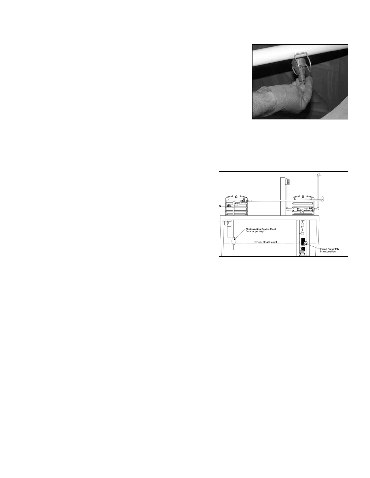
3. Remove the spray nozzle by unsnapping the stainless steel spring from
the pipe. Clean any debris and replace them. The spray nozzle piping
can be removed at the unions and cleaned with a bottle brush or water
pressure if needed.
NOTE: If efuent samples are needed, a grab sample can be taken by placing the sample bottle below the
out fall of the recirculation device, being careful not to touch the bottle to any contaminated surface. The
efuent sample should be collected and transported according to the testing facility requirements. Efu-
ent should be clear with a slight yellow tint and should be free
from odor. Efuent results should be in accordance with NSF
Standard 40 Class 1 requirements, BOD less than 25mg/L and
TSS less than 30mg/L.
Section 7.0 Recirculation Device
1. Check to see if the stainless steel rod is moving up and
down freely. Also, check to see if the ball oat is located at
the proper level. When the ball oat is at its lowest position,
it should be located equal to or just above the on position of
the timer enable oat. (gure 1)
2. Check that the design recirculation rates are maintained by observing the discharge through all ve out
falls of the recirculation assembly. Adjust as needed by loosening the quick disconnects and leveling.
TROUBLESHOOTING GUIDE
The AeroCell®& Bio-COIR® systems will handle all domestic wastewater from your home. By the term
wastewater we are referring to rapidly biodegradable material. To keep maintenance at a minimum level
and to prevent the system from malfunctioning, the following guidelines need to be followed:
* Since aerobic bacteria are responsible for treating the wastewater, inorganic or non-rapidly biodegrad-
able materials should not be put into the system. Examples of improper items are: plastic products,
rubber products, sanitary napkins or tampons, washcloths, cigarette butts, coffee grounds, eggshells,
matches, or other non-biodegradable objects.
* Do not dispose of cooking grease or large amounts of oil into system; instead pour it into a container
and dispose of it properly.
* To minimize pump-out frequency, limit use of garbage disposals.
* Lint from lint catchers, hair, etc., should be disposed in the trash and not washed down the drain.
* Water softener backwash should not be routed through the system. Another source of disposal should
be used.
* Diapers can be rinsed out in the toilet; however, do not ush cloth or disposable diapers down the toi-
let.
* Large amounts of harsh chemicals, high sudsing detergents, disinfectants or any substance that kills bac-
teria must not be discharged into the system.
Figure 1

6
* The system will not perform to its fullest capabilities if volumetric overload is allowed to occur. This
occurs whenever excessive water, above the designed ow rate, is allowed into the system. Excessive
water use or leaking plumbing xtures may cause this condition.
The AeroCell®& Bio-COIR® systems are very effective and reliable in the treatment of domestic wastewa-
ter. The problems outlined here occur only in a very small percentage of total installations. They can all
be corrected and most be prevented.
1. Alarm condition exists:
a. Check the breaker for the pump.
b . If the breaker is engaged, set HOA switch to HAND to see if the pump runs.
c. Check the nozzles to be sure they are not clogged and restricting the ow into the module.
d. Check the timer enable oat to insure that it is operating properly.
e. Check the timer override oat to insure that it is operating properly.
f. Clean the lter panels on the ltered pump vault to assure that efuent is getting into the vault.
g. Check the high water alarm oat to see if it is stuck in the up position.
2. Excessive solids in the module:
a. Check to see if the efuent lter cartridge has been removed.
b. Check the septic tank to see if it appears normal. If not, check with the PROPERTY OWNER to
determine what inappropriate materials might have been added to the waste stream.
3. Recirculation device is not splitting properly:
a. Check the out falls for clogging.
b. Check the device for level.
4. Control panel malfunction:
a. Check all fuses and breakers.
b. Check originating power source.
c. Check timer setting to assure it is set according to original design parameters.
5. Efuent quality is out of design parameters:
a. Check the septic tank to see if it needs pumping.
b. Check the dosing tank to see if it needs pumping.
c. Check the out-falls for contamination.
d. Assure that proper procedures were used in taking the sample.
e. Check water usage to insure that it is within design parameters.
f. Check the nozzles for clogging.
g. Check the timer setting to assure it is according to design parameters.
SAFETY
As raw wastewater may and usually does contain some level of unsafe microorganisms, proper respect
and care must be given to safety. When coming into contact with raw sewage, do not fear the contact, but
do take proper precautions to avoid potential danger.
Follow these simple safety precautions whenever exposed to wastewater:
* Always wash with soap and water after handling any contaminated item. The use of good bactericide

soap is strongly recommended.
* Wear disposable rubber gloves when handling wastewater-contaminated items or chlorine tablets.
* Always dispose of scum, rags, trash, debris, or soiled material in a proper waste container.
* If a wastewater spill or leak occurs in a yard, ush area with plenty of clean water and disinfect. If a spill
or leak occurs in the house, clean with a dilute solution of bleach.
* Protect any injury, wound, open cut, etc. from exposure to wastewater.
* If an illness or disease is suspected of coming from exposure to sewage, get proper medical attention
immediately.
* Report all accidents relating to sewage exposure to the proper supervisory personnel.
Follow these safety precautions when performing any excavation or construction work:
* Follow all construction safety procedures during installation.
* Follow electrical safety procedures during installation.
* Fill all holes and depressions in and around the installation area; remove and dispose of all debris from
installation.
TECHNICAL DATA/DRAWINGS INDEX
ATS-SCAT-8-AC-C500 8 PDS-ED-1.5 16
ATS-SCAT-86-AC-C750 8 PDS-GT-1.5 16
ATS-SCAT-88-AC-C100010 9 AC-FT-3 17
ATS-SCAT-886-AC-C1250 9 AC-JSB-4 17
ATS-SCAT-888-AC-C1500 10 AC-CP-S-C-T 18
ATS-SCAT-8-BC-C500 10 ATS-GRD-100/80/20 18
ATS-SCAT-86-BC-C750 11 ATS-GRD-100/80/20-N 18
ATS-SCAT-88-BC-C1000 11 RB-CTA-26x6 19
ATS-SCAT-886-BC-C1250 12 RB-R-26x18 19
ATS-SCAT-888-BC-C1500 12 RB-L-26 19
ATS-SCAT-6 13
ATS-SCAT-8 13
A300-8” Series Efuent Filter 14
FPV-H44-4 14
P-SE-13T 15
7

8
500 GPD AeroCell® System
www.quanics.net/autocad.htm
750 GPD AeroCell System
www.quanics.net/autocad.htm
The septic tank shall have a minimum L:W ratio
of equal to or greater than one.
The septic tank shall have a minimum L:W ratio
of equal to or greater than one.

9
1000 GPD AeroCell® System
www.quanics.net/autocad.htm
1250 GPD AeroCell System
www.quanics.net/autocad.htm
The septic tank shall have a minimum L:W ratio
of equal to or greater than one.
The septic tank shall have a minimum L:W ratio
of equal to or greater than one.

10
1500 GPD AeroCell® System
www.quanics.net/autocad.htm
500 GPD Bio-COIR® System
www.quanics.net/autocad.htm
The septic tank shall have a minimum L:W ratio
of equal to or greater than one.
The septic tank shall have a minimum L:W ratio
of equal to or greater than one.
500 gallons per day
85ft3of Bio-COIR media
5.88 gpd/ft3hydraulic loading rate
Four 120 degrees spray nozzles

11
750 GPD Bio-COIR® System
www.quanics.net/autocad.htm
1000 GPD Bio-COIR System
www.quanics.net/autocad.htm
The septic tank shall have a minimum L:W ratio
of equal to or greater than one.
The septic tank shall have a minimum L:W ratio
of equal to or greater than one.
750 gallons per day
138ft3of Bio-COIR media
5.88 gpd/ft3hydraulic loading rate
Eight 120 degrees spray nozzles
1000 gallons per day
170ft3of Bio-COIR media
5.88 gpd/ft3hydraulic loading rate
Eight 120 degrees spray nozzles

12
1250 GPD Bio-COIR® System
www.quanics.net/autocad.htm
1500 GPD Bio-COIR System
www.quanics.net/autocad.htm
The septic tank shall have a minimum L:W ratio
of equal to or greater than one.
The septic tank shall have a minimum L:W ratio
of equal to or greater than one.
1250 gallons per day
223ft3of Bio-COIR media
5.88 gpd/ft3hydraulic loading rate
Twelve 120 degrees spray nozzles
1500 gallons per day
255ft3of Bio-COIR media
5.88 gpd/ft3hydraulic loading rate
Twelve 120 degrees spray nozzles

13
ATS-SCAT-6 ATS-SCAT-8
ADVANCED TREATMENT
SCAT®AeroCell®&Bio-COIR®
AeroCell & Bio-COIR Specications
Model # GPD
Rating
Nozzles Modules Media
(ft3)
Loading
(gpd/ft3)
Septic Tank
(gal)
Pump Tank
(gal)
Individual
Dose Volume
(gal)
Discharge
Volume per
Individual Dose (gal)
Doses
per
24 hrs.
ATS-SCAT-8-AC-C500
ATS-SCAT-8-BC-C500
500* 4 1 85 5.88 1000 500 25.6 5.12 98
ATS-SCAT-86-AC-C750
ATS-SCAT-86-BC-C750
750* 8 2 138 5.43 1500 750 51.2 10.2 73
ATS-SCAT-88-AC-C1000
ATS-SCAT-88-BC-C1000
1000* 8 2 170 5.88 2000 1000 51.2 10.2 98
ATS-SCAT-886-AC-C1250
ATS-SCAT-886-BC-C1250
1250* 12 3 223 5.61 2500 1250 76.8 15.3 81
ATS-SCAT-888-AC-C1500
ATS-SCAT-888-BC-C1500
1500* 12 3 255 5.88 3000 1500 76.8 15.3 98
*The Zabel®
A300-8x18-VC model efuent lter is used in systems of 1200 gpd or less. The A300-8x26-VC lter is used in systems up to 1800 gpd.
The septic tank shall have a minimum L:W ratio of equal to or greater than one.
Features
• Efuent discharge and carbon lter vent assemblies included
• Fiberglass lid with neoprene gasket and security screws included
• Indented at spots on bottom for easy grommet and outlet pipe installation.
• .015 - .016 lbs/ft
3
/day organic loading rate
Warranty for Defects in Material and Workmanship
• Fiberglass SCAT Module - 2 years
• Efuent Discharge and Vent Assembly - 2 years

14
EFFLUENT FILTER
Filter Series (8”)
A300-8x18-VC
GPD: 1200 / FS: 1/32”
A300-8x26-VC
GPD: 1800 / FS: 1/32”
Features
• Patented efuent lter for light commercial, grease
traps and in conjunction with advanced treatment
systems
• Average of 50% to 90% reduction in TSS within 6
months of installation
• Average of 20% to 45% reduction in BOD5 within 6
months of installation, reduction is dependent on the
make-up of the wastewater
• Average of 60% to 90% reduction in FOG within 6
months of installation
• Filter cartridges are green for easy identication
• Outlet hub accepts 4” or 6” SCH 40 outlet pipe
• All Zabel® Filters accept SmartFilter® alarm switch
GPD = Maximum Gallons Per Day
FS = Filtration Size
Warranty for Defects in Material and Workmanship
Efuent Filters - Limited Lifetime
FILTERED PUMP VAULT
Hanging
FPV-H44-4, FPV-H56-4
High density non-corrosive polyethylene plastic with stainless steel
screws
Features
• Hanging ltered pump vault installs into primary or
pump tanks
• Protects pump and disposal eld from solids larger
than 1/16”
• Available with either 2 or 4 lter plates
• Includes maintenance plate for servicing ease
Warranty for Defects in Material and Workmanship
FPVs - 2 Year
All FPVs when used with a QUANICS pump -10 year
FPV-H44-4
FPV-H56-4
A300-8x18-VC A300-8x26-VC

15
PRESSURE DISTRIBUTION
Pumps
P-SE-13T
Specications
Capacities: From 15 - 80 GPM
Heads: To 260 FT
Motor: 1/2 HP; hermetically sealed with automatic thermal
overload
Electrical: 115V, 12.0 FLA, 1PH, 60Hz
Operation: Manual model (controls required)
Minimum Diameter: 4” (102mm)
Impeller: Delrin®, closed vane type
Solids handling: 1/8” (3.2mm)
Power Cord: 10’ (3M), 300 V SJOW jacketed, 2-wire with
ground
Materials of Construction: 300 grade stainless and cast-iron
Discharge: 1-1/2”
Warranty for Defects in Material and Workmanship
• All components - 3 Years
STEP SYSTEMS
Efuent Discharges
PDS-ED-1.5
Materials
Pipe
• 1.5” or 2” SCH 40 PVC
• 1.5” or 2” PVC ex tubing
True Union Ball Valve
• PVC Plastic
• Double block, full port design
• 1.5” or 2” slip/slip hubs
Fittings
• SCH 40 PVC threaded slip adapter
• SCH 40 PVC slip/slip adapter
Warranty for Defects in Material
and Workmanship
• All components - 2 Years
PDS-ED-2.0

16
Pressure Distribution
Grommets
PDS-GT-1.5
Materials
• 65 Durometer PVC
Warranty for Defects in Material and
Workmanship
• All components - 2 Years
PDS-GT-2.0
STEP SYSTEMS
Float Tree
AC-FT-3
Materials
Pipe
• 1.5” or 2” SCH 40 PVC
• 1.5” or 2” PVC ex tubing
True Union Ball Valve
• PVC Plastic
• Double block, full port design
• 1.5” or 2” slip/slip hubs
Fittings
• SCH 40 PVC threaded slip adapter
• SCH 40 PVC slip/slip adapter
Warranty for Defects in Material and Workmanship
• All components - 2 Years

17
AC-JSB-4
STEP SYSTEMS
Junction Box
Materials
Lid & Box
• High impact, corrosion resistant thermoplastic
• Weatherproof
• 1/2” UL approved, CSA Certied round cable
liquid-tight strain
relief connectors
• 1-1/2” terminal adapter hub
Gasket
• Flexible PVC
Screws
• Brass
Warranty for Defects in Material and Workmanship
• Junction Boxes - 3 Years
STEP SYSTEMS
Control Panel
AC-CP-S-C-T
Specications
Enclosure
• Measures 10x8x4 inches (25.40x20.32x10.16 cm).
NEMA 4X (ultraviolet stabilized thermoplastic with re-
movable anges for outdoor or indoor use).
• Magnetic Motor Contactor controls pump by switching
hot electrical lines
• HOA Switch for manual pump control (mounted on cir-
cuit board)
• Float Switch Terminal Block
• Alarm and Control Fuses
• Programmable Timer with separate variable controls al-
lows for setting the on and off times from .05 seconds to
30 hours.
• Circuit Breaker provides pump disconnect and branch
circuit protection
Power Supply
• Pump-120/208/240V, 7-15FLA
• Alarm-120V
Standard Alarm Package
• Red Alarm Beacon provides 360 visual check of alarm
condition
• Exterior Horn Test/Normal/Silence Switch allows alarm
horn to be silenced and testing of horn and light to en-
sure proper operation of alarm system
• Horn Silence Relay automatically resets alarm after
alarm condition has been resolved (mounted on circuit
board)
Warranty for Defects in Material and Workmanship
• Control Panel - 3 Years

18
ATS-GRD-100/80/20
ADVANCED TREATMENT
Recirculation Devices
Materials
Riser and Lid
• High density non-corrosive
polyethylene plastic
• Tested to withstand up to a
2500 lb wheel load
• Neoprene gasket
• Stainless steel tamper re-
sistant hardware
• 26” diameter lid
Efuent Discharge
Assembly
• 1.25” Sch 40 PVC Pipe
• Rubber Grommets
Float Valve Assembly
• 60” Stainless steel rod
• Polypropylene oat
Warranty for Defects in
Material and Workmanship
• Riser and Lid - 2 Years
• Efuent Discharge
Assembly - 2 Years
• Float Valve Assembly -
2 Years
ATS-GRD-100/80/20-N
Materials:
Risers and Lids
• High density non-corrosive polyethyl-
ene plastic
• Stainless steel screws
• Neoprene gasket
IMPORTANT:
• When adding risers together for
deeper installations QUANICS does
not recommend exceeding a maximum
depth of 48”.
• Neoprene gaskets must be installed as
per instructions
• To prevent unauthorized entry install
all tamper resistant fasteners as per
instructions
Warranty for Defects in Material and
Workmanship
• Riser, Lids & Tank Adapters - 2 Years
RB-RTA-26x2 (Retrofit Tank Adapter)
STEP SYSTEMS
Risers, Lids, Tank Adapters
RB-L-26 (Lid)
RB-R-26x18 (Riser)
RB-CTA-26x6 (Cast-in Tank Adapter)

19
Wiring Schematics
This manual suits for next models
9
Table of contents
Popular Water System manuals by other brands

Everpure
Everpure CG5-20S Replacement Cartridge DEV9108-27 Specification sheet

Triton
Triton Purificare TRI Series manual

Beko
Beko BEKOMAT 16i CO Translation of original installation and operation manual

Geekpure
Geekpure RO4 Installation and maintenance manual

ClayTech
ClayTech CMS B3A1 owner's manual

Infiltrator
Infiltrator Presby Advanced Enviro-Septic Design and installation manual

Everpure
Everpure 2K-Plus EV9612-61 Specification sheet

Everpure
Everpure Scalekleen EV9796-20 Specification sheet

Craftsman
Craftsman 390.252158 owner's manual

OMEGA AIR
OMEGA AIR MDHI installation manual

Everpure
Everpure 4CB5-MR Cartridge E17-17 Specification sheet

North Star
North Star NSCWC Installation and operation manual