Quantum KuDoz 7 series User manual

Declaration of Conformity
QUANTUMDESIGNS(HK)LTD.
20th Floor, Devon House, Taikoo Place, 979 King’s Road,
Quarry Bay, Hong Kong
declares that the product
Motherboard
KuDoz 7
is in conformity with
(reference to the specification under which conformity is declared in
accordance with 89/336 EEC-EMC Directive)
þ EN 55022 Limits and methods of measurements of radio disturbance
characteristics of information technology equipment
þ EN 50081-1 Generic emission standard Part 1:
Residential, commercial and light industry
þ EN 50082-1 Generic immunity standard Part 1:
Residential, commercial and light industry
European Representative:
QDICOMPUTER(UK)LTD. QDICOMPUTER( SCANDINAVIA)A/S
QDISYSTEMHANDELGMBH QDI EUROPEB.V
QDICOMPUTER(FRANCE)SARL QDICOMPUTERHANDELSGMBH
LEGENDQDISPAINS.L QDICOMPUTER(SWEDEN)AB
Signature : Place / Date : HONG KONG/2001
Printed Name : Xu Wenge Position/ Title : Assistant President

Declaration of Conformity
Trade Name: QDI Computer ( U. S . A. ) Inc.
Model Name: KuDoz 7
Responsible Party: QDI Computer ( U. S. A.) Inc.
Address: 41456 Christy Street
Fremont, CA 94538
Telephone: (510) 668-4933
Facsimile: (510) 668-4966
Equipment Classification: FCC Class B Subassembly
Type of Product: Motherboard
Manufacturer:Quantum Designs (HK) Inc.
Address: 20th Floor, Devon House, Taikoo Place
979 King’s Road, Quarry Bay, HONG
KONG
Supplementary Information:
This device complies with Part 15 of the FCC Rules. Operation is subject to
the following two conditions : (1) this device may not cause harmful interfer-
ence, and (2) this device must accept any interference received, including
interference that may cause undesired operation.
Tested to comply with FCC standards.
Signature : Date : 2001

II
CONTENTS
1. Introduction................................................ 1
Overview........................................................................1
KeyFeatures ..................................................................1
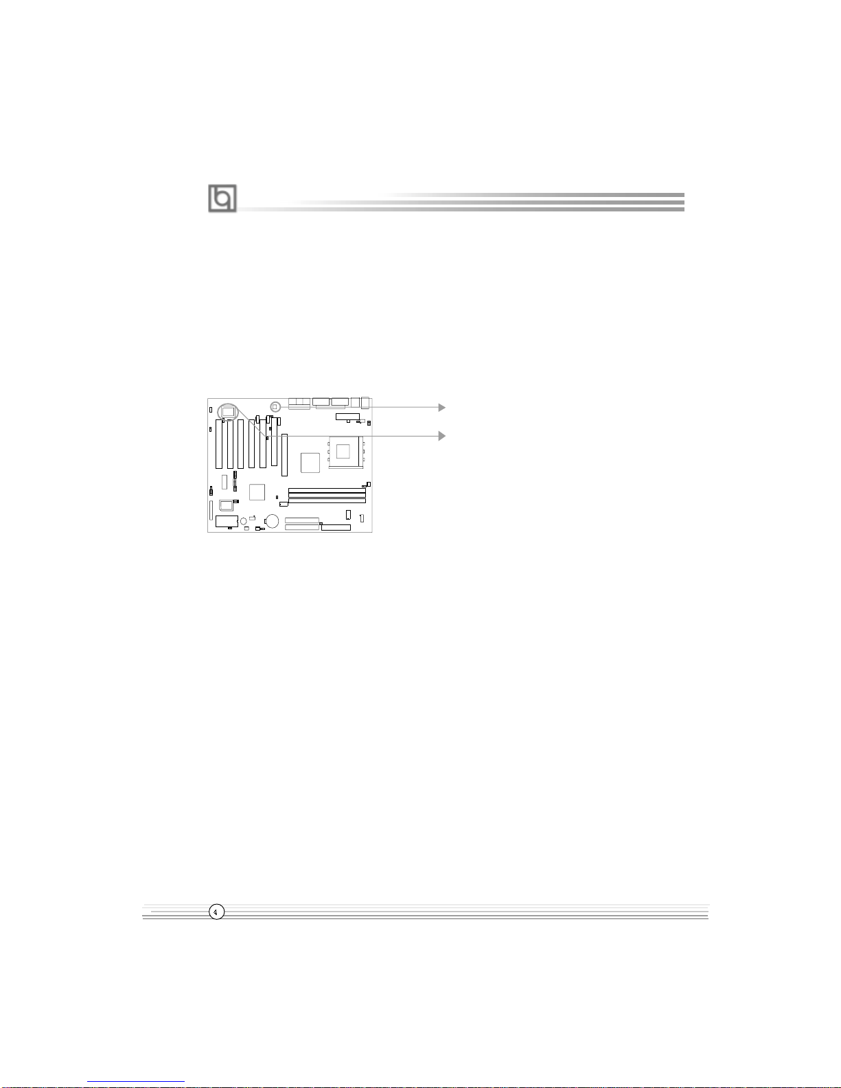
CreativeCT5880(optional)....................................................4
2. Installation Instructions............................. 5
External Connectors .............................................. 5
PS/2Keyboard&PS/2Mouse Connector.........................5
USB1,USB2Connectors .................................................5
USB3, 4, 5, 6Connectors ................................................5
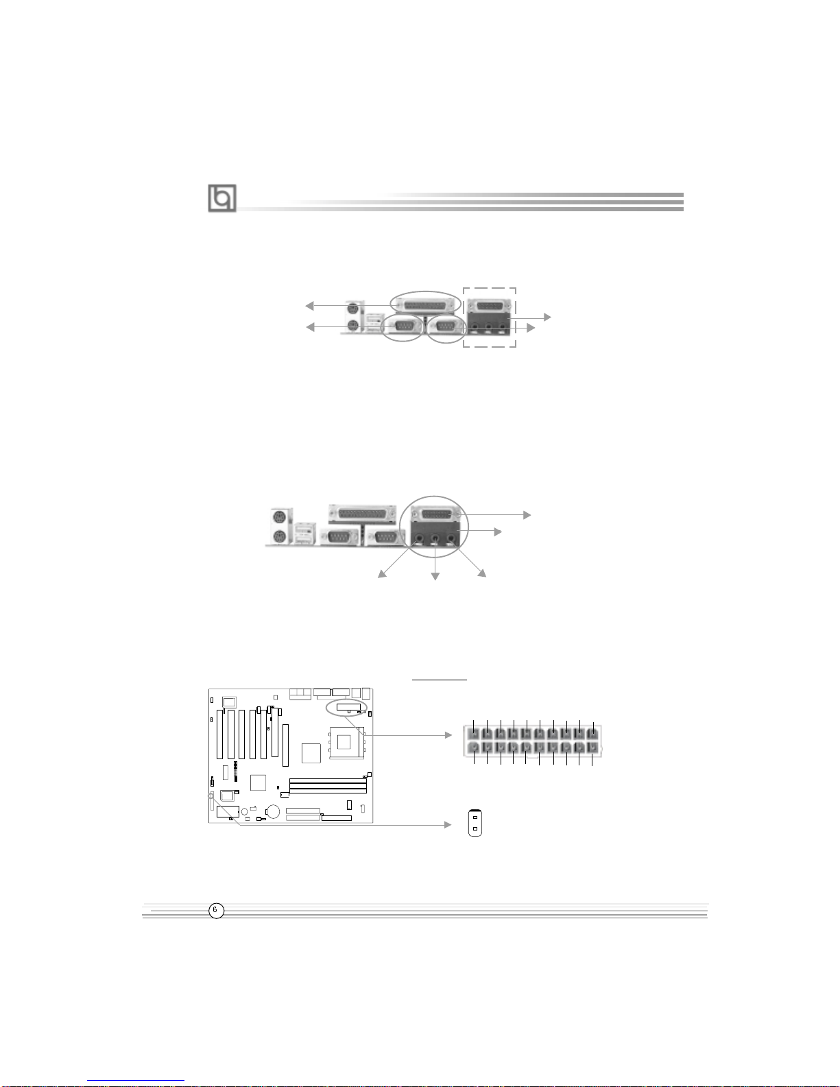
ParallelPort andSerial PortConnectors............................. 6
Line-injack,Mic-injack,Speaker-outjackandMIDI/Joystick
Connector(optional)...........................................................6
ATX Power Supply Connector & Power Switch ...............6
HardDiskLEDConnector(HD_LED)...............................7
ResetSwitch( RESET)...................................................7
SpeakerConnector(SPEAKER) .....................................7
PowerLEDConnector(PWRLED) ..................................7
ACPILEDConnector(ACPILED) .....................................7
GreenLEDConnector(GREENLED) ...............................7
HardwareGreenConnector (SLEEP SW) ......................7
FanConnectors(CPUFAN,CHSFAN,BAKFAN) ..............8
Infrared Header ( IrDA )...................................................8
Wake-UpOnLAN (WOL ) ...............................................8
Wake-UpOnInternalModem(WOM) ..............................9
InternalAudio Connectors
(AUX,CD_IN,MODEM)(optional) ..................................9
AdvancedCommunicationsRiserSlot
(ACR)................................................................................10
SmartCard ReaderConnector(SCR)................................10
JumperSettings.............................................................11
OverclockingJumper Setting(JFSB )..................................11
CPUBusRatioSelection(JFID)..........................................12
CPUCoreVoltageSelection(JVID)....................................12
CPUBus RatioSetting( J1,J3)...........................................13
CPUCore VoltageSetting(J4)...........................................14

II
CONTENTS
BIOS-ProtectEasyJumper( JAV)...................................15
Clear CMOS(JCC )........................................................15
Enable/DisableonboardAudio
(JP1,JP2,JP3 )(optional )..............................................16
Enable/DisableOnboardSoundBlaster
( J2 )( optional )..............................................................16
EnableUSBKeyDeviceWake-upFunction
(JUSB1,JUSB2,JUSB4)...............................................17
SCR/FloppyBSelection( J5,J6 )...................................17
SuspendtoRAM Switch( JSTR)...................................18
Enablekeyboard Wake-upFunction( JKB)....................18
3. BIOS Description..................................19
UtilitySupport............................................................19
AWDFLASH.EXE............................................................19
AWARD BIOSDescription.......................................20
EnteringSetup................................................................20
LoadFail-Safe Defaults..................................................20
LoadOptimizedDefaults................................................20
StandardCMOSFeaturesSetup....................................20
Frequency/VoltageControlSetup..................................24
AdvancedBIOSFeaturesSetup....................................25
AdvancedChipsetFeatures Setup................................28
PowerManagementSetup.............................................31
PnP/PCIConfigurationsSetup.........................................34
IntegratedPeripherals....................................................35
PCHealthStatus............................................................38
Supervisor/UserPassword...........................................39
Appendix
QDIDriver CD2000..................................................A.1
ManageEasy.............................................................A.2
BIOS-ProtectEasy......................................................A.2
NortonAntiVirus........................................................A.2
LogoEasy...................................................................A.3
RecoveryEasy............................................................A.4
BootEasy....................................................................A.12
KuDoz7(Francais)................................................A.16
StepEasy....................................................................A.19
Layout

Manual for KuDoz 7 series
Chapter 1
Introduction
Chapter 1
Chapter 1
Introduction
Overview
TheKuDoz 7seriesarehighperformance,cost-effectiveandenergy efficientmotherboards
from200MHzand 266MHz FSBbasedon Socket-A processors.Theyutilize the ApolloKT
266chipsetconsisting ofVIA VT8366and VT8233.Theysupport theUltraDMA-33/66/100,
DDR SDRAM and AGP 4x. They also provide one ACR slot and one SCR(Smart Card
Reader) interface connector. In addition, advanced features are supported such aswake-
uponLAN,wake-uponinternal/externalmodem,wake-upbyhotkeysofPS/2keyboard,ACPI
powermanagementand hardwaremonitoring.
IMPORTANT: OnboardAudio( AC97codec) andOnboardSoundBlaster(Creative®CT5880
) are optional. Please take note of the difference.
Key Features
Form Factor
l ATX form factor of 305mm x235mm
Microprocessor
lSupports200MHz/266MHz FSB
lSupportsAMDSocket-A Athlon “B”type( FSB is200MHz)/ “C”type(FSB is 266MHz)
processorsat700MHz/750MHz/800MHz/850MHz/900MHz/950MHz/1GHz/1.1GHz/
1.2GHz/1.33GHz /1.4GHz and future processors
lSupportsAMDSocket-ADuronprocessorsat600MHz/650MHz/700MHz/750MHz/
800MHz/850MHz/900MHz/950MHzandfuture processors
Chipset
l VIA Apollo KT266 chipset: VT8366( North Bridge ), VT8233( South Bridge )
l AdoptsITE IT8705FI/Ochip
Memory
l Provides three 2.5V SSTL-2, 184-pin, 64-bit data width DRAM interfaces
l SupportsPC1600/PC2100DDRSDRAM
l Supports ACPI S3 mode

Manual for KuDoz 7 series
Introduction
Onboard IDE
l Supports two PCI PIO and Bus Master IDE ports
l Two fast IDE interfaces supporting up to four IDE devices including IDE hard disks
and CDROM drives
lSupportsUltraDMA-33/66/100
OnchipI/O
l One floppy port supporting up to two 3.5” or 5.25” floppy drives with 360K/720K/
1.2M/1.44M/2.88Mformat
lTwohighspeed16550fastcompatibleUARTs(COM1/COM2/COM3/COM4selective)
with 16-byte transmit/receiver FIFOs
lOneenabledparallelportattheI/O address378H/278H/3BCH withadditional bi-
directionI/OcapabilityandmultimodeasSPP/EPP/ECP
l Provides Six USB ports and One IrDA connector
lProvides One SCR interface connector and One ACR slot
lSupportsPS/2 mouseandPS/2keyboard
l Supports LS-120 floppy disk drive and Zip drive
lAllI/Oports can beenabled/disabledin the BIOSsetup
AGPSlot
l Provides one AGP slot
l AGP v2.0 compliant
l Supports AGP 4x mode
Onboard Audio( Available on KuDoz 7-A )
lStandardAC97Codec interface
Creative® CT5880 PCI Hardware Sound ( Available on KuDoz 7-C )
l3D audio effects
l32-voice XG wavetable synthesizer
lDirect Sound/Music Hardware Accelerator
lFull-Duplexstereo
lSupports four speakers output based on Speaker-out jack and Line-in jack
Advanced Features
lProvides Trend ChipAwayVirus® On Guard
lSupports wake-up on LAN
lSupportswake-uponinternal/externalmodem
lSupports wake-up on hot keys
lSupportssystemmonitoring(monitorssystemtemperature,CPUtemperature,voltages
and fan speed)

Manual for KuDoz 7 series
Chapter 1
lSupportsQDI innovations:StepEasy,BootEasy,LogoEasy,RecoveryEasy,
BIOS-ProtectEasyandManageEasy
lProtects the system BIOS from being attacked by severe virus such as CIH, by
enabling“FlashWrite Protect”in CMOS setuporclosing the Jumper“JAV”
BIOS
lLicensed advanced AWARD( Phoenix) BIOS
lSupports Flash ROM with 2M-bit memory size, plug and play ready
lSupportsIDECDROMorSCSIbootup
Green Function
lSupports ACPI ( Advanced Configuration and Power Interface ) and ODPM ( OS
DirectedPower Management)
lSupports ACPI status: S0( full-on ), S1( power on suspend ), S3( STR ), S4( STD )
( Windows Me, Windows 2000 ), S5( soft-off )
Main Expansion Slots and Connectors
Slot/Port(Quantity) Description
PCI(5) PCIslots
IDE(2) IDEports
FLOPPY(1) Floppy drive port
DDR(3) DDR DIMMslots
USB( 6 ) USB connectors
ACR( 1 ) ACRslot
AGP( 1 ) AGPslot
SCR(1) SCRconnector
IrDA( 1 ) IrDA connector

Manual for KuDoz 7 series
Creative CT5880 chip ( Available on KuDoz 7-C )
The CT5880 provides high-quality audio performance and low CPU utilization for you.
Featuring 128-voice wave-table synthesis with very high sample rate converters. In
addition, CT5880 supports localized three-dimensional sound immersion in headphone
andfour-speakerenvironments. The four-speakerbasedon speaker-out andline-injack.
the CT5880 also supports multiple algorithm levels of reverb and chorus effects on the
wave-table sounds as well as spatial sound enhancement on MIDI and wave sounds in
two speakers. Full duplex operation also allows simultaneous audio recording and play-
back.
The motherboard has two solutions for onboard audio.
SoftSound(AC97)
(Available onKuDoz 7-A )
HardwareSound( CT 5880 )
( Available on KuDoz 7-C )
Introduction

Manual for KuDoz 7 series
Chapter 2
Installation Instructions
Chapter 2
Installation Instructions
This section covers External Connectors and Jumper Settings. Refer to the motherboard
layout chart for the locations of all jumpers, external connectors, slots and I/O ports.
Furthermore, this section lists all necessary connector pin assignments for your reference.
The particular states of the jumpers, connectors and ports are illustrated in the following
figures. Before setting the jumpers or inserting these connectors, please pay attention to
thedirections.
Be sure to unplug the AC power supply before adding or removing expansion
cards or other system peripherals, otherwise your motherboard and expansion
cards might be seriously damaged.
External Connectors
PS/2 Keyboard Connector, PS/2 Mouse Connector
PS/2 keyboard connector is for the usage of PS/2 keyboard. If using a standard AT size
keyboard, an adapter should be used to fit this connector. PS/2 mouse connector is for the
usageofPS/2 mouse.
USB1, USB2 Connectors
Two USB ports are for connecting USB devices.
USB3, USB4 and USB5, USB6 Connectors
Four USB ports are not available on the back panel. Therefore, we provide a 10-pin cable(
optional) toconnect onboard USBheadersand USB devices.
Chapter 2
PS/2 Mouse Connector
PS/2 Keyboard Connector Optional
USB1
USB2 Optional
1
+5v
DT3-
DT3+
GND
GND
GND
GND
DT4+
DT4-
+5v
1
+5v
DT5-
DT5+
GND
GND
GND
GND
DT6+
DT6-
+5v
USB6, USB5
USB4, USB3

Manual for KuDoz 7 series
Parallel Port, Serial Port Connectors ( UART1, UART2 )
Theparallel portconnectorcanbeconnectedtoaparalleldevicesuchasaprinter.Theserial
ports UART1,2 connectors can be connected to serial port devices such as serial port
mouses.Youcan enable/disablethem andchoose theIRQor I/Oaddress in“INTEGRATED
PERIPHERALS”fromAWARD BIOS SETUP.
Line-in jack, Microphone-in jack, Speaker-out jack and MIDI/Joy-
stick Connector( Available on KuDoz 7-A/-C )
The Line-in jack can be connected to devices such as a cassette or minidisc player for
playbackorrecording.TheMicrophone-injackcanbeconnected toa microphonefor voice
input. The Speaker-out jack allows you to connect to speakers or headphones for audio
outputfromtheinternalamplifier.
The MIDI/Joystick connector allows you to connect a game joystick or a MIDI device.
Note: For the KuDoz 7-C motherboard, the rear out jack replaces Line-in jack to
connect powered speakers for audio output.
Installation Instruction
ATX Power Supply Connector & Power Switch ( POWER SW )
Be sure to connect the power supply plug to this connector in its proper orientation. The
power switch ( POWER SW ) should be connected to a momentary switch (power button).
When powering up your system, first turn on the mechanical switch of the power supply (
if one is provided ), then push once the power button. When powering off the system, you
needn’t turn off the mechanical switch, just
Push once
*the power button.
Note: * If you change “soft-off by PWRBTN”from default “Instant-off”to “Delay 4
Sec”in the “POWER MANAGEMENT SETUP”section of the BIOS, the power button
should be pressed for more than 4 seconds before the system powers down.
Parallel Port
UART1 UART2
Optional
POWER SW
ATX Power Supply Connector
20
1
5V5V-5VGNDGNDPSON-12V
3.3V GND
12V5VSB
5V
GND
3.3V GND5V GNDPWOK3.3V
GND
MIDI/Joystick
Speaker out Line in Microphonein
Optional

Manual for KuDoz 7 series
Chapter 2
Hard Disk LED Connector ( HD_LED )
Theconnectorconnects tothecase’s IDEindicatorLED indicatingtheactivity statusofIDE
hard disk. The connector has an orientation. If one way doesn’t work, try the other way.
Reset Switch ( RESET )
The connector connects to the case’s reset switch. Press the switch once, the system
resets.
Speaker Connector ( SPEAKER )
The connector can be connected to the speaker on the case.
Power LED Connector ( PWR LED )
When the system is in S0( full-on ) status, the LED is on. When the system is in S1( power
on suspend ) status, the LED is blink. When the system is in S3( STR ) or S5( soft-off )
status, the LED is off. The connector has an orientation.
ACPI LED Connector ( ACPI LED )
TheACPILEDis adouble-colorlightwiththreepins.Pin1andPin2drivedifferentcolorlights.
If Pin1 drives the orange light , then, Pin2 drives the green light, the following status will
come out. When the system is in S0 status, the LED is green. When the system is in S1
status,the LEDisgreenblink.When thesystemisinS3 status,theLEDisorange.Whenthe
system is inS5 status, the LED is off.
GREEN LED Connector ( GREEN LED )
Whenthesystem is inS0,S1 or S5status,the LED isoff. When thesystemis in S3orAPM
power on suspend status, the LED is on.
Hardware Green Connector ( SLEEP SW )
Push once the switch connected to this header, the system enters suspend mode.
POWER
SW SLEEP
SW
SPEAKER RESET GREEN LED
PWRLED
ACPILED
HD_LED
SPEAKER RESET GREEN LED
ACPILED SLEEP
SW PWRLED
HDD LED(+) HDD LED(-)
ORANGE(-)
GREEN(-)
LED+
POWER
GND
EMPTY
EMPTY
SLEEP
GND
LED+
LED-
LED-
LED-
LED-
LED+
EMPTY
GND
RESET
SPKDATA
NC
GND
VCC
POWER
SW

Manual for KuDoz 7 series
Installation Instruction
Fan Connectors ( CPUFAN, CHSFAN, BAKFAN )
ThefanspeedsofCPUFANandCHSFANcanbedetectedandviewedin“PCHealth”section
of the BIOS. They will be automatically turned off after the system enters suspend mode.
Infrared Header ( IrDA )
This connector supports Infrared transmitting and receiving. If using this function, set
“UART Mode Select” to IrDA or ASKIR and configure the settings in the “INTEGRATED
PERIPHERALS”section of theBIOS.
Wake-Up On LAN ( WOL )
Through the Wake-Up On LAN function, a wake event occurring from the network can
wakeupthe system. Ifthis function isto be used,pleasebe sureanATX 2.01powersupply
of which 5VSB line is capable of delivering 720mA, and a LAN adapter which supports this
function is used. Then connect this header to the relevant connector on the LAN adapter,
set“Wakeupon LAN/Ring”asEnabledinthe“POWERMANAGEMENT SETUP”sectionof
theBIOS.Save&exit,thenboottheoperatingsystemonce tomake surethis functiontakes
effect.
VCC
IRRX
GNDIRTX
NC
VCC
1
1+5VSB
GND
Signalforwaking up
GND
NC
+12V
BAKFAN
GND
SENSOR
+12V
CHSFAN
1
1
GND
SENSOR
+12V
CPUFAN
1

Manual for KuDoz 7 series
Chapter 2
Wake-Up On Internal Modem ( WOM )
Through the Wake-Up On Internal Modem function, the system which is in the suspend or
soft-off status can be waked up by a ring signal received from internal modem. If this
function is to be used, be sure an internal modem card which supports the function is used.
Then connect this header to the relevant connector on the modem card, set “Wake up on
LAN/Ring” asEnabledinthe“POWERMANAGEMENTSETUP”sectionoftheBIOS.Save&
exit, then boot the operating system once to make sure this function takes effect.
Internal Audio Connectors ( AUX, CD_IN, MODEM )
( Available on KuDoz 7-A/-C )
AUX and CD_IN connectors allow you to receive audio input from such sound sources as
a CDROM, TV tuner, or MPEG card. The MODEM connector allows the onboard audio to
interface with avoicemodem cardwith asimilar connector.It allows connecting the mono_in
(such as a phone) or mono_out (such as a speaker) between the onboard audio and the
voicemodemcard.
Common
Mono-Out (to Modem)
GND
MODEM
CD_IN
1Phone-In (from Modem)
Right Channel
AUX
GND
1Left Channel
Right Channel
1Left Channel
1+5VSB
GND
Signalforwaking up

Manual for KuDoz 7 series
Installation Instruction
Advanced Communications Riser Slot ( ACR )
TheACR connectorusesastandardconnectorthatisreversedandoffset.LegacyAMRcard
can be plugged into the ACR slot and works without modification. ACR provides a common
architectureforanalogmodem,Ethernet,phonelinenetworking andso on.It supportslegacy
AMRriserdesigns for modemandaudio codecs.
Note:
For the KuDoz 7, the AMR card should be set as AMR Primary card to use only.
For the KuDoz 7-A, to avoid conflict, you should set the AMR card as Slave when
use onboard audio codec( AC97 Codec ) or set the AMR card as Primary and
jumpers JP1, JP2, JP3 as disabling onboard audio codec( AC97 Codec ) when use
the audio codec on the AMR card.
For the KuDoz 7-C, the PCI1 slot can only use Slave card, and the AMR card should
be set as AMR Primary card to use only.
Smart Card Reader Connector( SCR )
The SCRinterfaceconnector istheinterface betweenthe motherboardandthe SmartCard.
The SCR is built in IT8705F I/O chip and includes a standard UART to control Smart Card
interface handshaking and then performs data transfers. The SCR can be used for a broad
rangeofapplications inGSM,ID, payTV,bankingand soforth.It also providesa Smart Card
clock divider for those ICC ( Integrated Circuit Card ) without internal clocks. If use this
function,set“UARTModeSelect”toSCRinthe“INTEGRATEDPERIPHERALS”sectionofthe
BIOSandjumpersJ5,J6asSCRenabled.
SCRFET#
VCC 1
NC
SCRCLK
RFU1
GND
NC
LED
NC
SCRREST
RFU2
SCRIO
SCRPRES#
NC
SCR1
ACR Slot

Manual for KuDoz 7 series
Jumper Settings
Jumpersarelocated onthe motherboard,theyrepresent, clearCMOS jumperJCC,enable
BIOSProtectEasyfunction jumper JAV etc.Pin1 of alljumpersare locatedonthe side with
a thick white line ( Pin1→), refer to the motherboard’s silkscreen. Jumpers with
three pins will be shown as to represent pin1 & pin2 connected and to
represent pin2 & pin3 connected.
Overclocking Jumper Setting ( JFSB )
ThejumperJFSBlocatedonthemainboardprovidesuserswithCPUoverclockingfeature.The
host bus speed can be set as 100/133MHz. The table below for your reference.
AMD Athlon CPU FSB is 100MHz/133MHz, but delivering twice the throughput of 100MHz/
133MHzPentiumIII-basedsystems( Ultra-Fast200MHz/266MHz). However,whetherornot
your system can be overclocked depends on your processor’s capability. We do not guaran-
tee the overclocking system to be stable.
Warning: Be sure your selection is right. CPU over speed will be dangerous! We
will not be responsible for any damages caused.
Chapter 2
JFSB
HCLK
JFSB
100MHz
133MHz
Close(default)
Open

Manual for KuDoz 7 series
CPU Bus Ratio Selection ( JFID )
Thejumper JFIDlocated onthe motherboardprovidesuserswithCPUbusratioselection.If
it is set as closed, the system detects the CPU bus ratio automatically. If it is set as opened,
the CPU bus ratio can be set manually by jumpers J1 and J3.
Installation Instruction
RATIOSETJFID
AUTOSET
JUMPERSET
Close(default)
Open
JFID
CPU Core Voltage Selection ( JVID )
The jumper JVID located on the motherboard provides users with CPU core voltage selec-
tion. If it is set as AUTO SET, the system detects the CPU core voltage automatically. If it is
setas JUMPERSET, theCPU corevoltage canbe setmanually byjumperJ4.
JVID
AUTOSET
JUMPERSET
Close
JVID
Open(default)
Vcore SET

Manual for KuDoz 7 series
CPU Bus Ratio Setting ( J1, J3 )
TheHostBusspeed bytheCPUbus ratioequalstheCPU’sinternalfrequency(CPUspeed)
IfHost Busspeed = 100MHz,CPU bus ratio=4
thenCPU speed=100MHzx4=400MHz
please set CPU bus ratio according to the following table.
Note: The most of Socket-A processors have bus ratio locked. In this case, it’s
not necessary to set the bus ratio by jumper setting. So only unlocked Socket- A
processors can adjust specified bus ratio through hardware jumper setting.
Warning: Be sure your selection is right. CPU over speed will be dangerous! We
will not be responsible for any damages caused.
J3
J1
2
1357
46
8
7531
8642
RATIO Pin(1-2) J3Jumper Pin(3-4) Pin(5-6) Pin(7-8) J1
Pin(1-2) Pin(3-4) Pin(5-6) Pin(7-8)
5 Close Close Open Close Close Close Open Close
5.5 Open Close Open Close Open Close Open Close
6 Close Open Open Close Close Open Open Close
6.5 Open Open Open Close Open Open Open Close
7 Close Close Close Open Close Close Close Open
7.5 Open Close Close Open Open Close Close Open
8 Close Open Close Open Close Open Close Open
8.5 Open Open Close Open Open Open Close Open
9 Close Close Open Open Close Close Open Open
9.5 Open Close Open Open Open Close Open Open
10 Close Open Open Open Close Open Open Open
10.5 Open Open Open Open Open Open Open Open
11 Close Close Close Close Close Close Close Close
11.5 Open Close Close Close Open Close Close Close
12 Close Open Close Close Close Open Close Close
12.5 Open Open Close Close Open Open Close Close
Chapter 2

Manual for KuDoz 7 series
CPU Core Voltage Setting ( J4 )
ThejumperJ4 allows youtoadjust the CPUcorevoltage manually.
Voltage Pin(1-2) J4
Jumper Pin(3-4) Pin(5-6) Pin(7-8) Pin(9-10)
1.65V Close Close Close Open Close
1.675V Open Open Open Close Close
1.7V Close Open Open Close Close
1.725V Open Close Open Close Close
1.75V Close Close Open Close Close
1.775V Open Open Close Close Close
1.8V Close Open Close Close Close
1.825V Open Close Close Close Close
1.85V Close Close Close Close Close
Warning: To set CPU core voltage higher than its default core voltage is not
suggested. If you do, we will not be responsible for any damages caused.
Installation Instruction
J4
21
3
5
7
4
6
8
910

Manual for KuDoz 7 series
BIOS-ProtectEasy Jumper ( JAV )
The BIOS of the motherboard is contained inside the Flash ROM. If the jumper JAV is set
asclosed,you willbe unabletoflash theBIOSto themotherboard. Howeverinthis status,
the system BIOS is protected from being attacked by serious virus such as CIH virus.
Under specialconditions, thejumper“JAV”should beset asOPEN. For furtherdetails, refer
to the “BootEasy” part of appendix.
Settingthe jumperJAVasopen(default),meanwhiledisablingthe“FlashWriteProtect”item
from “Advanced BIOS Features ” in AWARD BIOS CMOS Setup, allows you to flash the
BIOStotheFlashROM.
TheDMI(Desktop ManagementInterface)systeminformationsuchastheCPUtype/speed,
memory size, and expansion cards will be detected by the onboard BIOS and stored in the
flashROM.Whenever thesystemhardware configuration ischanged, DMI informationwill
beupdated automatically.However, settingjumperJAVasclosedmakesflashing BIOSand
updating DMI information impossible. Therefore, set JAV as open when changing the sys-
temhardwareconfiguration, or theerrormessage “Unknown FlashType”willbe displayed
on the screen, and DMI information update will be fail.
Clear CMOS ( JCC )
Ifyou wanttoclearCMOS,unplug theAC powersupply first,closeJCC(pin1&pin2 )once,
set JCC back to the normal status with pin2 & pin3 connected, then power on the system.
JAV
JAV
Flash Write Disabled
Flash Write Enabled
( default )
Normal status
( default )
ClearCMOS
1JCC
JCC
( Unplug the AC power supply )
1
2 3
23
Chapter 2

Manual for KuDoz 7 series
Enable/Disable Onboard Audio( JP1, JP2, JP3 )
( Available on KuDoz 7-A )
If you want to use the onboard audio( AC97 Codec ), set JP1, JP2, JP3 as closed.
Otherwise, set JP1, JP2, JP3 as opened to disable onboard audio. To avoid conflict, it is
recommended to set the jumpers as disabling onboard audio when using expansion
sound card.
Enableonboardcodec
( default )
Disableonboard codec
JP1 JP2 JP3
Close Close Close
Open Open Open
Enable/Disable Onboard SoundBlaster( J2 )
( Available on KuDoz 7-C )
If you want to use the onboard SoundBlaster(Creative® CT5880 PCI Hardware Sound ) ,
set J2 as pin1&pin2 closed. Otherwise, set J2 as pin2&pin3 closed to disable this func-
tion. To avoid conflict, it is recommended to set the jumper as disabling onboard Sound-
Blaster when using expansion sound card.
JP1
JP3
JP2
Enableonboard
SoundBlaster
( default )
Disableonboard
SoundBlaster
1
2
3
1
2
3
J2
J2
Installation Instruction
Table of contents
Other Quantum Motherboard manuals