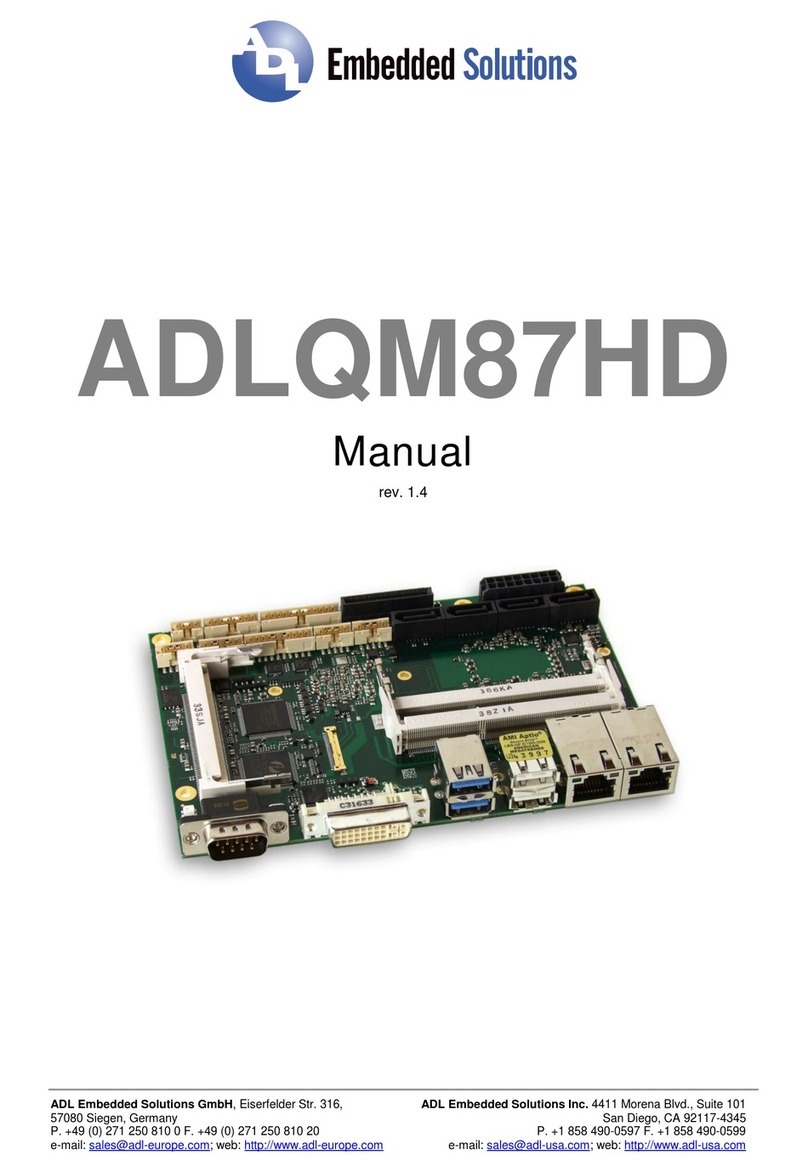
ADL Embedded Solutions ADLQM67PC User manual


Contents
ADL EmbeddedSolutions ADLQM67PC page3
Contents
0Document History.................................................................................................................................5
1Introduction...........................................................................................................................................6
1.1 Important Notes.............................................................................................................................6
1.2 TechnicalSupport.........................................................................................................................6
1.3 Warranty........................................................................................................................................6
1.4 ReturnAuthorization......................................................................................................................6
1.5 Description ofSafetySymbols......................................................................................................7
1.6 RoHS.............................................................................................................................................7
2Overview...............................................................................................................................................8
2.1 Features........................................................................................................................................8
2.2 SpecificationsandDocuments....................................................................................................10
3Connectors .........................................................................................................................................12
3.1 ConnectorMap............................................................................................................................13
3.2 PowerSupply..............................................................................................................................14
3.3 System/SM-Bus...........................................................................................................................15
3.4 Memory.......................................................................................................................................16
3.5 PCI/104-Express Bus..................................................................................................................19
3.6 DVI/HDMI....................................................................................................................................21
3.7 DisplayPort..................................................................................................................................22
3.8 VGA.............................................................................................................................................23
3.9 LCD.............................................................................................................................................24
3.10 USB.............................................................................................................................................26
3.11 LAN..............................................................................................................................................27
3.12 Audio...........................................................................................................................................28
3.13 SATAInterfaces..........................................................................................................................29
3.14 COM1 and COM2........................................................................................................................30
3.15 GPIO............................................................................................................................................31
3.16 Monitoring Functions...................................................................................................................32
4StatusLEDs........................................................................................................................................33
4.1 HD LED.......................................................................................................................................33
4.2 RGBLED.....................................................................................................................................34
5BIOSSettings.....................................................................................................................................35
5.1 Remarks forSetup Use...............................................................................................................35
5.2 Main.............................................................................................................................................36
5.3 Advanced ....................................................................................................................................38
5.3.1 PCI SubsystemSettings......................................................................................................39
5.3.2 ACPI Settings......................................................................................................................41
5.3.3 CPU Configuration ..............................................................................................................42
5.3.4 SATAConfiguration.............................................................................................................44
5.3.5 PowerControllerOptions....................................................................................................45
5.3.6 USBConfiguration...............................................................................................................46
5.3.7 SuperIOConfiguration........................................................................................................47
5.3.8 H/WMonitor........................................................................................................................49
5.3.9 SerialPort Console Redirection..........................................................................................51
5.3.10 CPUPPM Configuration......................................................................................................53
5.4 Chipset........................................................................................................................................54

Contents
page4ADL EmbeddedSolutions ADLQM67PC
5.4.1 PCH-IOConfiguration .........................................................................................................55
5.4.2 SystemAgent (SA)Configuration.......................................................................................62
5.5 Boot.............................................................................................................................................66
5.5.1 CSMParameters.................................................................................................................68
5.6 Security.......................................................................................................................................69
5.6.1 SecureBoot Policy..............................................................................................................70
5.6.2 KeyManagement................................................................................................................71
5.7 Save&Exit..................................................................................................................................73
5.8 BIOSupdate................................................................................................................................74
6MechanicalDrawing...........................................................................................................................75
6.1 PCB: Mounting Holes..................................................................................................................75
6.2 PCB: Pin1 Dimensions...............................................................................................................76
6.3 PCB: Heat Sink/DieCenter.........................................................................................................77
6.4 Heat Spreader:ChassisMount...................................................................................................78
7TechnicalData....................................................................................................................................79
7.1 ElectricalData.............................................................................................................................79
7.2 EnvironmentalConditions...........................................................................................................79
7.3 ThermalSpecifications................................................................................................................80
IAnhang:Post-Codes..........................................................................................................................81
II Annex: Resources..............................................................................................................................82
IORange.................................................................................................................................................82
MemoryRange .......................................................................................................................................82
Interrupt...................................................................................................................................................82
PCI Devices............................................................................................................................................83
SMBDevices..........................................................................................................................................83

Important Notes Chapter: Document History
ADL EmbeddedSolutions ADLQM67PC page5
0Document History
Version Changes
0.1first pre-release
0.2corrected RAM frequency;explained DPpin11, minorchanges
1.0first complete version
NOTE
Allcompanynames, brand names, and product namesreferred to in thismanualare registered or
unregistered trademarks oftheirrespectiveholders and are, assuch, protected bynationaland
internationallaw.

Chapter: IntroductionImportant Notes
page6ADL EmbeddedSolutions ADLQM67PC
1Introduction
1.1ImportantNotes
Please read thismanualcarefullybeforeyou begininstallation ofthishardwaredevice.To avoid
ElectrostaticDischarge (ESD)ortransient voltage damage to the board, adhere tothe followingrulesat
alltimes:
oYou must dischargeyourbodyfromelectricitybefore touching thisboard.
oToolsyou use must be discharged fromelectricityaswell.
oPlease ensure that neitherthe boardyouwant toinstall, northe uniton which youwant to installthis
board, isenergized before installation iscompleted.
oPlease do not touch anydevicesorcomponentson theboard.
CAUTION
Assoon asthe board isconnected to aworking powersupply,touchingtheboardmayresult in electrical
shock, even ifthe board hasnot been switched on yet.Please alsonotethat themounting holesforheat
sinksare connected to ground, so when using an externallyACpowered device, a substantialground
plane differentialcan occurifthe externaldevice'sACpowersupplyorcable doesnot include an earth
ground. Thiscould also resultinelectricalshockwhen touching the deviceandtheheatsink
simultaneously.
1.2TechnicalSupport
Technicalsupport forthisproduct can be obtained in the following ways:
oBycontacting oursupport staff at +1 858-490-0597 or+49(0)271 250 810 0
oBycontacting ourstaff viae-mail at support@adl-usa.com or support@adl-europe.com
oViaourwebsite at www.adl-usa.com/support or www.adl-europe.com/support
1.3Warranty
Thisproduct iswarranted to be free ofdefectsin workmanship and material.ADLEmbedded Solutions'
sole obligation underthiswarrantyistoprovide replacement partsorrepairservicesat no charge, except
shippingcost. Such defectswhichappearwithin12 monthsoforiginalshipment ofADL Embedded
Solutionswillbe covered,provided awrittenclaimforserviceunderwarrantyisreceived byADL
Embedded Solutionsno lessthen 30 dayspriorto theend ofthe warrantyperiod ofwithin 30 daysof
discoveryofthe defect – whichevercomesfirst. Warrantycoverage iscontingent uponproperhandling
and operation oftheproduct. Improperuse such asunauthorized modificationsorrepair,operation
outside ofspecifiedratings,orphysicaldamage mayvoidanyservice claimsunderwarranty.
1.4ReturnAuthorization
Allequipment returned to ADL EmbeddedSolutionsforevaluation, repair, credit return, modification, or
anyotherreasonmust be accompaniedbya ReturnMaterialAuthorization (RMA)number. ADL
Embedded Solutionsrequiresa completed RMArequest formto be submitted in orderto issue anRMA
number. The formcan be foundunderthe Support section at ourwebsite: www.adl-usa.com or
www.adl-europe.com. Submit the completed formto support@adl-usa.com orfaxto +1 858-490-0599 for
the USAoffice, orto rma@adl-europe.com orfaxto +49 (0)271 250 810 20 torequest anRMAfromthe
Europeanoffice in Germany.Following a review oftheinformation provided,ADLEmbedded Solutions
willissuean RMAnumber.

Description ofSafetySymbols Chapter: Introduction
ADL EmbeddedSolutions ADLQM67PC page7
1.5Description ofSafetySymbols
The following safetysymbolsare used in thisdocumentation. Theyareintended to alertthe readerto the
associatedsafetyinstructions.
ACUTERISK OFINJURY!
If you do not adhereto the safetyadvisenext to thissymbol, thereisimmediate dangerto life and health
ofindividuals!
RISK OFINJURY!
If you do not adhereto the safetyadvisenext to thissymbol, thereisdangerto life and healthof
individuals!
HAZARD TO INDIVIDUALS,ENVIRONMENT,DEVICES,OR DATA!
If you do not adhereto the safetyadvisenext to thissymbol, thereisobvioushazard to individuals,to
environment, tomaterials,orto data.
NOTEOR POINTER
Thissymbolindicatesinformation that contributesto betterunderstanding.
1.6RoHS
The PCBand allcomponentsare RoHScompliant (RoHS=RestrictionofHazardousSubstances
Directive). The soldering process islead free.

Chapter: OverviewFeatures
page8ADL EmbeddedSolutions ADLQM67PC
2Overview
2.1Features
The ADLQM67PC isahighlycomplexcomputermotherboardin the PC/104™formfactor, complyingwith
the state-of-the-art "PCIe/104™"standard. It'sbased on Intel®CPUsofthe 2nd Generation Core™ and
Celeron®families(BGA, embedded)combined with the QM67PCH. Modern DDR3 technologyprovides
top-notchmemoryperformance, accomodating up to 4 GByte ofRAM (DDR3-1066/1333/1600)via
SO-DIMM204. PCI-Express isavailablethrough the PCI/104-Express Type 1 connector, offering one x16
connection and fourx1lanesforconnecting all kindsofexpansion cardsin a PCIe/104™ stack-down
fashion. Forconnecting graphics devices, severalinterfacesare available: CRT, LVDS, HDMI,
DisplayPort. Additionalinterfacesinclude two serialports, two GigabitEthernet interfaces(LAN), two
SATAchannels(up to 6Gb/s), an audiointerface (HDA7.1), and ten USBchannels. There are also16
discrete programmable GPIOsignalsavailable.
ddd
PCIe/104 connector (type 1)
Intel®QM67PCH
SMSC®
SCH3114
LPC
Intel®
82574L
SO-DIMM204
DDR3-1066/1333
(dualchannel)
MEMORY
PowerVCCCore; VTT;
DDRVTT,GFXVCC
1,05V; 1,5V;1,8V;3,3V
BIOS
MS
2xSATA
RealTek®
ALC889 MIC1/2
7.1Audio
AUXl/r
HDALink
KB
LAN2
USB9-10
COM1-2
CRT
Intel®:
Core™ i7-2715QE,
Core™ i7-2655LE,
Celeron®827E
FDI
1.5/3/6Gb/s
SPDIFi/o
Intel®
82579L
4x
PCIex1 PCIe(x1)
FAN 1-3
USB2.0
DMI
DP/HDMI
DVI/HDMI
SPI
PCIex16 PCIe(x16)/PEG
16xGPIO
SMBus
LAN1
LVDS
18/24/36/48
SMBus
RealTek®
ALC889
NXP®
PCA9535
USB1-8
USB 2.0
oProcessorIntel®Core™i7-2715QE,i7-2655LE,orCeleron®827E
oChipset Intel®QM67PCH
oSO-DIMM204socket forone DDR3-1066/1333/1600 module ofupto 4 GByte
oTwo serialinterfacesCOM1-2
oTwo LAN interfacesEthernet 10/100/1000 (Base-T)
oTwo SATAchannels(1.5/3/6 Gb/s)
oPS2 keyboard / mouse interface

Features Chapter: Overview
ADL EmbeddedSolutions ADLQM67PC page9
oTen USB 2.0 interfaces(two on PCI104-Express connector)
oBIOSAMI®Aptio
oDisplayPortinterface
oHDMI interface
oCRTconnection
oLCD connection via LVDS18/24bit (dualpixel)
oHDAcompatible soundcontrollerwith SPDIFinand out
oRTC with externalCMOSbattery
oPCI-Express busviaPCI/104-Express connector(type 1, one x16, fourx1 lanes)
o16xGPIO
o5Vand 12Vsupplyvoltage
oSize: 96 mmx90 (115.5)mm

Chapter: OverviewSpecificationsandDocuments
page10ADL EmbeddedSolutions ADLQM67PC
2.2Specificationsand Documents
In making thismanualand forfurtherreading oftechnicaldocumentation, the followingdocuments,
specificationsand web-pageswere used and arerecommended.
§PC/104™ Specification
Version 2.5
www.pc104.org
§PC/104-Plus™Specification
Version 2.0
www.pc104.org
§PCI/104-Express™ Specification
Version 2.0
www.pc104.org
§PCI Specification
Version 2.3 and 3.0
www.pcisig.com
§ACPI Specification
Version 3.0
www.acpi.info
§ATA/ATAPISpecification
Version 7 Rev. 1
www.t13.org
§USBSpecifications
www.usb.org
§SM-BusSpecification
Version 2.0
www.smbus.org
§Intel®Chipset Description
Intel®6SeriesChipset Datasheet
www.intel.com
§Intel®ChipDescription
2nd Generation Core™ ProcessorFamilyDatasheet
www.intel.com
§SMSC®Chip Description
SCH3114Datasheet
www.smsc.com
(NDArequired)
§Intel®ChipDescription
82574L Datasheet
www.intel.com
§Intel®ChipDescription
82579L Datasheet
www.intel.com
§Realtek®Chip Description
ALC885/889Datasheet
www.realtek.com.tw

Chapter: Connectors SpecificationsandDocuments
page12ADL EmbeddedSolutions ADLQM67PC
3Connectors
Thissection describesall the connectors found on theADLQM67PC.
CAUTION
Formost interfaces, the cablesmustmeet certainrequirements. Forinstance, USB 2.0 requirestwisted
and shielded cablestoreliablymaintain fullspeed datarates. Restrictionson maximumcable length are
alsoin place formanyhigh speed interfacesand forpowersupply.Pleasereferto the respective
specificationsanduse suitable cablesat alltimes.

ConnectorMap Chapter: Connectors
ADL EmbeddedSolutions ADLQM67PC page13
3.1ConnectorMap
Please usetheconnectormap belowforquickreference. Onlyconnectors on the component side are
shown. Formore information on each connectorreferto thetablebelow.
Ref-No. Function Page
P500 "SATAInterfaces" p. 29
U600* "Memory"p. 16
P801/3"LAN"p. 27
P802/5"COM1 andCOM2"p. 30
P804 "Audio"p. 28
P807/10"USB"p. 26
P808/9"LCD"p. 24
P1200*"PCI/104-Express Bus"p. 19
P1300"DVI/HDMI"p. 21
P1301"DisplayPort"p. 22
P1400"System/SM-Bus" p. 15
P1401"VGA" p. 23
P1402"PowerSupply"p. 14
P1403"MonitoringFunctions"p. 32
P1404"GPIO" p. 31
*notinthepicture above (cf. bottomside ofboard)

Chapter: Connectors PowerSupply
page14ADL EmbeddedSolutions ADLQM67PC
3.2PowerSupply
The powersupplyofthehardware moduleisrealized via a2x5-pin connector(MolexPS43045-10xx,
mating connector: MolexPS43025-10xx). Both 5VVCC/SVCC and 12Vneed tobe provided. The 12V
input can optionallybetied to 5Vif12Visnot required byattached peripherals. It cannot,however, be left
unconnected.
CAUTION
The ADLQM67PC includescircuitrythat will notifyanintelligent powersupplytoshut downifthe
processorreachesa criticaltemperature. Thisisachievedbydeasserting the (low-active)PS_ON# signal
found ontheSM-Busconnector.When PS_ON# isno longerpulledlow, an intelligent powersupply
would take thisasa signalto shut downpower. Forthis to work, PS_ON# must be connected to the
powersupply'sPS_ONinput. IfPS_ON# isnot otherwise connected,theADLQM67PCcan be damaged
beyondrepairifa thermalshutdownevent occurs. In rare instances,ifpowerisnot shut down, the board
willcontinue to heat up untilfailure occurs.
NOTE
Sincethisisa 90 degree connector, thesymbolin the drawing belowrepresentsthe connectorface as
seen fromthe side (PCBon bottom)ratherthan fromabove.
Description Name Pin Name Description
12 volt supply12V1612V12 volt supply
ground GND 27GND ground
ground GND 38SVCC standby-supply5V
ground GND 49GND ground
5 volt supplyVCC510VCC5 volt supply

System/SM-Bus Chapter: Connectors
ADL EmbeddedSolutions ADLQM67PC page15
3.3System/SM-Bus
BothSM-Bussignals, and signalsforPS/2 keyboard, PS/2 mouse and speakerare provided through a
2x9pin connector(FCI 98424-G52-18LF, mating connectore.g.FCI 90311-018LF). Forthe #PSON
signal, please referto the cautionarynote inthe chapter"PowerSupply"(p. 14).
Pinout 2x9pin connector:
Description Name Pin Name Description
speakerto 5VSPEAKER110GND ground
reset to ground RSTBTN# 211N/Creserved
keyboard dataKDAT312KCLKkeyboard clock
mouse data MDAT413MCLKmouse clock
batteryBATT514VCC5 volt supply
powersupplyonPS-ON#615SMBCLKSMBclock
standbysupply3.3VS3.3V716SMBDATSMBdata
powerbutton PWRBTN#817SMBALERT#
SMBalert
ground GND 9183.3V3.3 volt supply

Chapter: Connectors Memory
page16ADL EmbeddedSolutions ADLQM67PC
3.4Memory
There isone conventionalSO-DIMM204socket availableto equip the boardwithmemory
(DDR3-1066/1333/1600). Itislocated on the bottomside oftheboard. Fortechnicaland mechanical
reasonsitispossible that particularmemorymodulescannot be employed. Please askyoursales
representative forrecommendedmemorymodules.
With currentlyavailable SO-DIMM modulesa memoryextension up to 4 GByte ispossible. The timing
parameters fordifferent memorymodulesare automaticallyset byBIOS.
Description Name Pin Name Description
memoryreference currentREF-DQ12GND ground
ground GND 34DQ4data 4
data 0 DQ056DQ5data 5
data 1 DQ178GND ground
ground GND 910DQS0#data strobe 0-
data mask0 DM01112DQS0data strobe 0+
ground GND 1314GND ground
data 2 DQ21516DQ6data 6
data 3 DQ31718DQ7data 7
ground GND 1920GND ground
data 8 DQ82122DQ12data 12
data 9 DQ92324DQ13data 13
ground GND 2526GND ground
data strobe 1-DQS1#2728DM1data mask1
data strobe 1+DQS12930RESET#Reset
ground GND 3132GND ground
data 10DQ103334DQ14data 14
data 11DQ113536DQ15data 15
ground GND 3738GND ground
data 16DQ163940DQ20data 20
data 17DQ174142DQ21data 21
ground GND 4344GND ground
data strobe 2-DQS2#4546DM2data mask2
data strobe 2+DQS24748GND ground
ground GND 4950DQ22data 22

Memory Chapter: Connectors
ADL EmbeddedSolutions ADLQM67PC page17
Description Name Pin Name Description
data 18DQ185152DQ23data 23
data 19DQ195354GND ground
ground GND 5556DQ28data 28
data 24DQ245758DQ29data 29
data 25DQ255960GND ground
ground GND 6162DQS3#data strobe 3-
data mask3 DQM36364DQS3data strobe 3+
ground GND 6566GND ground
data 26DQ266768DQ30data 30
data 27DQ276970DQ31data 31
ground GND 7172GND ground
clockenables0CKE07374CKE1clockenables1
1.5 volt supply1.5V75761.5V1.5 volt supply
reservedN/C7778(A15)reserved
SDRAM bank2 BA27980A14address 14
1.5 volt supply1.5V81821.5V1.5 volt supply
address 12 (burst chop)A12/BC#8384A11address 11
address 9A98586A7address 7
1.5 volt supply1.5V87881.5V1.5 volt supply
address 8A88990A6address 6
address 5A59192A4address 4
1.5 volt supply1.5V93941.5V1.5 volt supply
address 3A39596A2address 2
address 1A19798A0address 0
1.5 volt supply1.5V991001.5V1.5 volt supply
Clock0 +CK0101102CK1clock1 +
Clock0 -CK0#103104CK1#clock1 -
1.5 volt supply1.5V1051061.5V1.5 volt supply
address 10 (autoprecharge)A10/AP 107108BA1SDRAM bank1
SDRAMBank0BA0109110RAS#rowaddress strobe
1.5 volt supply1.5V1111121.5V1.5 volt supply
write enableWE#113114S0#chip select 0
column address strobeCAS#115116ODT0on die termination0
1.5 volt supply1.5V1171181.5V1.5 volt supply
address 13A13119120ODT1on die termination1
ChipSelect1 S1#121122N/Creserved
1.5 volt supply1.5V1231241.5V1.5 volt supply
reserved(TEST)125126REF-CAreference current
ground GND 127128GND ground
data 32DQ32129130DQ36data 36
data 33DQ33131132DQ37data 37
ground GND 133134GND ground
data strobe 4-DQS4#135136DQM4data mask4
data strobe 4+DQS4137138GND ground
ground GND 139140DQ38data 38
data 34DQ34141142DQ39data 39
data 35DQ35143144GND ground
ground GND 145146DQ44data 44
data 40DQ40147148DQ45data 45
data 41DQ41149150GND ground
ground GND 151152DQS5#data strobe 5-
data mask5 DQM5153154DQS5data strobe 5+
ground GND 155156GND ground
data 42DQ42157158DQ46data 46
data 43DQ43159160DQ47data 47

Chapter: Connectors Memory
page18ADL EmbeddedSolutions ADLQM67PC
Description Name Pin Name Description
ground GND 161162GND ground
data 48DQ48163164DQ52data 52
data 49DQ49165166DQ53data 53
ground GND 167168GND ground
data strobe 6-DQS6#169170DQM6data mask6
data strobe 6DQS6171172GND ground
ground GND 173174DQ54data 54
data 50DQ50175176DQ55data 55
data 51DQ51177178GND ground
ground GND 179180DQ60data 60
data 56DQ56181182DQ61data 61
data 57DQ57183184GND ground
ground GND 185186DQS7#data strobe 7-
data mask7 DQM7187188DQS7data strobe 7+
ground GND 189190GND ground
data 58DQ58191192DQ62data 62
data 59DQ59193194DQ63data 63
ground GND 195196GND ground
SPDaddress 0SA0197198EVENT#Event
3.3 volt supply3.3V199200SDASMBusdata
SPDaddress 1SA1201202SCLSMBusclock
termination currentVTT 203204VTT termination current

PCI/104-Express Bus Chapter: Connectors
ADL EmbeddedSolutions ADLQM67PC page19
3.5PCI/104-ExpressBus
Expansion modulesforthe PCI-Express buscan be connected to the board using the PCI/104-Express™
connector. Thisisa "type 1"connectorwhich offers full PCI-Express x16. "Stacking Error"functionalityis
available. Forspecifics, please referto the PCI/104-Express™ documentation (rev. 2.0).
Description Name Pin Name Description
reservedN/C12PERST#PCIe reset
3.3 volt supply3.3V343.3V3.3 volt supply
displaydata channelclock DDPC-CLK56N/Creserved
displaydata channeldataDDPC-DAT78N/Creserved
ground GND 910GND ground
transmit lane 2 +PET21112PET1transmit lane 1 +
transmit lane 2 -PET2#1314PET1#transmit lane 1 -
ground GND 1516GND ground
transmit lane 3 +PET31718PET4transmit lane 4 +
transmit lane 3 -PET3#1920PET4#transmit lane 4 -
ground GND 2122GND ground
receive lane2 +PER22324PER1receive lane1 +
receive lane2 -PER2#2526PER1#receive lane1 -
ground GND 2728GND ground
receive lane3 +PER32930PER4receive lane4 +
receive lane3 -PER3#3132PER4#receive lane4 -
ground GND 3334GND ground
clockslot 1 +PECLK13536PECLK0clockslot 0 +
clockslot 1 -PECLK1#3738PECLK0#clockslot 0 -
5 volt standbysupplySVCC 3940SVCC 5 volt standbysupply
clockslot 2 +PECLK24142PECLK3clockslot 3 +
clockslot 2 -PECLK2#4344PECLK3#clockslot 3 -
CPU directionCPU_DIR4546PWRGOODpowergood
SMBusdataSMBDAT4748PECLKx16 clockx16 slot +
SMBusclockSMBCLK4950PECLKx16#clockx16 slot -
SMBusalertSMBALERT5152PSON#PSUon
linkreactivationPEWAKE#5354PEGENA#PCIe graphics enable
ground GND 5556GND ground

Chapter: Connectors PCI/104-Express Bus
page20ADL EmbeddedSolutions ADLQM67PC
Description Name Pin Name Description
x16 transmit lane 8 +PE16T85758PE16T0x16 transmit lane 0 +
x16 transmit lane 8 -PE16T8# 5960PE16T0# x16 transmit lane 0 -
ground GND 6162GND ground
x16 transmit lane 9 +PE16T96364PE16T1x16 transmit lane 1 +
x16 transmit lane 9 -PE16T9# 6566PE16T1# x16 transmit lane 1 -
ground GND 6768GND ground
x16 transmit lane 10+PE16T10 6970PE16T2x16 transmit lane 2 +
x16 transmit lane 10-PE16T10#7172PE16T2# x16 transmit lane 2 -
ground GND 7374GND ground
x16 transmit lane 11+PE16T11 7576PE16T3x16 transmit lane 3 +
x16 transmit lane 11-PE16T11#7778PE16T3# x16 transmit lane 3 -
ground GND 7980GND ground
x16 transmit lane 12+PE16T12 8182PE16T4x16 transmit lane 4 +
x16 transmit lane 12-PE16T12#8384PE16T4# x16 transmit lane 4 -
ground GND 8586GND ground
x16 transmit lane 13+PE16T13 8788PE16T5x16 transmit lane 5 +
x16 transmit lane 13-PE16T13#8990PE16T5# x16 transmit lane 5 -
ground GND 9192GND ground
x16 transmit lane 14+PE16T14 9394PE16T6x16 transmit lane 6 +
x16 transmit lane 14-PE16T14#9596PE16T6# x16 transmit lane 6 -
ground GND 9798GND ground
x16 transmit lane 15+PE16T15 99100PE16T7x16 transmit lane 7 +
x16 transmit lane 15-PE16T15#101102PE16T7# x16 transmit lane 7 -
ground GND 103104GND ground
SDVOdata SDVODAT105106SDVOCLKSDVOclock
ground GND 107108GND ground
x16 receivelane 8+PE16R8109110PE16R0x16 receivelane 0+
x16 receivelane 8-PE16R8# 111112PE16R0# x16 receivelane 0-
ground GND 113114GND ground
x16 receivelane 9+PE16R9115116PE16R1x16 receivelane 1+
x16 receivelane 9-PE16R9# 117118PE16R1# x16 receivelane 1-
ground GND 119120GND ground
x16 receivelane 10+PE16R10 121122PE16R2x16 receivelane 2+
x16 receivelane 10 -PE16R10#123124PE16R2# x16 receivelane 2-
ground GND 125126GND ground
x16 receivelane 11+PE16R11 127128PE16R3x16 receivelane 3+
x16 receivelane 11 -PE16R11#129130PE16R3# x16 receivelane 3-
ground GND 131132GND ground
x16 receivelane 12+PE16R12 133134PE16R4x16 receivelane 4+
x16 receivelane 12 -PE16R12#135136PE16R4# x16 receivelane 4-
ground GND 137138GND ground
x16 receivelane 13+PE16R13 139140PE16R5x16 receivelane 5+
x16 receivelane 13 -PE16R13#141142PE16R5# x16 receivelane 5-
ground GND 143144GND ground
x16 receivelane 14+PE16R14 145146PE16R6x16 receivelane 6+
x16 receivelane 14 -PE16R14#147148PE16R6# x16 receivelane 6-
ground GND 149150GND ground
x16 receivelane 15+PE16R15 151152PE16R7x16 receivelane 7+
x16 receivelane 15 -PE16R15#153154PE16R7# x16 receivelane 7-
ground GND 155156GND ground
5 volt supplyVCCC1
5 volt supplyVCCC2
12 volt supply12VC3
Table of contents
Other ADL Embedded Solutions Motherboard manuals


