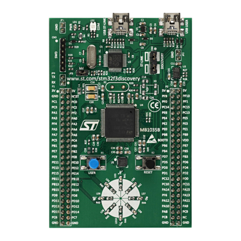
ST M24SR-DISCOVERY User manual
Other ST Motherboard manuals
ST
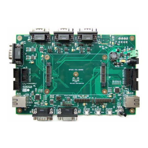
ST EVALSPEAr320PLC User manual
ST
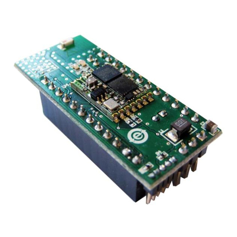
ST STEVAL-MKI132V1 User manual
ST
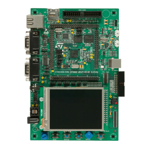
ST STM3240G-EVAL User manual
ST
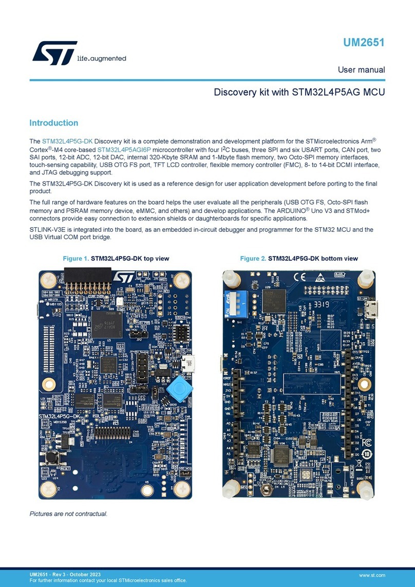
ST STM32L4P5G-DK User manual
ST
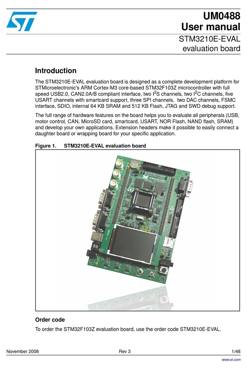
ST STM3210E-EVAL User manual
ST
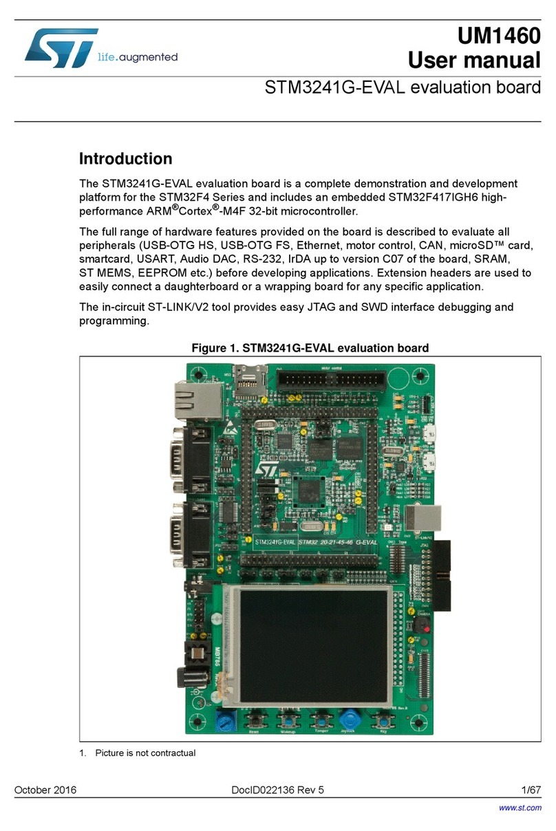
ST STM3241G-EVAL User manual
ST
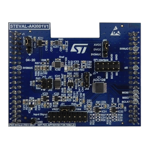
ST STEVAL-AKI001V1 User manual
ST
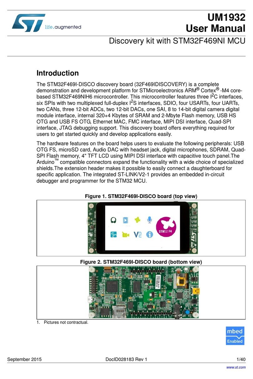
ST UM1932 User manual
ST
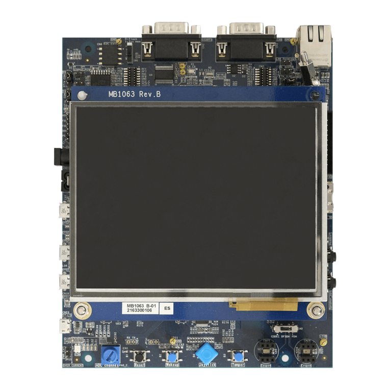
ST STM32H743I-EVAL User manual
ST
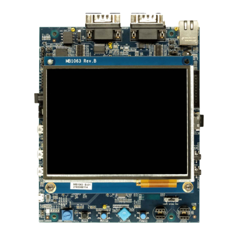
ST STM32H753I-EVAL User manual
ST
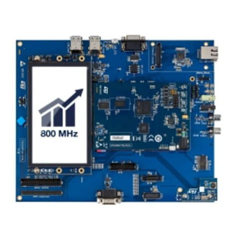
ST STM32MP157D-EV1 User manual
ST
ST UM2313 User manual
ST
ST STM32 Nucleo User manual
ST
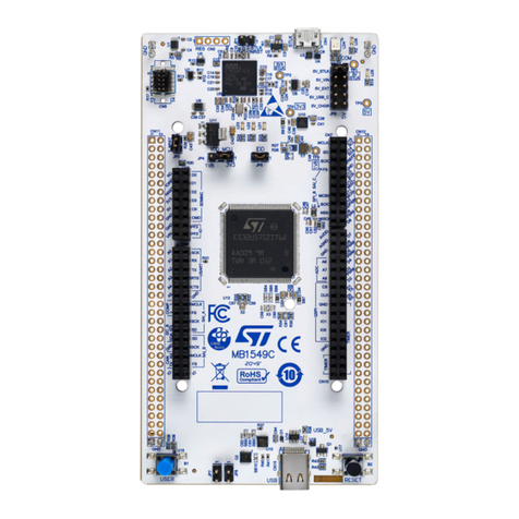
ST STM32U5 User manual
ST
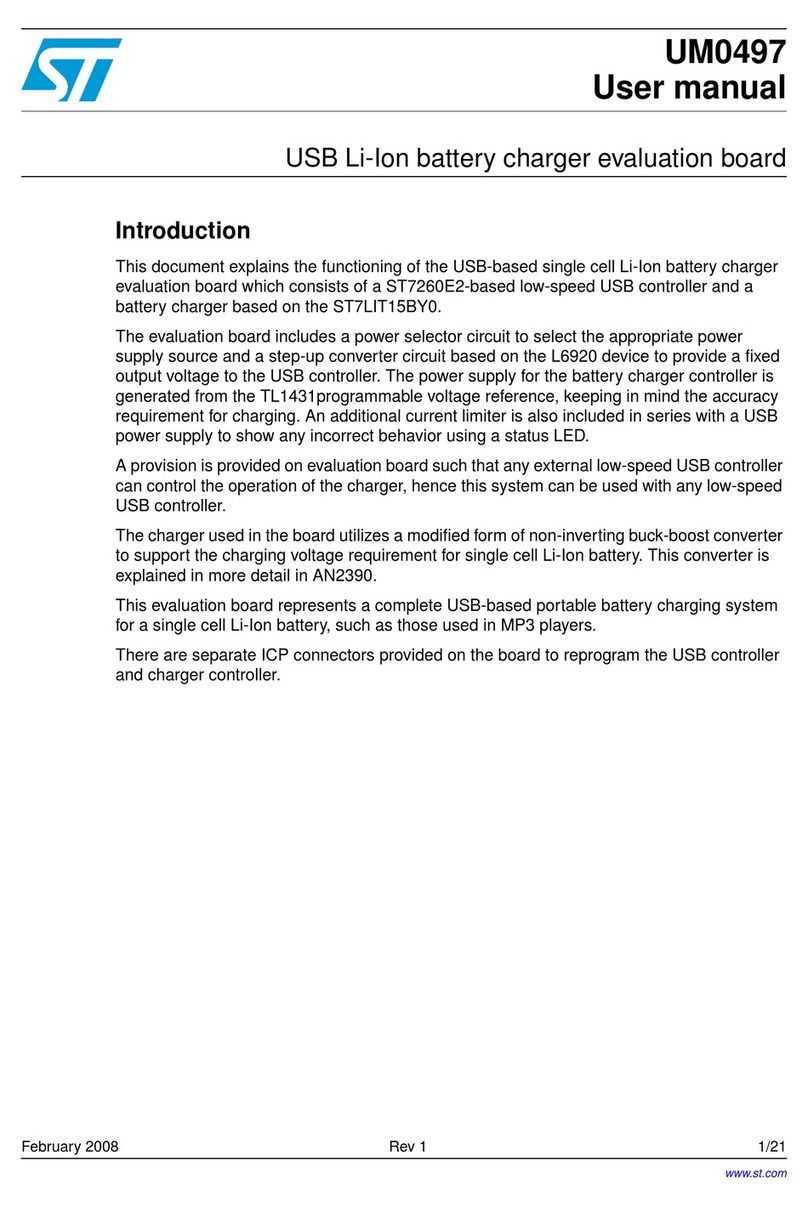
ST ST7LIT15BY0 User manual
ST
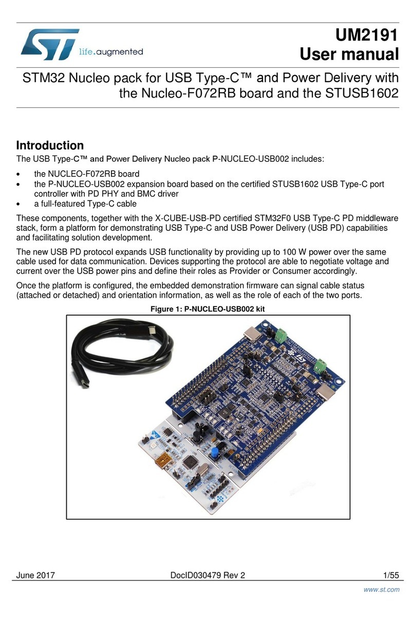
ST P-NUCLEO-USB002 User manual
ST
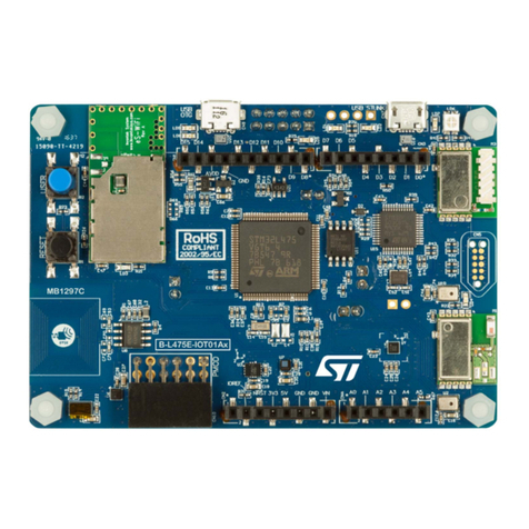
ST STM32L4 Series User manual

ST
ST STM32100B-EVAL User manual
ST
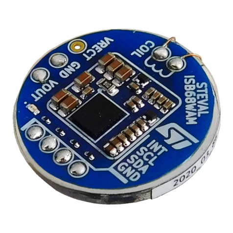
ST STEVAL-ISB68WA User manual

ST
ST AN3954 Installation and operating instructions
