Eleven Engineering SP-205 User manual

Table of Contents
1. Evaluation Kit Diagram
2. Evaluation Kit Setup
3. Evaluation Kit Features
4. Audio Test Method and Specications
5. RF Test Method and Specications
6. Sales and Support
1. Evaluation Kit Diagram
a. Antenna e. 3.5mm Stereo Audio Jack
b. SP-205 Module f. SB3 Interface Board
c. PB3 Reference Board g. Power Switch
d. Power Jack
Your kit is congured for 2-Nodes. This kit is a digital wireless audio 1.0
channel solution. Rx node has audio on left channel only.
2. Evaluation Kit Setup
This SP-205 Evaluation kit is pre-assembled and pre-congured to work of
the box. Follow the simple steps outlined below to correctly setup and
begin using the evaluation kit.
1. Plug an audio cable into the audio jack on the Transmitter (Tx). Connect the
other end of the audio cable to an audio source, such as a portable media
player (Maximum input level is -3.5dBV).
2. Plug an audio cable into the audio jack on the Receiver (Rx). Connect the
other end of the cable to an audio amplier, active speaker, or headphones.*
3. Connect the battery pack or AC adaptor (6V DC, 400mA) to the power jack on
the Tx and Rx.
4. Turn the power switches on both nodes to "on".
5. Make sure that antennas are in free space for best range, i.e. not resting
against a surface, PCB, or body.
Audio signals will begin transmission after step 4.
Please note that because this evaluation kit is electrostatic sensitive, it is
important to keep the Tx and Rx on electrostatic free surfaces.
*Headphones can be used for testing but since no headphone driver is included on the PB3 Rx board, the maximum
volume level may be lower than desired.
3. Evaluation Kit Features
The SP-205 system comes preloaded with rmware. This rmware implements
a number of useful user interface features such as LED blinking and push button
volume control. This section provides a brief summary of some commonly used
features of the rmware.
A. Bond LED: The Bond LED displays the bond status between the Tx node
and the Rx nodes, as follows:
Solid On Tx and Rx are bonded
Flashing Node is searching for bond with its mate
O Board is powered o
Bond1 LED will start to ash when the Tx is powered on. When the Rx bonds to
the Tx it will cause the Bond1 LED on the Tx and the Bond LED on the Rx to turn
solid green.
B. Mute LED: The Mute LED displays the audio status of the Rx node, as
follows:
Solid On Audio is manually muted by User
O Audio can play normally
C. Volume / Mute Control: Volume buttons on the Rx node will
increase/decrease the volume audio level by 1dB per button press for a total of
70 steps. Pressing and holding a volume button will ramp the volume quickly.
Maximum volume is 0dB and minimum volume is -70dB. NOTE: Volume
settings are stored and recalled on reboots. (Normal Default Setting: Max for left
channel)
The Volume and Mute buttons on the Tx node are currently not enabled.
D. Reset Button: Pressing the Reset button will reset the entire module.
This button is sometimes useful when downloading new rmware.
SP
SP-205 Evaluation Kit Operating Instructions
DO4611
www.ElevenEngineering.com Subject to change without notice. DO4611| 2009.11.05
@2009 Eleven Engineering Inc. XInCTM, XInC2TM and their associated logos are trademarks
of Eleven Engineering Inc. Multiple Patents and Patents Pending. Other logos, designs, titles
or phrases may be trademarks of Eleven or other entities.

E. XPD Port Interface: The XInC Programming and Debugging
(XPD) port is used to download rmware hex les to the SP module,
using an XPD Programming Module (available from Eleven
Engineering).
For more information regarding the XPD Port, XPD Module, and the
procedure for programming modules refer to the document
“Downloading Firmware to XInC Processors” (Available from Eleven
Engineering).
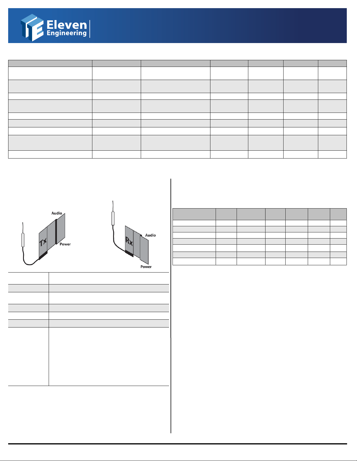
F. Multiple Systems (Sync Wire): Multiple Semi Pro
systems can be optimally congured together to operate in the same
area with minimal interference by connecting the Rx nodes together
via a sync wire. This wire will synchronize the Rx nodes when in close
proximity to eectively combine each separate Rx node into one
cohesive central hub for all SP wireless instruments on stage.
(Maximum number of systems in an area: 8)
a) Photo of sync wire setup between multiple Rx nodes.*
* Evaluation Kits may or may not be exactly as shown in photos.
SP
SP-205 Evaluation Kit Operating Instructions
DO4611
www.ElevenEngineering.com SP-205 Evaluation Kit Instructions DO4611| 2009.11.05
Page 2/4
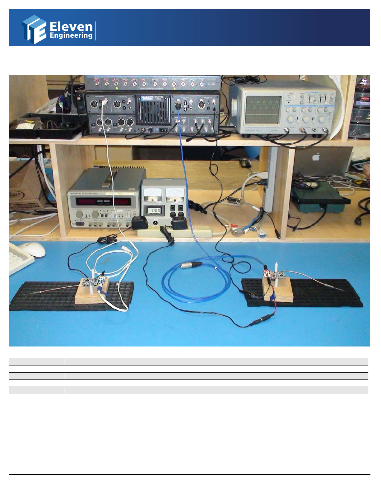
4. Audio Test Method and Specications
A. Test Method
Power Required 6V DC 400mA (one for Tx, one for Rx)
Rx Resistive Load 10 KΩ
Audio Analyzer Filters AES17 LPF “IN” unless otherwise specied
T
x Input Conditions 997Hz @ -3.5 dBV = Full Scale Input
Rx Output Level Maximum * (Set by Volume Control)
Distance Apart No closer than ~1 m **
Notes • Nodes should be tested on ESD safe surfaces and ideally elevated above surface on ESD safe mounts.
• Cables should be as far away as possible from equipment that can introduce noise into nodes. (i.e. CRT monitors, AC
Transformers, etc )
• Batteries can be used to eliminate 50/60Hz noise.
• The antenna orientation shown is for audio testing. A dierent antenna orientation may be better suited for maximum RF range
performance.
* Evaluation Kits are shipped with output level set to MAX.
** To avoid RF swamping.
SP
SP-205 Evaluation Kit Operating Instructions
DO4611
www.ElevenEngineering.com SP-205 Evaluation Kit Instructions DO4611| 2009.11.05
Page 3/4
B. Operating Conditions and Audio Characteristics
Parameter Symbol Conditions Min Typ Max Unit
Audio Input Line Level FSI VCC=3.3V 0.668 Vrms
T
x In -3.5 dBV
Audio Output Line Level FSO = FS VCC=3.3V 0.741 Vrms
(Left) Rx Out -2.59 dBV
System Gain FSI to FSO @ 997 Hz 0.91 dB
SNR A-weighted SNR Left CH RE: >92 dB FS
SNR un-weighted 997 Hz @ FS >90 dB FS
T
HD+N Left Channel THD+N 997 Hz @ -1 dB FS <0.007 %
Audio Bandwidth BW ±0.5 dB RE: 997 Hz @ FS 20 15.5K Hz
Pass Band Ripple <±0.5 dB
Bonded Current Draw Tx 131 178 229 mA
Rx 137 158 168 mA
Digital Latency * tL 9.1 ms
All measurements conducted with AES17 LPF “IN” unless other wise specied.
* Can be customer specied; latency is hard coded in the rmware.
5. RF Test Method and Specications
A. Test Method
Antenna Orientation See above diagram for orientation for maximum RF range
performance
Indoor Range* ~25 m line of sight
T
x Setup ~1.3 m high, stationary, powered with 6V DC 400mA power
adaptor
Rx Setup ~1.2 m high, mobile, powered with 4 AA batteries
Oce Space Open design with some cubicles
Oce footprint 26 m x 19 m
Notes • Antenna orientation is important to overall RF range
performance.
• Layout of the testing space aects RF performance.
Reections of the RF can cause interference.
• Obstacles such as the tester’s body, walls, and cubicles can
aect the range, wherever possible keep node antennas in
line of sight.
• Other RF devices operating in the 2.4GHz spectrum can
aect the RF performance such as microwaves, wireless
routers, and other equipment sharing the 2.4GHz band.
*Range stated is as measured in Eleven Oce Space at 9.1ms latency.
B. RF Characteristics & Behavior
The following RF characteristics include pertinent information for FCC, ETSI, and
ARIB STD T-66 regulations for RF devices.
Parameter Symbol Conditions Min Typ Max Unit
Raw Data Rate Rdr 1.536 Mbps
T
otal Channels CH 38Ch
Hopping Channels CHh 20 Ch
T
X Output Power Pout 14 15 16 dBm
Antenna Impedance ZAnt 50 Ω
Frequency Range 2.403 2.479 GHz
Indoor Range* Ri 25 m
*Range stated is as measured in Eleven Oce space at 9.1ms latency, customer range may vary (see Notes in Section
5A).
6. Sales and Support
Sales. Visit www.ElevenEngineering.com/Sales & Support/ to nd an Eleven
Technical Support. For all product questions and inquiries visit Eleven's online
support page at www.ElevenEngineering.com/Sales & Support/ or contact FAE
SP
SP-205 Evaluation Kit Operating Instructions
DO4611
www.ElevenEngineering.com SP-205 Evaluation Kit Instructions DO4611| 2009.11.05
Page 4/4
Other Eleven Engineering Motherboard manuals


