Quasar SR5133B - 51" PROJECTION TV User manual

Quasar
The service technician is required to read and follow the “Safety Precautions” and “Important Safety Notice” in this Manual.
Service Manual
Color Video Projection System
P4C
Simplified Manual
Copyright 2000 by Matsushita Electric Corporation of
America. All rights reserved. Unauthorized copying
and distribution is a violation of law.
“WARNING! This Service Manual is designed for experienced repair technicians only and is not designed for use by the general public.
It does not contain warnings or cautions to advise non-technical individuals of potential dangers in attempting to service a product.
Products powered by electricity should be serviced or repaired only by experienced professional technicians. Any attempt to
service or repair the product or products dealt with in this Service Manual by anyone else could result in serious injury or death.”
Chassis
SR5133B LP816
Models
ORDER NO. MTNC000783A1
B2
This Simplified Service Manual is issued to add listed models to the Main Service Manual order No. MTNC000211C1.
A complete parts list and service notes are included in this Simplified Manual. For Schematics please see schematics
for PT-51G35B in Simplified Service Manual order No. MTNC000234A1. Please file and use this Simplified Service
Manual together with Main Service Manual, order No. MTNC000211C1.
Simplified
- 2 -
Service Manual
Important Safety Notice
Special components are used in this projection television which are important for safety. These components are
identified on the schematic diagram by the symbol and printed in BOLD TYPE on the replacement part list. It is
essential that these critical parts are replaced with the manufacturer’s specified replacement part to prevent x-ray
radiation, shock, fire or other hazards. Do not modify the original design without the manufacturer’s permission.
Safety Precautions
General Guidelines
An
isolation transformer
should always be used
during the servicing of a PTV whose chassis is not
isolated from AC power line. Use a transformer of
adequate power rating as this protects the technician
from accidents resulting in personal injury from
electrical shocks. It will also protect the PTV from being
damaged by accidental shorting that may occur
during servicing.
When servicing, observe the original lead dress,
especially in the high voltage circuit. Replace all
damaged parts (also parts that show signs of
overheating.)
Always replace protective devices, such as
fishpaper, isolation resistors and capacitors, and
shields after servicing the PTV. Use only
manufacturer’s recommended rating for fuses, circuits
breakers, etc.
High potentials, as high as 32kV, are present when this
PTV is operating. Operation of the PTV without the rear
cover introduces danger for electrical shock. Servicing
should not be performed by anyone who is not
thoroughly familiar with the necessary precautions
when servicing high-voltage equipment.
Extreme care should be practiced when handling the
picture tube
. Rough handling may cause it to implode
due to atmospheric pressure. (14.7 lbs. per sq. in.). Do
not nick or scratch the glass or subject it to any undue
pressure. When handling, use safety goggles and
heavy gloves for protection. Discharge the picture
tube by shorting the anode to chassis ground (not to
the cabinet or to other mounting hardware). When
discharging connect cold ground (i.e. DAG ground
lead) to the anode with a well insulated wire or use a
grounding probe.
X-ray Precautions
The front area (between the projection tube and the
lens) is enclosed by a metal box to ensure positive
safety during normal and abnormal conditions when
checking and repairing. To fully ensure safety, the
following precautions must be observed.
1. Do not remove the lens or metal box.
2. Make sure to turn the power OFF when the lens is
removed or when checking the cleanliness of the
lens.
3. Do not remove the lens or metal box to check the
projection tube for operation by watching it directly.
Use a mirror or paper to view the image.
Before returning a serviced PTV to the owner, the
service technician must thoroughly test the unit to
ensure that is completely safe to operate. Do not use a
line isolation transformer when testing.
Leakage Current Cold Check
Unplug the AC cord and connect a jumper between the
two plug prongs. Press the POWER switch ON.
Measure the resistance between the jumpered AC plug
and expose metallic parts such as screw heads,
antenna terminals, control shafts, etc. If the exposed
metallic part has a return path to the chassis, the
reading should be between 240kΩ and 5.2MΩ. If the
exposed metallic part does not have a return path to
the chassis, the reading should be infinite.
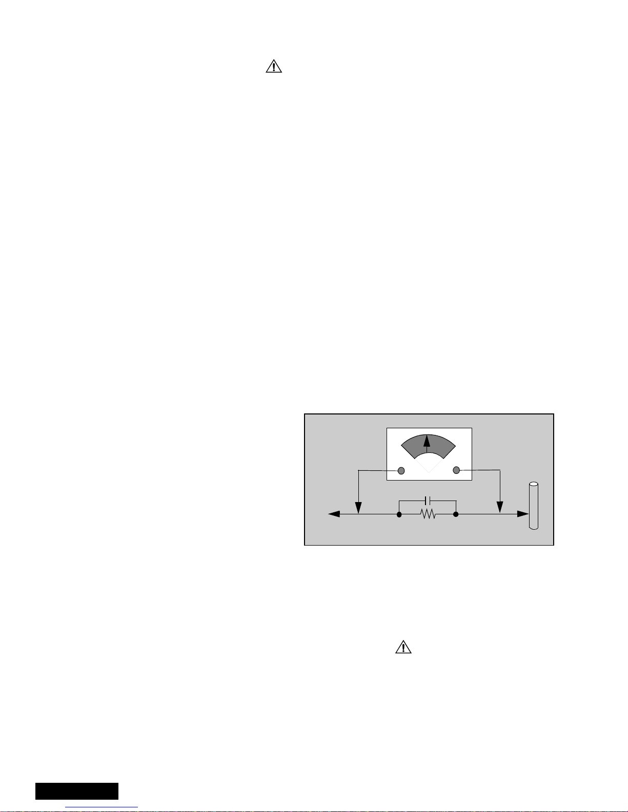
Leakage Current Hot Check (See Figure 1)
Plug the AC cord directly into the AC outlet. Do not use
an isolation transformer during the check.
Connect a 1.5kΩ10 watt resistor in parallel with a
0.15µF capacitor between and exposed metallic part
and ground. Use earth ground, for example a
water pipe.
Using a DVM with a 1000 ohms/volt sensitivity or
higher, measure the AC potential across the resistor.
Repeat the procedure and measure the voltage
present with all other expose metallic parts.
Verify any potential does not exceed 0.75 volt RMS. A
leakage current tester (such a Simpson Model 229,
Sencore Model PR57 or equivalent) may be used in
the above procedure, in which case any current
measure must not exceed 1/2 milliamp. If any
measurement is out of the specified limits, there is a
possibility of a shock hazard and the PTV must be
repaired and rechecked before it is returned to
the customer.
Insulation Test
Connect an insulation tester between an exposed
metallic part and AC line.
Apply 1080VAC/60Hz for 1 second. Confirm that the
current measurement is 0.5mA ~ 2.0mA. Repeat test
with other metallic exposed parts.
X-ray Radiation
WARNING: The potential source of X-ray radiation in the
PTV is in the high voltage section and the picture tube.
Note: It is important to use an accurate, calibrated
high voltage meter.
Set brightness, picture, sharpness and color
controls to Minimum.
Measure the High Voltage. The high should be 31.5kV
±1.0kV. If the upper limit is out of tolerance, immediate
service and correction is required to insure safe
operation and to prevent the possibility of premature
component failure.
0.15µF
Figure 1. Hot Check Circuit
COLD
WATER
PIPE
(GROUND)
TO INSTRUMENT’S
EXPOSED METAL
PARTS 1500Ω,10W
AC VOLTMETER

- 3 - Service Manual
Important Safety Tests
Measuring H.V.
The anode caps are cemented to the CRTs. To gain
access for high voltage measurement, remove the red
CRT’s anode lead from the flyback transformer (FBT)
distributor. Grasp the anode lead protective cap at its
bottom and squeeze it against the locking cap body
inside. Rotate 1/4 turn counter clockwise and pull the
anode lead sleeve out of the FBT distributor. Connect a
high voltage lead (+) from your H.V. meter to the FBT
distributor, and the common (-) to cold ground ( ).
(See Figure 2).
Note: Reinsert the anode lead into the FBT
distributor until it is tightly and fully seated.
Turn the locking cap clockwise to lock in place.
(EHT) Protector Operation Check
With the cabinet back removed, apply a nominal 120V
AC to the PTV.
Over Voltage Test
Preparation:
1. Turn PTV “OFF”
2. Connect an NTSC signal generator to the
antenna terminal.
3. Connect DVM (+) TPD4 and (-) TPD5 on D-Board.
(See Figure 3)
Figure 3. Measuring H.V.
4. Connect a H.V. meter (static type, class 0.1) with
high voltage leads to high voltage distributor
on FBT. (See Figure 4)
Figure 4. DVM connected to D-Board.
5. Connect the 8 ~ 15 V DC variable power supply to
(+) TPB10 and (-) TPBGND, on B-Board.
Procedures:
1. Apply a monoscope pattern.
2. Adjust the Picture or Brightness controls so that the
DVM reads 17.5 volts ± 0.5 volts.
3. Increase the variable power supply until set turns
off. The set should turn off at 17.5 volts ± 0.5 volts
(DVM) and high voltage less than 35.5kV.
4. If the DVM reading is other than 17.5volt (± 0.5
volts), repeat steps 2 and 3.
5. Turn off the variable supply and confirm that the set
will turn on with the Remote Control.
CRT Protect Circuit
This circuit blanks the CRT in the event that there is a
loss of vertical sweep. The circuit is not adjustable;
however the circuit should be checked each time
service is performed.
To check circuit:
1. Turn the PTV On an select an active channel.
2. Adjust Brightness and Picture controls for a visible
picture.
3. On D-Board momentarily connect a short-jumper
from TPD2 to TPDGND. The CRT should blank. If
this does not occur, repair must be performed
before returning PTV to customer.
4. Remove short-jumper.
Figure 2. Removal of FBT leads
FBT Distributor
Anode lead
Grasp protective
rubber cap
Squeeze & rotate
cap counter-
clockwise
to remove
Discharge to
CRT Chassis
3
1
2
-
+
H.V. METER
FTB Distributor
CRT
CHASSIS
-
+
DVM
TPD5 TPD4 D-Board
- 4 -
Service Manual
Important Safety Notice. . . . . . . . . . . . . . . . . . . 2
Safety Precautions . . . . . . . . . . . . . . . . . 2
Important Safety Tests . . . . . . . . . . . . . . 3
Service Notes. . . . . . . . . . . . . . . . . . . . . . . . . . . 5
PCB Designation . . . . . . . . . . . . . . . . . . . . . . . . 7
Receiver Feature Table . . . . . . . . . . . . . . . . . . . 8
Remote - Location of Controls
EUR511516. . . . . . . . . . . . . . . . . . . . . . . 9
Parts List. . . . . . . . . . . . . . . . . . . . . . . . . . . . . . 10

- 5 - Service Manual
Service Notes
Leadless Chip Component
(surface mount)
Chip components must be replaced with identical chips
due to critical foil track spacing. There are no holes in
the board to mount standard transistors or diodes.
Some chip capacitor or resistor board solder pads may
have holes through the board, however the hole
diameter limits standard resistor replacement to 1/8
watt. Standard capacitor may also be limited for the
same reason. It is recommended that identical
components be used.
Chip resistor have a three digit numerical resistance
code - 1st and 2nd significant digits and a multiplier.
Example: 162 = 1600 or 1.6kΩresistor, 0 = 0Ω (jumper).
Chip capacitors generally do not have the value
indicated on the capacitor. The color on the component
indicates the general range of the capacitance.
Chip transistors are identified by a two letter code. The
first letter indicated the type and the second letter, the
grade of transistor.
Chip diodes have a two letter identification code as per
the code chart and are a dual diode pack with either
common anode or common cathode. Check the parts
list for correct diode number.
Component Removal
1. Use solder wick to remove solder from component
end caps or terminal.
2. Without pulling up, carefully twist the component
with tweezers to break the adhesive.
3. Do not reuse removed leadless or chip
components since they are subject to stress
fracture during removal.
Chip Component Installation
1. Put a small amount of solder on the board
soldering pads.
2. Hold the chip component against the soldering
pads with tweezers or with a miniature alligator clip
and apply heat to the pad area with a 30 watts iron
until solder flows. Do not apply heat for more than
3 seconds.
How to Replace Flat-IC
- Required Tools -
1. Remove the solder from all of the pins of a Flat-IC
by using a de-solder braid.
2. Put the iron wire under the pins of the Flat-IC and
pull it in the direction indicated while heating the
pins using a soldering iron. a small awl can be
used instead of the iron wire.
3. Remove the solder from all the pads of the Flat-IC
by using a de-solder braid.
4. Position the new Flat-IC in place (apply the pins of
the Flat-IC to the soldering pads where the pins
need to be soldered). Properly determine the
position of the soldering pads and pins by correctly
aligning the polarity symbol.
5. Solder all pins to the soldering pads using a fine
tipped soldering iron.
6. Check with a magnifier for solder bridge between
the pins or for dry joint between pins and soldering
pads. To remove a solder bridge, use a de-solder
braid as shown in the figure below.
Note: These components are affixed with glue. Be careful not to break or damage any foil under the
component or at the pins of the ICs when removing. Usually applying heat to the component for
a short time while twisting with tweezers will break the component loose.
c
b
e
Chip Components
TRANSISTOR CAPACITOR
RESISTOR
MH DIODE
SOLDER
CAPS
SOLDER
CAPS
1ST DIGIT 2ND DIGIT
MULTIPLIER
=1600 = 1.6k
GRADE
TYPE
COMMON
ANODES
CATHODE
c
b
e
• Soldering iron • De-solder braids
• Iron wire or small awl • Magnifier
Flat-IC
De-Solder
Braid
Pull
Iron
Wire
Awl
Soldering
Iron
Soldering
Iron
Soldering
Iron
De-Solder
Braid
Flat IC
Polarity Symbol
Soldering
Iron
Solder
De-Solder
Braid
Solder
Braid
Soldering
Iron

- 6 -
Service Manual
Service Notes (Continued)
IMPORTANT: To protect against possible damage to
the solid state devices due to arcing or static discharge,
make certain that all ground wires and CRT DAG wire
are securely connected.
CAUTION: The power supply circuit is above earth
ground and the chassis cannot be polarized. Use an
isolation transformer when servicing the PTV to avoid
damage to the test equipment or to the chassis.
Connect the test equipment to the proper ground (( )
or ( )) when servicing, or incorrect voltages will
be measured.
WARNING: This PTV has been designed to meet or
exceed applicable safety and X-ray radiation protection
as specified by government agencies and independent
testing laboratories.
To maintain original product safety design standards
relative to X-ray radiation and shock and fire hazard,
parts indicated with the symbol on the schematic
must be replaced with identical parts. Order parts from
the manufacturer’s parts center using the parts
numbers listed in this service manual, or provide the
chassis number and the part reference number.
For optimum performance and readability, all other
parts should be replaced with components of
identical specification.

- 7 - Service Manual
PCB Designation
BOARD PART NUMBER BOARD DESCRIPTION
A-Board TXANP1A0RV Main chassis
B-Board TNPH0121AG Power supply
C-Board TNPA1513 Convergence
D-Board TNPA0609AB Protection circuit
F2-Board TNP2AA056AA Digital 3-line comb filter
G-Board TNP2AA049 Front A/V connections
K-Board TNP2AA050 Costumer controls
LB-Board TNPA0784BA Blue CRT drive
LG-Board TNPA0783BA Green CRT drive
LR-Board TNPA0782BA Red CRT drive
N-Board TNP2AA027AB 2nd tuner
R-Board TNPA0615 Remote sensor
T-Board TNP2AA045AD Line filter
X-Board TNP2AA063AB A/V inputs
Y-Board TNPA1059AC PIP processing
Table 1: PCB Designation
Note: The C & F2-Boards (TNPA1513 &
TNP2AA056AA, respectively) are Non-
Serviceable. If either board is defective,
replace the board with a new one, and return
the defective board to the Service Center.
For Schematics please refer to PT-51G35B in
Simplified Service Manual No. MTNC000234A1
Important Notice:

- 8 -
Service Manual
Receiver Feature Table
FEATURE\MODEL SR5133B
Chassis KP816
Tunning system 40K
# of channels 181
Menu language Eng/Span/F
Closed Caption X
V-Chip(USA/CANADA) X
PIP (1T), 2T PIP (2T) 2T(MITSU)
2RF X
Remote Model # EUR511516
Comb filter 3DIG
H Edge
Correction X
V/A norm Both
MTS/SAP/DBX X
AI Sound X
Spatializer X
Built-in audio
power 10W/CH (10)%
# of speakers 2
Audio out FAO:F, VAO:V F,V
A/V in (rear/front) 3 (2/1)
S-VHS in
(rear/front) 1/0
Dimension mm
(WxDxH) in 1137x651x1361.5
44.8x25.6x53.6
Weight (kg/lbs) 109/240
Power source
(V/Hz) 120V/60Hz
Anode voltage 31.5kV ± 1.0kV
Video input
jack 1Vpp 75Ω, phone jack
Audio input
jack 500mV RMS 47kΩ
Table 2: Receiver Features
Specifications are subject to change without notice or
obligation. Dimensions and weights are approximate.

- 9 - Service Manual
Remote - Location of Controls
Figure 5. Location of Controls (Remote EUR511516)
POWER Button
Press to turn ON and OFF.
MUTE Button
Press to mute sound.
A second press resumes sound.
Press also to access and delete
Closed Caption display.
VCR, DVD, TV, DBS & CBL Buttons
Component function buttons
VOL (volume) Buttons
Press to adjust TV sound level.
Use with Channel buttons to
navigate in menus.
R-TUNE (Rapid Tune) Button.
Press to switch to the previous
channel.
ACTION Button
Press to display Main Menu and access or
exit On Screen features
and Adjustment Menus.
REW, PLAY, FF, TV/VCR, STOP,
PAUSE, REC & VCR CHANNEL Buttons
Component function buttons.
DBS EXIT& DBS GUIDE Buttons
DBS function buttons.
For additional information for this and other remotes
listed in the parts list, please refer to the Remote
Guides.

- 10 -
Parts List
REPLACEMENT PARTS LIST
Models: SR5133B
Important Safety Notice: Components printed inBOLD TYPE have special characteristics important
for safety. When replacing any of these components use only manufacturer’s specified parts.
179-00
PARTS LIST
REF NO. PART NO. DESCRIPTION
CAPRISTORS
CR2801 EXNG131P365 RES-CAP 130PF/3.6 MEG
CR2802 EXNG131P365 RES-CAP 130PF/3.6 MEG
CAPACITORS
C001 ECA1CM101 CAP,E 100UF/16V
C004 TCUX1H103KBN CAP,C .01UF-K-50V
C005 ECA1CM101 CAP,E 100UF/16V
C006 ECA1HM4R7 CAP,E 4.7UF/50V
C010 ECA1CM101 CAP,E 100UF/16V
C011 ECJ2VC1H101J CAP,C 100PF-J-50V
C012 ECJ2VC1H101J CAP,C 100PF-J-50V
C013 ECA1HM220 CAP,E 22UF/50V
C014 ECA1HM220 CAP,E 22UF/50V
C015 ECJ2VC1H181J CAP,C 180PF-J-50V
C016 ECJ2VF1C105Z CAP,C 1.0UF-Z-16V
C017 ECJ2VF1C105Z CAP,C 1.0UF-Z-16V
C023 ECJ2VC1H181J CAP,C 180PF-J-50V
C024 ECA0JM102 CAP,E 1000UF/6.3V
C027 ECEA1HNR47U CAP,E .47UF-50V
C028 EEANA1E1R0B CAP,E 1.0UF-25V
C029 ECA1HM010 CAP,E 1.0UF/50V
C031 ECJ2VF1H103Z CAP,C .01UF-Z-50V
C034 ECJ2VB1H272K CAP,C .0027UF-K-50V
C039 ECJ2VC1H220J CAP,C 22PF-J-50V
C040 ECJ2VC1H270J CAP,C 27PF-J-50V
C041 ECA0JM331 CAP,E 330UF/6.3V
C042 TCUX1H103KBN CAP,C .01UF-K-50V
C043 ECJ2VF1H103Z CAP,C .01UF-Z-50V
C045 ECA1CM101 CAP,E 100UF/16V
C046 ECJ2VF1H103Z CAP,C .01UF-Z-50V
C047 ECA0JM222 CAP,E 2200UF/6.3V
C048 ECJ2VF1H103Z CAP,C .01UF-Z-50V
C049 ECA1EM101 CAP,E 100UF/25V
C050 ECA1EM471 CAP,E 470UF/25V
C051 EEUFC1E470B CAP,E 47UF-25V
C052 TACCX103T50V CAP,C .01UF/50V
C053 ECJ2VF1H103Z CAP,C .01UF-Z-50V
C054 TCUX1H103KBN CAP,C .01UF-K-50V
C055 ECJ2VF1H103Z CAP,C .01UF-Z-50V
C056 ECJ2VF1H103Z CAP,C .01UF-Z-50V
C081 ECA1HM010 CAP,E 1.0UF/50V
C101 ECJ2VF1H103Z CAP,C .01UF-Z-50V
C140 ECJ2VC1H270J CAP,C 27PF-J-50V
C301 ECEA1CN470U CAP,E 47UF-16V
C302 ECA1HM010 CAP,E 1.0UF/50V
C304 ECA1HM010 CAP,E 1.0UF/50V
C305 ECJ2VF1H103Z CAP,C .01UF-Z-50V
C306 ECA1HM220 CAP,E 22UF/50V
C307 ECJ2VF1H223Z CAP,C .022UF-Z050V
C308 ECA1HM3R3 CAP,E 3.3UF/50V
C309 ECEA1HN010U CAP,E 1UF/50V
C311 ECJ2VF1H103Z CAP,C .01UF-Z-50V
C312 ECA1HM100 CAP,E 10UF/50V
C313 ECA1VM470 CAP,E 47UF/35V
C314 ECA1CM101 CAP,E 100UF/16V
C315 ECA1EM220 CAP,E 22UF/25V
C316 ECA1HM4R7 CAP,E 4.7UF/50V
C317 ECA1HM4R7 CAP,E 4.7UF/50V
C318 ECJ2VF1H103Z CAP,C .01UF-Z-50V
C319 ECA1HM101 CAP,E 100UF/50V
C320 ECJ2VF1H103Z CAP,C .01UF-Z-50V
C321 ECA1CM101 CAP,E 100UF/16V
C330 ECJ2VC1H101J CAP,C 100PF-J-50V
C351 ECA2EM100 CAP,E 10UF/250V
C353 ECKD2H103PU CAP,C .01UF-P-500V
C354 ECA1CM101 CAP,E 100UF/16V
C356 ECKD3D332KB CAP,C .0033UF-K-2KV
C357 ECQB1H104JM CAP,P .1UF-J-50V
C359 ECKD3D102KB CAP,C .001UF-K-2KV
C360 ECA1CM470 CAP,E 47UF/16V
C361 TACCW101T50V CAP,C 100PF/50V
C363 ECKD3D102KB CAP,C .001UF-K-2KV
REF NO. PART NO. DESCRIPTION

REPLACEMENT PARTS LIST
Models: SR5133B
Important Safety Notice: Components printed inBOLD TYPE have special characteristics important
for safety. When replacing any of these components use only manufacturer’s specified parts.
- 11 -
179-00
PARTS LIST
Parts List
C364 ECA1CM470 CAP,E 47UF/16V
C365 TACCW101T50V CAP,C 100PF/50V
C366 ECEA2EU100 CAP,E 10UF/250V
C371 ECA2EM100 CAP,E 10UF/250V
C373 ECKD2H103PU CAP,C .01UF-P-500V
C374 ECA1CM101 CAP,E 100UF/16V
C376 ECKD3D332KB CAP,C .0033UF-K-2KV
C377 ECQB1H104JM CAP,P .1UF-J-50V
C379 ECKD3D102KB CAP,C .001UF-K-2KV
C380 ECA1CM470 CAP,E 47UF/16V
C381 TACCW101T50V CAP,C 100PF/50V
C382 ECKD2H103ZU CAP,C .01UF-Z-500V
C391 ECA2EM100 CAP,E 10UF/250V
C393 ECKD2H103PU CAP,C .01UF-P-500V
C394 ECA1CM101 CAP,E 100UF/16V
C396 ECKD3D332KB CAP,C .0033UF-K-2KV
C397 ECQB1H104JM CAP,P .1UF-J-50V
C401 ECJ2VB1H333K CAP,C .033UF-K-50V
C402 ECSF1EE105 CAP,T 1.0UF/25V
C403 ECSF1VE334 CAP,T .33UF/35V
C404 ECA1HM010 CAP,E 1.0UF/50V
C407 ECA1CM470 CAP,E 47UF/16V
C412 ECA1CM101 CAP,E 100UF/16V
C451 ECA1CM221 CAP,E 220UF/16V
C452 ECSF1EE105 CAP,T 1.0UF/25V
C453 ECEA1HFSR33 CAP,E .33UF/50V
C454 ECA1EHG222E CAP,E 2200UF/25V
C455 ECA1VM101 CAP,E 100UF/35V
C456 ECQM1104KZ CAP,P .1UF-K-100V
C457 ECEA1HFSR47 CAP,E .47UF/50V
C458 ECEA1HFSR47 CAP,E .47UF/50V
C459 ECA1VM471 CAP,E 470UF/35V
C460 ECQM1103KZ CAP,P .01UF-K-100V
C461 ECCD2H180JC CAP,C 18UF/500V
C463 ECQB1H103JM CAP,P .01UF-J-50V
C464 TACCX103T50V CAP,C .01UF/50V
REF NO. PART NO. DESCRIPTION
C465 ECQB1H334KF CAP,P .33UF-K-50V
C466 TACCX103T50V CAP,C .01UF/50V
C467 ECA1CM470 CAP,E 47UF/16V
C501 ECJ2VC1H182J CAP,C .0018UF-J-50V
C502 ECQB1H333JM CAP,P .033UF-J-50V
C503 ECA1HM4R7 CAP,E 4.7UF/50V
C504 ECJ2VU1H221J CAP,C 220PF-J-50V
C505 ECQB1H563JM CAP,P .056UF-J-50V
C506 ECA1HM4R7 CAP,E 4.7UF/50V
C508 ECJ2VF1H103Z CAP,C .01UF-Z-50V
C509 ECJ2VC1H820J CAP,C 82PF-J-50V
C521 ECKD2H332KB CAP,C .0033UF-K-500V
C522 ECKD2H332KB CAP,C .0033UF-K-500V
C540 ECJ2VC1H152J CAP,C .0015UF-J-50V
C541 ECJ2VC1H152J CAP,C .0015UF-J-50V
C542 ECJ2VC1H122J CAP,C .0012UF-J-50V
C551 ECKD3D221JB CAP,C 220PF-J-2KV
C552 ECKD3D152JB CAP,C .0015UF-J-2KV
C553 ECKD3D152JB CAP,C .0015UF-J-2KV
C554 ECQB1H563JM CAP,P .056UF-J-50V
C555 ECWH12H392JS CAP,P .0039UF-J-1.2KV
C556 ECKD3D181JB CAP,C 180PF-J-2KV
C557 ECWH12H103JS CAP,P .01UF-J-1.2KV
C558 ECQF4273JZH CAP,P .027UF-J-400V
C559 ECKD3D391JB CAP,C 390PF-J-2KV
C560 TAC7A2D474JC CAP,P .47UF/200V
C561 ECEA1HN2R2U CAP,E 2.2UF/50V
C564 ECEA1CN220U CAP,E 22UF-16V
C581 ECEA160V33Z CAP,E 33UF/160V
C582 ECKD2H102KB CAP,C .001UF-K-500V
C583 ECA2EM470 CAP,E 47UF-250V
C584 ECKD2H471KB CAP,C 470PF-K-500V
C585 ECA1VM102 CAP,E 1000UF/35V
C586 ECQE12473KF CAP,P .047UF-K-1.25KV
C590 ECA1HM100 CAP,E 10UF/50V
C591 ECA1CM101 CAP,E 100UF/16V
REF NO. PART NO. DESCRIPTION

- 12 -
Parts List
REPLACEMENT PARTS LIST
Models: SR5133B
Important Safety Notice: Components printed inBOLD TYPE have special characteristics important
for safety. When replacing any of these components use only manufacturer’s specified parts.
179-00
PARTS LIST
C602 ECJ2VF1H103Z CAP,C .01UF-Z-50V
C604 ECEA1HN2R2U CAP,E 2.2UF/50V
C605 TCUX1H103KBN CAP,C .01UF-K-50V
C607 ECJ2VC1H090D CAP,C 9PF-D-50V
C610 ECEA1HN010U CAP,E 1UF/50V
C611 ECEA1HN010U CAP,E 1UF/50V
C612 ECEA1HN010U CAP,E 1UF/50V
C614 ECJ2VF1H104Z CAP,C .1UF-Z-50V
C615 ECJ2VC1H330J CAP,C 33PF-J-50V
C616 TCUX1H103KBN CAP,C .01UF-K-50V
C617 ECJ2VF1H103Z CAP,C .01UF-Z-50V
C620 ECEA1HN010U CAP,E 1UF/50V
C621 ECEA1HN010U CAP,E 1UF/50V
C625 TCUX1H103KBN CAP,C .01UF-K-50V
C626 ECUX1H391JCX CAP,C 390PF-J-50V
C650 ECA1HM100 CAP,E 10UF/50V
C653 ECA1HM010 CAP,E 1.0UF/50V
C654 ECA1HM010 CAP,E 1.0UF/50V
C709 ECA1HM010 CAP,E 1.0UF/50V
C751 ECQE1335KF CAP,P 3.3UF-K-100V
C752 ECA1CM101 CAP,E 100UF/16V
C756 ECA1CM101 CAP,E 100UF/16V
C804 ECKD2H103ZF CAP,C .01UF-Z-500V
C805 ECKD2H103ZF CAP,C .01UF-Z-500V
C806 ECKD2H103ZF CAP,C .01UF-Z-500V
C809 ECQB1H223JM CAP,P .022UF-J-50V
C815 ECQB1H152JM CAP,P 1500PF-J-50V
C816 EC0S2DA471BB CAP,E 470UF/160V
C817 EC0S2DA471BB CAP,E 470UF/160V
C818 ECKD3A392KB CAP,C 3900PF-K-1KV
C819 ECQB1H102JM CAP,P 1000PF-J-50V
C820 ECA1VM470 CAP,E 47UF/35V
C821 ECQB1H102JM CAP,P 1000PF-J-50V
C822 TACCW391T50V CAP,C 390PF/50V
C823 ECQB1H471JF CAP,P .0047UF-J-50V
C824 ECEA1VGE101 CAP,E 100UF/35V
REF NO. PART NO. DESCRIPTION
C825 ECQB1H473JM CAP,P .047UF-J-50V
C826 ECQB1H683JM CAP,P .068UF-J-50V
C827 ECQB1H104JM CAP,P .1UF-J-50V
C828 ECQB1H473JM CAP,P .047UF-J-50V
C829 ECKCNB472ME CAP,C 4700PF-M-250V
C830 ECKCNB472ME CAP,C 4700PF-M-250V
C831 ECKD3D681KB CAP,C 680PF-K-2KV
C832 ECES2DU221E4 CAP,E 220UF/200V
C833 ECKD3A471KB CAP,C 470PF-K-1KV
C834 ECA1EM102 CAP,E 1000UF/25V
C835 ECKD3A471KB CAP,C 470PF-K-1KV
C836 ECA1CM102 CAP,E 1000UF/16V
C837 ECKD3A471KB CAP,C 470PF-K-1KV
C838 ECA1VM222 CAP,E 2200UF/35V
C839 ECKD3A471KB CAP,C 470PF-K-1KV
C840 ECA1VM222 CAP,E 2200UF/35V
C841 ECKD3A471KB CAP,C 470PF-K-1KV
C842 ECA1HM102 CAP,E 1000UF/50V
C844 ECKD3D681KB CAP,C 680PF-K-2KV
C845 ECQB1H104JM CAP,P .1UF-J-50V
C846 ECA1CM101 CAP,E 100UF/16V
C847 ECA0JM331 CAP,E 330UF/6.3V
C848 ECA1CM101 CAP,E 100UF/16V
C850 ECA1EM220 CAP,E 22UF/25V
C851 ECA1CM470 CAP,E 47UF/16V
C852 ECA1CM470 CAP,E 47UF/16V
C870 ECKCNB472ME CAP,C 4700PF-M-250V
C880 ECA1CM101 CAP,E 100UF/16V
C881 ECA1CM101 CAP,E 100UF/16V
C882 ECA1CM101 CAP,E 100UF/16V
C883 ECA1CM101 CAP,E 100UF/16V
C889 ECJ2VF1H103Z CAP,C .01UF-Z-50V
C890 ECJ2VF1H103Z CAP,C .01UF-Z-50V
C941 ECA1CM100 CAP,E 10UF/16V
C942 ECJ2VF1H473Z CAP,C .047UF-Z-50V
C944 TCUX1H103KBN CAP,C .01UF-K-50V
REF NO. PART NO. DESCRIPTION

REPLACEMENT PARTS LIST
Models: SR5133B
Important Safety Notice: Components printed inBOLD TYPE have special characteristics important
for safety. When replacing any of these components use only manufacturer’s specified parts.
- 13 -
179-00
PARTS LIST
Parts List
C956 ECQM2103JZ CAP,P .01UF-J-200V
C957 TACCX103T50V CAP,C .01UF/50V
C958 TACCX102T50V CAP,C .1UF/50V
C959 TACCW102T50V CAP,C .001UF/50V
C961 ECA0JM101 CAP,E 100UF/6.3V
C962 ECA0JM101 CAP,E 100UF/6.3V
C963 ECA0JM101 CAP,E 100UF/6.3V
C964 ECA0JM101 CAP,E 100UF/6.3V
C965 ECA2CM100 CAP,E 10UF-160V
C966 ECA2CM100 CAP,E 10UF-160V
C967 ECKD2H472MD CAP,C .0047UF-M-500V
C968 ECA0JM101 CAP,E 100UF/6.3V
C973 ECCD2H151J CAP,C 150PF-J-500V
C974 ECCD2H151J CAP,C 150PF-J-500V
C975 TACCW101T50V CAP,C 100PF/50V
C976 TACCW101T50V CAP,C 100PF/50V
C977 TACCW101T50V CAP,C 100PF/50V
C978 TACCW101T50V CAP,C 100PF/50V
C1149 ECJ2VF1H103Z CAP,C .01UF-Z-50V
C1551 ECEA1EN101U CAP,E 100UF-25V
C1552 ECA1CM101 CAP,E 100UF/16V
C1553 ECQB1H683JM CAP,P .068UF-J-50V
C1571 ECKD2H181KB CAP,C 180PF-K-500V
C1572 ECEA1HN100U CAP,E 10UF/50V
C1582 ECA1HM470 CAP,E 47UF/50V
C1583 ECA1HM220 CAP,E 22UF/50V
C1584 ECA1VM470 CAP,E 47UF/35V
C1585 ECA1CM221 CAP,E 220UF/16V
C1586 TACCX103T50V CAP,C .01UF/50V
C1587 ECA1HM4R7 CAP,E 4.7UF/50V
C1588 ECJ2VF1H103Z CAP,C .01UF-Z-50V
C1607 ECA1CM101 CAP,E 100UF/16V
C1608 ECJ2VC1H101J CAP,C 100PF-J-50V
C1609 ECJ2VC1H101J CAP,C 100PF-J-50V
C1801 ECJ2VF1H103Z CAP,C .01UF-Z-50V
C1802 ECQV1H154JM CAP,P .15UF-J-50V
REF NO. PART NO. DESCRIPTION
C1803 ECEA1HKAR22 CAP,E .22UF/50V
C1804 ECEA1HKAR22 CAP,E .22UF/50V
C1805 ECJ2VF1H333Z CAP,C .033UF-Z-50V
C1806 ECJ2VF1H103Z CAP,C .01UF-Z-50V
C1807 ECEA1CKA470 CAP,E 47UF/16V
C1808 ECJ2VF1H103Z CAP,C .01UF-Z-50V
C1809 ECEA1CKA470 CAP,E 47UF/16V
C1810 ECJ2VF1H104Z CAP,C .1UF-Z-50V
C1811 ECJ2VF1H103Z CAP,C .01UF-Z-50V
C1812 ECJ2VF1H103Z CAP,C .01UF-Z-50V
C1813 ECJ2VF1H103Z CAP,C .01UF-Z-50V
C1814 ECEA1CKA470 CAP,E 47UF/16V
C1815 ECJ2VF1H104Z CAP,C .1UF-Z-50V
C1816 ECJ2VF1H103Z CAP,C .01UF-Z-50V
C1817 ECJ2VF1H103Z CAP,C .01UF-Z-50V
C1818 ECEA1CKA100 CAP,E 10UF/16V
C1819 ECJ2VF1H104Z CAP,C .1UF-Z-50V
C1820 ECEA1CKA470 CAP,E 47UF/16V
C1821 ECJ2VC1H150J CAP,C 15PF-J-50V
C1822 ECJ2VC1H120J CAP,C 12PF-J-50V
C1823 ECJ2VC1H680J CAP,C 68PF-J-50V
C1826 ECJ2VF1H103Z CAP,C .01UF-Z-50V
C1827 ECJ2VF1H103Z CAP,C .01UF-Z-50V
C1828 ECJ2VF1H103Z CAP,C .01UF-Z-50V
C1829 ECJ2VF1H104Z CAP,C .1UF-Z-50V
C1830 ECJ2VC1H560J CAP,C 56PF-J-50V
C1831 ECJ2VF1H104Z CAP,C .1UF-Z-50V
C1832 ECJ2VF1H104Z CAP,C .1UF-Z-50V
C1833 ECJ2VF1H104Z CAP,C .1UF-Z-50V
C1835 ECEA1CKA100 CAP,E 10UF/16V
C1836 ECJ2VC1H680J CAP,C 68PF-J-50V
C1837 ECJ2VF1H104Z CAP,C .1UF-Z-50V
C1839 ECJ2VC1H680J CAP,C 68PF-J-50V
C1840 ECJ2VC1H680J CAP,C 68PF-J-50V
C1901 ECA1HM100 CAP,E 10UF/50V
C1902 ECQB1H223JM CAP,P .022UF-J-50V
REF NO. PART NO. DESCRIPTION

- 14 -
Parts List
REPLACEMENT PARTS LIST
Models: SR5133B
Important Safety Notice: Components printed inBOLD TYPE have special characteristics important
for safety. When replacing any of these components use only manufacturer’s specified parts.
179-00
PARTS LIST
C1903 ECA1CM101 CAP,E 100UF/16V
C1917 ECA1HM3R3 CAP,E 3.3UF/50V
C2101 ECA1CM101 CAP,E 100UF/16V
C2105 ECA1CM101 CAP,E 100UF/16V
C2106 ECA1HM4R7 CAP,E 4.7UF/50V
C2108 ECA1CM101 CAP,E 100UF/16V
C2109 ECJ2VF1H103Z CAP,C .01UF-Z-50V
C2111 ECEA1HFSR22 CAP,E .22UF/50V
C2115 ECA1HM100 CAP,E 10UF/50V
C2116 ECJ2VF1H103Z CAP,C .01UF-Z-50V
C2117 ECJ2VC1H270J CAP,C 27PF-J-50V
C2118 ECJ2VC1H270J CAP,C 27PF-J-50V
C2119 ECJ2VF1H103Z CAP,C .01UF-Z-50V
C2120 ECEA1HFSR47 CAP,E .47UF/50V
C2121 ECJ2VF1H103Z CAP,C .01UF-Z-50V
C2123 ECJ2VC1H270J CAP,C 27PF-J-50V
C2124 ECJ2VF1H103Z CAP,C .01UF-Z-50V
C2126 ECA1HMR22 CAP,E .22UF/50V
C2130 ECJ2VF1H103Z CAP,C .01UF-Z-50V
C2301 ECQB1H474JF CAP,P .47UF-J-50V
C2302 ECQB1H474JF CAP,P .47UF-J-50V
C2303 ECJ2VC1H561J CAP,C 560PF-J-50V
C2304 ECJ2VC1H561J CAP,C 560PF-J-50V
C2305 ECJ2VF1H104Z CAP,C .1UF-Z-50V
C2306 ECJ2VF1H104Z CAP,C .1UF-Z-50V
C2307 ECJ2VB1H472K CAP,C .0047UF-K-50V
C2308 ECJ2VB1H472K CAP,C .0047UF-K-50V
C2309 ECJ2VC1H101J CAP,C 100PF-J-50V
C2310 ECJ2VC1H101J CAP,C 100PF-J-50V
C2311 ECJ2VF1H473Z CAP,C .047UF-Z-50V
C2312 ECJ2VF1H473Z CAP,C .047UF-Z-50V
C2313 ECJ2VF1H104Z CAP,C .1UF-Z-50V
C2314 ECJ2VF1H104Z CAP,C .1UF-Z-50V
C2315 ECJ2VF1H104Z CAP,C .1UF-Z-50V
C2316 ECA1HM221 CAP,E 220UF/50V
C2317 ECJ2VF1H104Z CAP,C .1UF-Z-50V
REF NO. PART NO. DESCRIPTION
C2318 ECA1HM221 CAP,E 220UF/50V
C2319 ECJ2VF1H104Z CAP,C .1UF-Z-50V
C2320 ECJ2VF1H104Z CAP,C .1UF-Z-50V
C2321 ECEA1HN2R2U CAP,E 2.2UF/50V
C2323 ECA1VM222 CAP,E 2200UF/35V
C2324 ECA1VM222 CAP,E 2200UF/35V
C2325 ECA1VM222 CAP,E 2200UF/35V
C2326 ECA1VM222 CAP,E 2200UF/35V
C2327 ECEA1CKN100 CAP,E 10UF/16V
C2328 ECEA1CKN100 CAP,E 10UF/16V
C2331 ECJ2VF1H103Z CAP,C .01UF-Z-50V
C2332 ECJ2VF1H103Z CAP,C .01UF-Z-50V
C2333 ECEA1CKN100 CAP,E 10UF/16V
C2334 ECEA1CKN100 CAP,E 10UF/16V
C2335 ECJ2VF1H103Z CAP,C .01UF-Z-50V
C2339 ECJ2VF1H104Z CAP,C .1UF-Z-50V
C2340 ECJ2VF1H104Z CAP,C .1UF-Z-50V
C2341 ECJ2VC1H221J CAP,C 220PF-J-50V
C2342 ECJ2VC1H221J CAP,C 220PF-J-50V
C2351 ECA1EM101 CAP,E 100UF/25V
C2352 ECJ2VF1H103Z CAP,C .01UF-Z-50V
C2401 ECJ2VB1E473K CAP,C .047UF-K-25V
C2402 ECJ2VB1H153K CAP,C .015UF-K-50V
C2403 ECJ2VB1E473K CAP,C .047UF-K-25V
C2404 TCUX1H103KBN CAP,C .01UF-K-50V
C2405 ECJ2VB1C104K CAP,C .1UF-I-16V
C2406 ECJ2VB1H153K CAP,C .015UF-K-50V
C2407 ECEA1HN100U CAP,E 10UF/50V
C2408 ECA1HM100 CAP,E 10UF/50V
C2409 ECA1HM100 CAP,E 10UF/50V
C2410 ECA1HM100 CAP,E 10UF/50V
C2411 ECA1HM100 CAP,E 10UF/50V
C2412 ECA1HM100 CAP,E 10UF/50V
C2413 ECA1HM0R1 CAP,E 0.1UF/50V
C2414 ECA1HM100 CAP,E 10UF/50V
C2415 ECA1CM101 CAP,E 100UF/16V
REF NO. PART NO. DESCRIPTION

REPLACEMENT PARTS LIST
Models: SR5133B
Important Safety Notice: Components printed inBOLD TYPE have special characteristics important
for safety. When replacing any of these components use only manufacturer’s specified parts.
- 15 -
179-00
PARTS LIST
Parts List
C2416 ECA1HM0R1 CAP,E 0.1UF/50V
C2417 ECA1HMR47 CAP,E .47UF/50V
C2418 ECA1CM101 CAP,E 100UF/16V
C2419 ECA1HM100 CAP,E 10UF/50V
C2420 ECA1HM100 CAP,E 10UF/50V
C2421 ECEA1HN100U CAP,E 10UF/50V
C2422 ECA1HM100 CAP,E 10UF/50V
C2423 ECA1HM010 CAP,E 1.0UF/50V
C2424 ECA1HM010 CAP,E 1.0UF/50V
C2425 ECA1HM100 CAP,E 10UF/50V
C2426 ECEA1HN100U CAP,E 10UF/50V
C2427 ECEA1HN100U CAP,E 10UF/50V
C2428 ECA1HM100 CAP,E 10UF/50V
C2429 ECA1HM010 CAP,E 1.0UF/50V
C2430 ECA1HM010 CAP,E 1.0UF/50V
C2431 ECEA1HN220U CAP,E 22UF/50V
C2802 ECQU2A224MV CAP,P .22UF-M-250VAC
C2807 ECA1EM471 CAP,E 470UF/25V
C2808 TACCW103T50V CAP,C .01UF/50V
C3001 ECA1CM101 CAP,E 100UF/16V
C3002 ECJ2VF1H103Z CAP,C .01UF-Z-50V
C3003 ECEA1HN010U CAP,E 1UF/50V
C3004 ECA1VM470 CAP,E 47UF/35V
C3005 ECA1CM101 CAP,E 100UF/16V
C3006 ECA1HM100 CAP,E 10UF/50V
C3007 ECA1HM100 CAP,E 10UF/50V
C3008 ECA1HM010 CAP,E 1.0UF/50V
C3009 ECA1HM010 CAP,E 1.0UF/50V
C3010 ECA1CM101 CAP,E 100UF/16V
C3011 ECA1CM101 CAP,E 100UF/16V
C3040 ECJ2VC1H101J CAP,C 100PF-J-50V
C3041 ECA1HM100 CAP,E 10UF/50V
C3054 ECA1CM471 CAP,E 470UF/16V
C3071 ECJ2VF1H103Z CAP,C .01UF-Z-50V
C3072 ECA1HM100 CAP,E 10UF/50V
C3073 ECA1HM100 CAP,E 10UF/50V
REF NO. PART NO. DESCRIPTION
C3074 ECA1HM010 CAP,E 1.0UF/50V
C3075 ECA1HM010 CAP,E 1.0UF/50V
C3078 ECA1HM100 CAP,E 10UF/50V
C3079 ECA1HM010 CAP,E 1.0UF/50V
C3080 ECA1HM010 CAP,E 1.0UF/50V
C3301 ECA1HM100 CAP,E 10UF/50V
C4101 ECJ2VF1H103Z CAP,C .01UF-Z-50V
C4107 ECJ2VC1H331J CAP,C 330PF-J-50V
C4108 ECJ2VF1H103Z CAP,C .01UF-Z-50V
C4109 ECJ2VC1H271J CAP,C 270PF-J-50V
C4110 ECA1HM100 CAP,E 10UF/50V
C4111 ECA1CM101 CAP,E 100UF/16V
C4112 ECA1CM101 CAP,E 100UF/16V
C4123 ECA1CM101 CAP,E 100UF/16V
C4131 ECJ2VC1H820J CAP,C 82PF-J-50V
C4141 ECJ2VC1H820J CAP,C 82PF-J-50V
C4142 ECJ2VF1H103Z CAP,C .01UF-Z-50V
C4151 ECJ2VC1H820J CAP,C 82PF-J-50V
C4251 ECJ2VF1H104Z CAP,C .1UF-Z-50V
C4301 ECKF1H103ZF CAP,C .01UF-Z-50V
C4302 ECJ2VF1H103Z CAP,C .01UF-Z-50V
C4303 ECJ2VC1H101J CAP,C 100PF-J-50V
C4304 ECEA1CKA100 CAP,E 10UF/16V
C4307 ECEA1CKN100 CAP,E 10UF/16V
C4313 ECJ2VB1H561K CAP,C 560PF-K-50V
C4314 ECEA1HKAR47 CAP,E .47UF/50V
C4315 ECJ2VB1H152K CAP,C .0015UF-K-50V
C4316 ECEA0JKA331 CAP,E 330UF/6.3V
C4317 ECJ2VF1H103Z CAP,C .01UF-Z-50V
C4318 ECEA0JKA101 CAP,E 100UF/6.3V
C4319 ECUX1H391JCX CAP,C 390PF-J-50V
C7001 ECA1HM2R2 CAP,E 2.2UF/50V
C7002 ECA1HM2R2 CAP,E 2.2UF/50V
C7003 ECA1HM101 CAP,E 100UF/50V
C7004 ECA1HM101 CAP,E 100UF/50V
C7005 ECA1HM101 CAP,E 100UF/50V
REF NO. PART NO. DESCRIPTION

- 16 -
Parts List
REPLACEMENT PARTS LIST
Models: SR5133B
Important Safety Notice: Components printed inBOLD TYPE have special characteristics important
for safety. When replacing any of these components use only manufacturer’s specified parts.
179-00
PARTS LIST
C7006 ECA1HM101 CAP,E 100UF/50V
C7009 ECJ2VC1H151J CAP,C 150PF-J-50V
C7010 ECJ2VC1H151J CAP,C 150PF-J-50V
C7011 ECJ2VC1H151J CAP,C 150PF-J-50V
C7012 ECJ2VC1H151J CAP,C 150PF-J-50V
C7013 ECJ2VC1H151J CAP,C 150PF-J-50V
C7014 ECJ2VC1H151J CAP,C 150PF-J-50V
C7015 ECJ2VF1H103Z CAP,C .01UF-Z-50V
C7016 ECJ2VF1H103Z CAP,C .01UF-Z-50V
C7017 ECJ2VF1H103Z CAP,C .01UF-Z-50V
C7018 ECJ2VF1H103Z CAP,C .01UF-Z-50V
C7031 ECA1CM101 CAP,E 100UF/16V
C7032 ECJ2VF1C105Z CAP,C 1.0UF-Z-16V
C7033 ECJ2VC1H821J CAP,C 820UF-J-50V
C7034 ECJ2VF1H104Z CAP,C .1UF-Z-50V
C7035 ECJ2VF1C105Z CAP,C 1.0UF-Z-16V
C7036 ECJ2VC1H102J CAP,C .001UF-J-50V
C7037 ECJ2VF1H104Z CAP,C .1UF-Z-50V
C7038 ECJ2VF1C105Z CAP,C 1.0UF-Z-16V
C7039 ECJ2VF1C105Z CAP,C 1.0UF-Z-16V
C7051 ECA1HM100 CAP,E 10UF/50V
C7052 ECA1VM470 CAP,E 47UF/35V
C7053 ECEA1CN101U CAP,E 100UF-16V
DIODES
D004 MA4330H DIODE
D005 MA4056M DIODE
D014 MA4051M DIODE
D015 MA4051M DIODE
D097 MA152K DIODE
D098 MA152K DIODE
D351 ERA15-10 DIODE
D353 MA165 DIODE
D354 MA165 DIODE
D355 MA165 DIODE
D356 MA165 DIODE
D357 MA165 DIODE
REF NO. PART NO. DESCRIPTION
D358 AU01Z DIODE
D359 MA165 DIODE
D360 MA165 DIODE
D361 MA165 DIODE
D363 MA4091M DIODE, ZENER
D364 MA167 DIODE
D371 ERA15-10 DIODE
D373 MA165 DIODE
D374 MA165 DIODE
D375 MA165 DIODE
D376 MA165 DIODE
D377 MA165 DIODE
D378 AU01Z DIODE
D391 ERA15-10 DIODE
D393 MA165 DIODE
D394 MA165 DIODE
D395 MA165 DIODE
D396 MA165 DIODE
D397 MA165 DIODE
D398 AU01Z DIODE
D399 TVSRM1 DIODE
D451 ERA15-01 DIODE
D452 MA2330-B DIODE
D453 MA2330-B DIODE
D454 MA4360M DIODE
D455 MA4062L DIODE
D456 MA4062L DIODE
D457 MA4120M DIODE
D458 MA165 DIODE
D459 MA165 DIODE
D460 MA165 DIODE
D461 MA165 DIODE
D462 MA165 DIODE
D463 MA165 DIODE
D464 MA165 DIODE
D530 MA4039H DIODE, ZENER
REF NO. PART NO. DESCRIPTION

REPLACEMENT PARTS LIST
Models: SR5133B
Important Safety Notice: Components printed inBOLD TYPE have special characteristics important
for safety. When replacing any of these components use only manufacturer’s specified parts.
- 17 -
179-00
PARTS LIST
Parts List
D531 MA3039H DIODE
D532 MA4062L DIODE
D541 MA152K DIODE
D551 RH3FLFS1 DIODE
D552 S2L60P1518 DIODE
D553 MA4270M DIODE
D561 MA165 DIODE
D562 MA4039M DIODE, ZENER
D564 MA165 DIODE
D565 MA152K DIODE
D581 ERA22-04 DIODE, ZENER
D582 AU02 DIODE
D583 RP1H DIODE
D650 MA4110M DIODE, ZENER
D651 MA4110M DIODE, ZENER
D652 MA4110M DIODE, ZENER
D659 MA4110M DIODE, ZENER
D660 MA4110M DIODE, ZENER
D661 MA4051M DIODE
D662 MA4110M DIODE, ZENER
D663 MA4110M DIODE, ZENER
D664 MA4051M DIODE
D751 MA3047M DIODE, ZENER
D756 MA165 DIODE
D758 MA4030L DIODE, ZENER
D760 MA152K DIODE
D802 RBV-408 BRIDGE, RECTIFIER
D804 MA165 DIODE
D816 MA700 DIODE
D817 AU01Z DIODE
D818 MA4220L DIODE, ZENER
D819 TMPG10G3 DIODE
D821 MA165 DIODE
D822 ERA22-02 DIODE
D831 RU30ALFS1 DIODE, RECTIFIER
D832 RU3YX-M DIODE
REF NO. PART NO. DESCRIPTION
D833 RU3YX-MLF-C4 DIODE
D834 RL3ZLFS1 DIODE
D835 RL3ZLFS1 DIODE
D836 RL4ZLF-L1 DIODE
D837 MA165 DIODE
D838 MA4047L DIODE, ZENER
D839 MA4033M DIODE, ZENER
D840 MA167 DIODE
D841 MA165 DIODE
D842 MA4082M DIODE
D843 MA165 DIODE
D844 MA4020 DIODE
D847 MA165 DIODE
D848 MA165 DIODE
D849 MA165 DIODE
D954 MA4360M DIODE
D955 MA4360M DIODE
D956 MA28WTX DIODE
D957 MA165 DIODE
D958 MA165 DIODE
D959 MA165 DIODE
D960 MA165 DIODE
D1110 MA152K DIODE
D1117 MA3051 DIODE
D1551 MA165 DIODE
D1552 MA29-B DIODE
D1571 MA165 DIODE
D1581 AS01 DIODE
D1583 MA4062L DIODE
D1584 MA4330M DIODE
D1585 MA4330M DIODE
D1587 MA3082M DIODE
D2102 MA4330H DIODE
D2307 MA152K DIODE
D2352 MA152K DIODE
D2353 MA152K DIODE
REF NO. PART NO. DESCRIPTION

- 18 -
Parts List
REPLACEMENT PARTS LIST
Models: SR5133B
Important Safety Notice: Components printed inBOLD TYPE have special characteristics important
for safety. When replacing any of these components use only manufacturer’s specified parts.
179-00
PARTS LIST
D2801 ERZC10VK361G VARISTOR
D2802 ERA15-01 DIODE
D2803 ERA15-01 DIODE
D2804 ERA15-01 DIODE
D2805 ERA15-01 DIODE
D3001 MA3110M DIODE, ZENER
D3002 MA3051M DIODE
D3004 MA3051M DIODE
D3006 MA3110M DIODE, ZENER
D3007 MA3051M DIODE
D3009 MA3051M DIODE
D3051 MA3110M DIODE, ZENER
D3071 MA3110M DIODE, ZENER
D3072 MA3110M DIODE, ZENER
D3073 MA3110M DIODE, ZENER
D3074 MA3110M DIODE, ZENER
D3075 MA3110M DIODE, ZENER
D4103 MA152K DIODE
D4104 MA152K DIODE
D4105 MA152K DIODE
D4106 MA3056M DIODE
D4107 MA152K DIODE
D4109 MA152K DIODE
D4110 MA152K DIODE
D4111 MA152K DIODE
D4112 MA152K DIODE
D4134 MA152K DIODE
D4144 MA152K DIODE
D4154 MA152K DIODE
D4301 MA3036H DIODE
D7031 MA3091M DIODE
D7051 MA152K DIODE
D7052 MA152K DIODE
FUSES
F2801 0BA1C63NU100 FUSE (6.3A-125V)
REF NO. PART NO. DESCRIPTION
INTEGRATED CIRCUITS
IC001 MN102L35GTS INT CKT
IC002 M24C08-WBN6 INT CKT
IC005 AN78M05 PLUS 5V AVR
IC006 MN1280R INT CKT
IC301 AN5308NK INT CKT
IC451 LA7838 INT CKT
IC452 BA15218N INT CKT
IC801 AN8026 INT CKT
IC802 SE139NLF4 ERROR AMP
IC811 TLP621GR PHOTO COUPLER
IC831 AN7812 INT CKT
IC832 AN7809 INT CKT
IC833 SI-3050CA INT CKT
IC834 AN79M12 INT CKT
IC1601 MC14066BFEL INT CKT
IC1801 M65617SP INT CKT
IC2101 AN5170K INT CKT
IC2301 TDA7480 INT CKT
IC2302 TDA7480 INT CKT
IC2401 AN7396K INT CKT
IC2402 BA15218N INT CKT
IC3001 CXA2079Q INT CKT
IC3301 AN5862K INT CKT
IC6505 PQ3RD13B INT CKT
IC7001 STK392-110 INT CKT
IC7002 STK392-110 INT CKT
COILS
LC3201 EXCEMT101BTS L-C NETWORK
LC3202 EXCEMT101BTS L-C NETWORK
LC3203 EXCEMT101BTS L-C NETWORK
LC3204 EXCEMT101BTS L-C NETWORK
L001 ELESN390KA COIL, PEAKING 39UH
L002 EXCELSA35 FERRITE BEAD
L010 EXCELSA35 FERRITE BEAD
REF NO. PART NO. DESCRIPTION

REPLACEMENT PARTS LIST
Models: SR5133B
Important Safety Notice: Components printed inBOLD TYPE have special characteristics important
for safety. When replacing any of these components use only manufacturer’s specified parts.
- 19 -
179-00
PARTS LIST
Parts List
L012 TLUABTA100K COIL, PEAKING 10UH
L013 TLUABTA100K COIL, PEAKING 10UH
L015 TLUABTA100K COIL, PEAKING 10UH
L016 TLUABTA100K COIL, PEAKING 10UH
L017 EXCELSA35T FERRITE BEAD
L140 ELESN330KA COIL, PEAKING 33UH
L351 ELEBD101KA COIL, PEAKING 100UH
L352 TLTACT820K COIL, PEAKING 82UH
L353 TLTACT820K COIL, PEAKING 82UH
L354 TLTACT820K COIL, PEAKING 82UH
L355 EXCELSA35T FERRITE BEAD
L371 ELEBD101KA COIL, PEAKING 100UH
L372 TLTACT820K COIL, PEAKING 82UH
L373 TLTACT820K COIL, PEAKING 82UH
L374 TLTACT820K COIL, PEAKING 82UH
L375 EXCELSA35T FERRITE BEAD
L376 ELEBD101KA COIL, PEAKING 100UH
L391 ELEBD101KA COIL, PEAKING 100UH
L392 TLTACT820K COIL, PEAKING 82UH
L393 TLTACT820K COIL, PEAKING 82UH
L394 TLTACT820K COIL, PEAKING 82UH
L395 EXCELSA35T FERRITE BEAD
L552 EXCELSA35B FERRITE BEAD
L553 EXCELSA35B FERRITE BEAD
L581 EXCELDR35C FERRITE BEAD
L601 TLUABTA820K COIL, PEAKING 82UH
L602 TLTACT4R7J COIL, PEAKING 4.7UH
L751 TLH15733M COIL, TOP/BOTTOM PHASING
L805 EXCELSA35T FERRITE BEAD
L806 EXCELSA35T FERRITE BEAD
L808 EXCELDR35 FERRITE BEAD
L810 EXCELSA35T FERRITE BEAD
L811 EXCELSA35T FERRITE BEAD
L812 EXCELSA35B FERRITE BEAD
L831 EXCELSA35B FERRITE BEAD
L832 EXCELSA39E FERRITE BEAD
REF NO. PART NO. DESCRIPTION
L833 TLP15103S COIL, CHOKE
L834 EXCELSA35T FERRITE BEAD
L835 EXCELSA35T FERRITE BEAD
L836 EXCELSA35T FERRITE BEAD
L837 EXCELSA35T FERRITE BEAD
L838 EXCELSA35T FERRITE BEAD
L839 EXCELSA35T FERRITE BEAD
L841 ELEIN220KA FILTER CHOKE
L842 ELEIN220KA FILTER CHOKE
L843 EXCELSA35T FERRITE BEAD
L953 EXCELSA35T FERRITE BEAD
L954 EXCELSA35T FERRITE BEAD
L956 ELESN101JA COIL, PEAKING 100UH
L960 TLTACT1R0K COIL, PEAKING 1UH
L1109 TLTACT100J COIL, PEAKING 10UH
L1110 TLTACT100K COIL, PEAKING 10UH
L1801 ELESN1R5KA COIL, PEAKING 1.5UH
L1803 ELESN2R2K COIL, PEAKING 2.2UH
L1804 ELESN150KA COIL, PEAKING 15UH
L1806 ELESN1R0KA COIL, PEAKING 1.0UH
L1807 ELESN1R0KA COIL, PEAKING 1.0UH
L1808 EXCELDR25 FERRITE BEAD
L2102 TLTACT100K COIL, PEAKING 10UH
L2103 TLTACT150K COIL, PEAKING 15UH
L2104 TLTACT330K COIL, PEAKING 33UH
L2105 TLTACT1R2K COIL, PEAKING 1.2UH
L2106 TLTACT560K COIL, PEAKING 56UH
L2107 TLTACT1R2K COIL, PEAKING 1.2UH
L2109 EIV7EN053B COIL, VCO
L2112 EXCELSA35 FERRITE BEAD
L2301 ELC10E680 FILTER
L2302 ELC10E680 FILTER
L2303 EXCELDR35 FERRITE BEAD
L2304 EXCELDR35 FERRITE BEAD
L2801 ELF18D850B LINE FILTER
L2802 ELF18D650M CHOKE, AC LINE
REF NO. PART NO. DESCRIPTION

- 20 -
Parts List
REPLACEMENT PARTS LIST
Models: SR5133B
Important Safety Notice: Components printed inBOLD TYPE have special characteristics important
for safety. When replacing any of these components use only manufacturer’s specified parts.
179-00
PARTS LIST
L3006 TLTACT100K COIL, PEAKING 10UH
L3301 TLTACT330K COIL, PEAKING 33UH
L3309 TLTACT100K COIL, PEAKING 10UH
L3333 TLTACT100K COIL, PEAKING 10UH
L4301 ELESN3R9KA COIL, PEAKING 3.9UH
L7032 TLTACT1R0K COIL, PEAKING 1UH
TRANSISTORS
Q011 2SB709ARTX TRANSISTOR
Q012 2SB709ARTX TRANSISTOR
Q013 2SB709ARTX TRANSISTOR
Q014 2SD601ARTX TRANSISTOR
Q031 2SB709ARTX TRANSISTOR
Q032 2SD601ARTX TRANSISTOR
Q33 2SB709ARTX TRANSISTOR
Q099 2SB709ARTX TRANSISTOR
Q140 2SD601ARTX TRANSISTOR
Q141 2SD601ARTX TRANSISTOR
Q142 2SB709ARTX TRANSISTOR
Q301 2SB709ARTX TRANSISTOR
Q303 2SB709ARTX TRANSISTOR
Q304 2SD601ARTX TRANSISTOR
Q306 2SD601ARTX TRANSISTOR
Q308 2SB709ARTX TRANSISTOR
Q309 2SD601ARTX TRANSISTOR
Q310 2SD601ARTX TRANSISTOR
Q353 2SC3063 TRANSISTOR
Q354 2SC3063 TRANSISTOR
Q355 2SB1011 TRANSISTOR
Q356 2SB1011 TRANSISTOR
Q373 2SC3063 TRANSISTOR
Q374 2SC3063 TRANSISTOR
Q375 2SB1011 TRANSISTOR
Q376 2SB1011 TRANSISTOR
Q393 2SC3063 TRANSISTOR
Q394 2SC3063 TRANSISTOR
Q395 2SB1011 TRANSISTOR
REF NO. PART NO. DESCRIPTION
Q396 2SB1011 TRANSISTOR
Q397 2SC1473A TRANSISTOR
Q398 2SC1473A TRANSISTOR
Q410 2SD601ARTX TRANSISTOR
Q411 2SD601ARTX TRANSISTOR
Q451 2SC1685QRS TRANSISTOR
Q452 2SC1685QRS TRANSISTOR
Q453 2SC1685QRS TRANSISTOR
Q501 2SC4212H TRANSISTOR
Q504 2SD601ARTX TRANSISTOR
Q505 2SD601ARTX TRANSISTOR
Q551 2SD2553MA TRANSISTOR
Q561 2SC1685QRS TRANSISTOR
Q602 2SB709ARTX TRANSISTOR
Q603 2SB709ARTX TRANSISTOR
Q604 2SD601ARTX TRANSISTOR
Q605 2SD601ARTX TRANSISTOR
Q701 2SB709ARTX TRANSISTOR
Q751 2SD1499P TRANSISTOR
Q752 2SA564AQRSTA TRANSISTOR
Q753 2SC1685QRS TRANSISTOR
Q801 FS18SM-10-AB TRANSISTOR
Q802 2SC1685QRS TRANSISTOR
Q803 2SA564AQRSTA TRANSISTOR
Q810 2SC1685QRS TRANSISTOR
Q831 2SA19610QAHW TRANSISTOR
Q832 2SA564AQRSTA TRANSISTOR
Q833 2SC1473RTA TRANSISTOR
Q834 2SB709ARTX TRANSISTOR
Q951 2SC1685QRS TRANSISTOR
Q952 2SD601ARTX TRANSISTOR
Q953 2SB709ARTX TRANSISTOR
Q954 2SB940P TRANSISTOR
Q955 2SD1264P TRANSISTOR
Q956 2SB940P TRANSISTOR
Q957 2SD1264P TRANSISTOR
REF NO. PART NO. DESCRIPTION
This manual suits for next models
1
Table of contents


