QUATRO
Air Technologies Inc.
DFH-1000 ---------------------------------------------------------------------------------------------------------------------We Make Clean Air
2
1.0 SAFETY PRECAUTIONS
- Read instructions contained in this manual before operating unit. Keep manual, as it contains information for proper operation and
maintenance. Keep all fastening hardware tight to ensure unit is in safe working condition.
- Familiarize yourself with the way in which filters are removed, installed, and serviced. All filters must be in place whenever this
machine is in operation.
- Use only on a grounded electrical circuit; do not use any two-wire electrical prong adapters to defeat the three-pronged plug on the
end of the cord.
- When servicing the motor, be careful when touching the exterior of the motor as soon as it has been turned off; it may be hot
enough to be painful or cause injury, they are built to operate at higher temperatures.
- Do not substitute any other filters for those supplied as this will alter the design characteristics.
WARNING: Switch unit off and unplug power cord from wall before servicing the blower.
2.0 UNIT RECEIVING INSTRUCTIONS
2.1 UNIT INSPECTION
Upon receipt, inspect unit for either visible or concealed damage. Damage should be immediately reported to the transport company.
Included in shipment is:
- main filter/blower section - exhaust hood (shipped loose) - wall support plate (shipped loose).
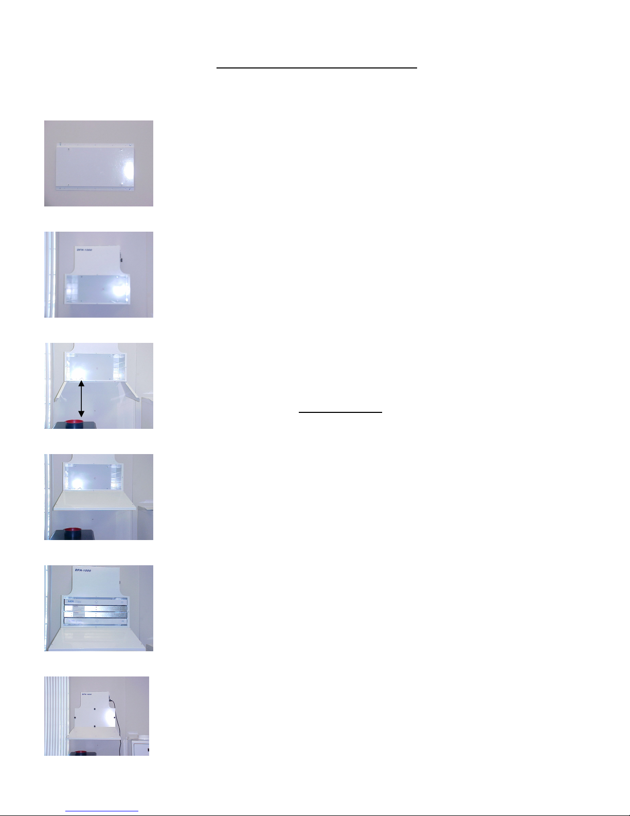
2.2 INSTALLATION
PRIOR TO INSTALLATION, OPEN THE DOOR TO THE PURIFIER AND REMOVE ALL FILTERS. This will make is easier to lift the
unit into position.
a) INSTALL FUME HOOD MINIMUM 10” ABOVE THE BURNOUT OVEN
(see Note 4 on page 4) (distance from top of DFH to ceiling: 3” minimum).
b) INSTALL BURNOUT OVEN UNDER CENTER OF HOOD.
c) DFH-1000 IS DESIGNED TO OPERATE WITH ONE BURNOUT OVEN.
EXHAUSTING TO THE OUTSIDE: DFH can be connected to existing ductwork for venting to
outdoors. To do this, purchase AA088-Exhaust kit, & replace top grille with with 6” dia. Collar Plate supplied in
the kit (using same 4 screws). Connect collar plate to exhaust ductwork. (AA088 comes with discharge plate, 6ft
of 6” dia. Hose & clamps)
Unit to wall installation:
a) WALL SUPPORT PLATE is c/w top and bottom wall flange each having (11) holes, 2” center to center;
b) center to center distance from top hole to bottom hole is 20”;
c) WALL SUPPORT PLATE can be mounted onto the wall using the following:
Wood stud wall: use (6) wood screws (minimum 3” long number #8);
Concrete or block wall: use (4) concrete screws (3/16x2.5”);
Drywall: use (6) appropriate screws with proper anchors;
d) locate the WALL SUPPORT PLATE on the wall;
e) drill 2 level pilot holes for top flange, and (2) for the bottom flange;
f) line-up the PLATE such that 2 of the (11) holes line up over the 2 pilot holes;
g) screw the top flange of the PLATE into the wall;
h) line up bottom and screw in the bottom PLATE;
i) INSTALL DFH FILTER/BLOWER section ONTO WALL SUPPORT PLATE using (4) bolts supplied, through the inside of
filter section and (4) nuts/bolts supplied with the unit on the outer side of the filter section;
j) Ensure that BAFFLE PLATE underneath the filters is properly placed within its frame
This BAFFLE PLATE ensures that fumes from burn-out oven spread out evenly through-out filter section;
k) Re-install all the filters;
l) Secure the exhaust hood to the main filter/blower section using nuts/bolts provided.
m) Replace filters back into the unit: DFH-1000-B: (F007, F033-GPB,F033-APC, F022 from bottom to top)
DFH-1000-M: (F007, F033-GPB,F033-BPC, F007 from bottom to top)
DFH-1000-D: (F007, F022 from bottom to top)
2.3 PRE START-UP CHECKLIST
a) All internal components are present and are adequately supported;
b) Labels and serial numbers are present for future identification;
c) Verify that the power supply is compatible with the equipment (120-volt/1 phase/60 hz). Also check that the unit is plugged into a
grounded receptacle;
d) Ensure all wrapping has been removed from filters prior to installing filters into DFH.