qubev smart EVON0090 User manual

INSTALLATION & OPERATION MANUAL
Intelligent Electric
Vehicle Chargepoints
7.4kW or 22kW Models
Support
Intelligent Electric Vehicle Chargepoints QUBEVSM-V01-R0 Installation and Operation Manual
Page 1of 42 February 2023
Amendments
Amendment
Number Details Date
Ver 1, Rev 0 New Document. February
2023
Product: Intelligent Electric Vehicle Chargepoints
Applicable Models:
1-Phase 3-Phase
EVON0090 – Socket Version EVON0100 – Socket Version
EVON0095 – Tethered Version EVON0105 – Tethered Version
Document Type: Installation and Operation Manual
Document Code: QUBEVSM-V01-R0
Language: UK English (Original)
Date Published: February 2023
One Stop Europe Ltd are the publishers of this document and own the rights to use the text, images and all technical content
contained within. Content supplied by third parties / partner organisations remains the property of that organisation and is used by
agreement with the supplier.
OneStop exercise care to ensure content is as accurate as possible at the time of publication. However, no guarantee of accuracy
should be inferred.
www.qubev.com
One Stop Europe Ltd
Ralphs Lane, Frampton West, Boston, Lincolnshire, PE20 1QU

Support
QUBEVSM-V01-R0 Installation and Operation Manual Intelligent Electric Vehicle Chargepoints
February 2023 Page 2of 42
Contents
Support 2
Safety 3
Safety Advice within this Manual 3
Product Features 4
About Load Balancing 4
About Demand Side Response 4
About PEN Protection 5
Product Specification 6
Physical Specification 6
Electrical Specification 8
Certifications and Compliances 8
Labelling 9
Unpacking 9
Typical Contents 9
Typical Options 9
Installation 10
Before Installation 10
If a Mounting Post Will be Used 12
Schematic Diagrams 13
Installation Procedure 15
Install Load Balancing 18
Overview 18
Connect the CT to the Property 18
Connect a 3-Phase CT to the Property 19
Extend the CT Cable 19
Solar Integration 20
Connect the CT Cable to the Chargepoint 20
Configure Load Balancing 21
Install Cable Tidy/Hanger 22
Testing 23
Application Setup 24
Register 24
Add a Device 25
Remove a Device 26
Functional Check 27
Configure Load Balancing 28
Change the Load Balancing Setting 30
OCPP IP and ID Settings 31
Operation 31
Share a Connection 31
Charger Status Indications 33
Operational Indications 33
Fault Indications 33
Charger Button Functions 34
Charge a Vehicle 35
Charging Modes 35
Plug and Charge 35
Schedule Mode 36
Create a Schedule: 37
Delete a Schedule 37
ECO Mode 38
Other Application Features 39
Edit Charger Details 39
Record Screen 39
Maintenance 40
Disposal 41
Warranty 42
Support
For assistance with the installation or operation of this product, contact your preferred electrical
installer.

Safety
Intelligent Electric Vehicle Chargepoints QUBEVSM-V01-R0 Installation and Operation Manual
Page 3of 42 February 2023
Safety
This manual is provided as a guide to installation and operation and is specifically applicable to
the QubEV Intelligent electric vehicle charger. Failure to install and operate the QubEV in
accordance with these instructions may damage the unit and invalidate the manufacturer’s
warranty.
IMPORTANT: Installers and End Users must read and understand the content of
this manual before installation and/or use of the product.
Installation must only be performed by someone who is properly qualified and competent to do
so in accordance with the current legislation in force in the geographical location of the
installation.
xThe manufacturer/distributor cannot accept any responsibility for improper installation or
any problems arising from improper installation.
NOTE: Damage to the equipment, connected systems or to property caused by improper
installation are the responsibility of the installer.
xThe information provided in this manual must ONLY be used with the model(s) listed on
page 1 of this manual.
xThe information provided in this manual must NOT be used with any other product.
xThe content of this manual may be updated by the manufacturer as required.
xDo NOT use the equipment for anything other than its intended purpose.
xDo NOT modify the equipment unless specifically instructed to do so by the manufacturer.
xDo NOT attempt to repair the equipment unless specifically instructed to do so by the
manufacturer.
xTo maintain electrical safety, the body enclosure of the product (access covers) must be
secured in their correct location using the supplied fasteners and the seal must be
sufficient to maintain the IP rating of the enclosure.
xFasteners used to mount the product in its working location must be sufficient for the
task and the specific mounting point.
xIf required, fasteners used to mount the product in its working location should be sealed
to maintain the IP rating of the enclosure.
xDamage to the product may render it unsafe. The product must be electrically isolated and
NOT used until appropriate remedial action has been performed.
Safety Advice within this Manual
This manual uses a system of warnings, cautions and notes.
xWARNINGS concern the safety of installers/end user and will be given before the
detail/instructions in the manual.
xCAUTIONS concern the potential for damage to the equipment and will be given before the
detail/instructions in the manual.
xNOTES are given to provide additional information and/or to highlight information of
importance. They will be given either before or after the detail/instructions as appropriate
and may use different wording (such as IMPORTANT) where emphasis is required.
Warnings, Cautions and Notes may be repeated several times as appropriate and may be
preceded by a hazard symbol where appropriate.

Product Features
QUBEVSM-V01-R0 Installation and Operation Manual Intelligent Electric Vehicle Chargepoints
February 2023 Page 4of 42
Product Features
xUniversal charging socket or Type 2 tethered
lead
xPower rating – Up to 7.4kW or 22kW models
xAdjustable power rating – 10A, 13A, 16A &
32A
xFree QUBEV Smart Wi-Fi app
xScheduled / off-peak charging
xSolar compatible*
xPEN fault and residual current protection (AC
30mA Type A, DC 6mA)
xDynamic load balancing (CT clamp(s) &
cable(s) included)
xOCPP 1.6 compliant
xBuilt-in LED charging status indicator
xUK Smart Charge Point Regulations
Compliant including tamper security
xWi-Fi / Ethernet connectivity
xIP54 & IK08 rated
xCorrosion & fire resistant
xCE and UKCA certified
xEasy to install and maintain
xWall or post mounting options
x3 Year warranty
*App dependent features:
NOTE: When detailing Load Balancing, this manual assumes the installation of a single
chargepoint. Whilst multiple chargepoints can be connected in a similar way, installers may
wish to consider connecting/monitoring using a third-party, compliant energy management
solution.
If connecting/monitoring via third-party equipment, make sure you are fully aware of the
manufacturer’s instructions so that the device/system can be installed correctly and in
conjunction with the chargepoint installation.
About Load Balancing
This chargepoint has a Load Balancing capability which is designed to prevent overloads of the
property’s power supply when a vehicle is being charged.
Once correctly installed and configured, the system will monitor the power being drawn by the
charging process and will compare this to the permissible maximum for the property as a whole
(which is set as part of the configuration). With this information, the power made available for
charging can be dynamically adjusted to reduce the load before the property’s maximum load is
exceeded.
NOTES:
xLoad balancing ONLY controls power made available to the VEHICLE. It does not control
power to other equipment and it is still possible for that equipment to overload the
property’s power supply.
xDepending on the manufacturer, electric vehicles need a minimum of around 6 Amps to
charge. If the available power is below this level, the vehicle may stop the charge session.
xThe lower the power available for charging, the more slowly the vehicle will be charged.
About Demand Side Response
Demand Side Response (DSR) is where the chargepoint and the electricity provider are in
communication with each other. The electricity provider will control the chargepoint remotely via

Product Features
Intelligent Electric Vehicle Chargepoints QUBEVSM-V01-R0 Installation and Operation Manual
Page 5of 42 February 2023
the chargepoint software to reduce the power it draws when it is needed by higher priorities in the
area and will increase power when those priorities reduce.
If the chargepoint is used with a DSR agreement in place, peak and off-peak charging will not be
implemented because the power company’s systems will control the charging process.
About PEN Protection
The PEN protection system removes the need to install a dedicated earth for the chargepoint
although an earth is still required via the power cable.
In the event of a fault, the system will break all power cable connections between the chargepoint
and the vehicle.

Product Specification
QUBEVSM-V01-R0 Installation and Operation Manual Intelligent Electric Vehicle Chargepoints
February 2023 Page 6of 42
Product Specification
Physical Specification
Enclosure Dimensions 330mm x 200mm x109mm (H x W x D)
Enclosure Materials PC/ABS Alloy
Mass
x2.5kg 1-Phase, Single Socket
x2.75kg 3-Phase, Single Socket
x4.7kg 1-Phase, Tethered Cable
x6.0kg 3-Phase, Tethered Cable
Operating Temperature -25°C to +50°C
Humidity 3%~95%
Altitude <2000m
Protection
xIP65 – Enclosure Ingress
xIP54 – Socket/Plug Ingress
xUL94-V0 Fire Rated
xIK08 Impact
Figure 1 Enclosure Dimensions
Product Specification
Intelligent Electric Vehicle Chargepoints QUBEVSM-V01-R0 Installation and Operation Manual
Page 7of 42 February 2023
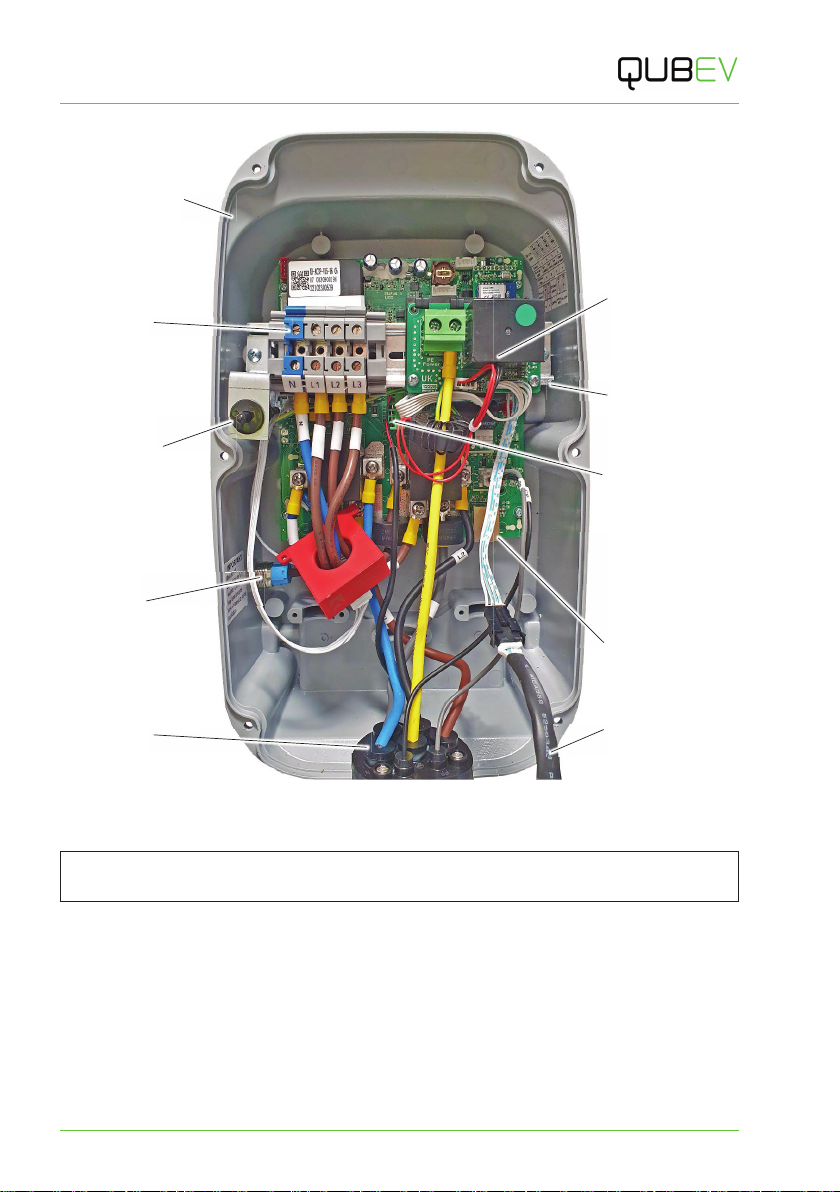
Figure 2 Internal Arrangement (3-phase, socket model shown)
NOTE: Except for the number of incoming power terminals, the internal arrangements of all
models are very similar.
Rear Enclosure
Incoming
Power
Terminals
Anti-tamper
Switch
Socket
Terminals LED Indicator
Cable
Ethernet Port for
OCCP
Communications
External CT
Connector
DIP Switches
Below PEN Module
PEN Module
Function
Button
Product Specification
QUBEVSM-V01-R0 Installation and Operation Manual Intelligent Electric Vehicle Chargepoints
February 2023 Page 8of 42
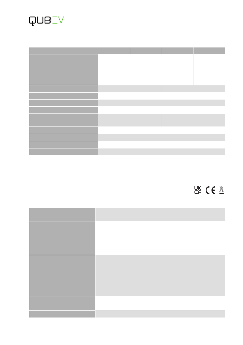
Electrical Specification
EVON0090 EVON0095 EVON0100 EVON0105
Description Single
Socket,
Intelligent
EV Charging
Unit
5m Tethered
Cable,
Intelligent
EV Charging
Unit
Single
Socket,
Intelligent
EV Charging
Unit
5m Tethered
Cable,
Intelligent
EV Charging
Unit
Rated Output Up to 7.4kW (32A) Up to 22kW (32A)
Rated Current Up to 32A max
DC Fault Protection Type A 30mA, DC 6mA
Charging Current Variable – 10A, 13A, 16A, & 32A
Input Voltage AC 220V~240V 50/60Hz
(1-phase)
AC380V~415V 50/60Hz
(3-phase)
Incoming Cable Terminals 3 x 10mm2 terminals 5 x 10mm2 terminals
Overcurrent Protection Recommended 40A
Charging Connection IEC 62196 (Type 2)
Charge Protocol Mode 3
NOTES:
1. A Type ‘A’ Residual Current Circuit Breaker (RCBO) installed at source is recommended.
2. Tethered cables are approximately 5m total length.
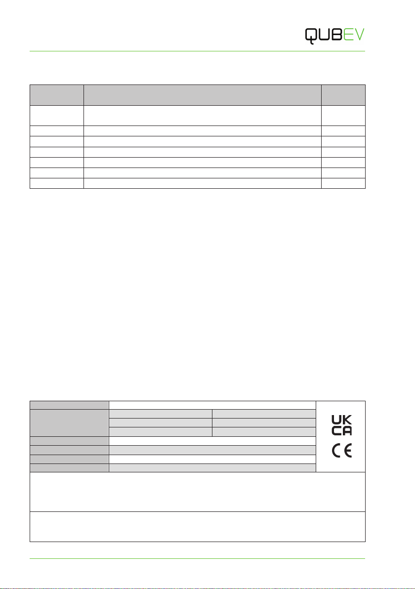
Certifications and Compliances
This product has been designed and built in accordance with the following standards and
legislation:
EV Charging Compliance EN IEC 61851-1:2019, BS EN IEC 61851-1:2019.
Smart Regulations SI 2021:1467 inc Schedule 1.
EMC Compliance 2014/30/EU, SI 2016:1091.
ETSI EN 301 489-1 V2.2.3 (2019-11) ETSI EN 301 489-3 V2.1.1
(2019-03), ETSI EN 301 489-17 V3.2.4 (2020-09).
IEC 61851-21-2:2018.
EN IEC 61851-21-2:2021.
Radio Emissions 2014/53/EU, SI 2021:1467.
ETSI EN 300 328 V2.2.2, ETSI EN 300 330 V2.1.1.
ETSI EN 301 489-1 V2.2.3, ETSI EN 301 489-3 V2.1.1.
ETSI EN 301 489-17 V3.2.4, EN IEC 61851-21-2:2021.
EN IEC 61851-1:2019, EN IEC 62311:2020.
BS EN IEC 61851-21-2:2021, BS EN IEC 62311:2020.
Safety Compliance EN 60950-1:2006+A2:2013, EN 60950-22:2017.
IEC 62955:2018.
Low Voltage Directive (LVD) 2014/35/EU, SI 2016:1101.
Labelling
Intelligent Electric Vehicle Chargepoints QUBEVSM-V01-R0 Installation and Operation Manual
Page 9of 42 February 2023
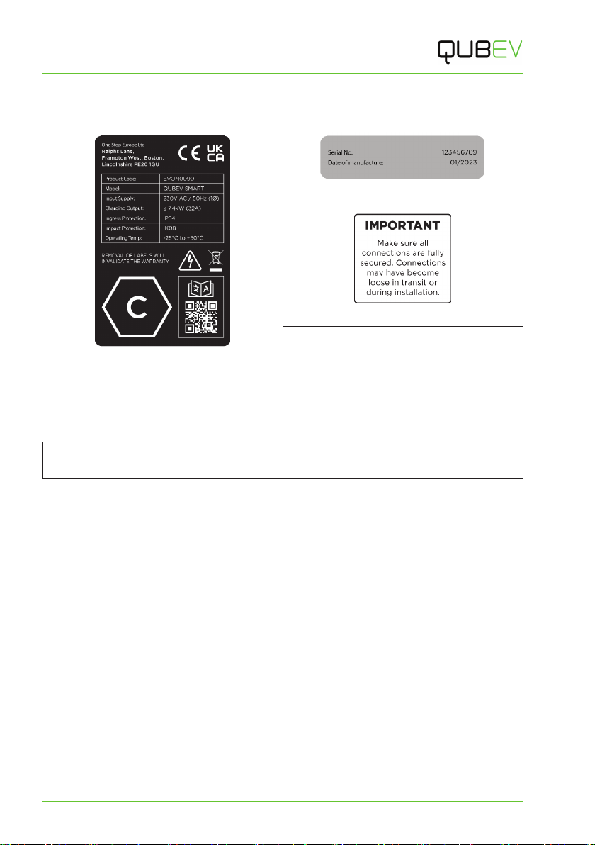
Labelling
Observe any/all warning labels displayed on or inside the enclosure.
Figure 3 Typical Product Label
Figure 4 Typical Serial Number Label
Includes Month and Year of Manufacture
Figure 5 Terminal Security Label
NOTE: The Connection Type marking
(hexagon) is shown on the charger of socket
models, and on the plug of tethered cable
models.
Unpacking
The content of the package depends on any options or accessories that may have been selected.
IMPORTANT: Make sure all packaging is disposed of responsibly and in accordance with the
current regulations in your region.
Typical Contents
x1 x EV Charging Device and Fixing Bracket.
x1 x Installation and Operation Manual.
x1 x Hex Wrench.
x4 x Wiring Ferules.
x1 x Cable Gland and Rubber Sealing Grommet.
x1 x Charger Fixing Kit (4 x Fixings and Wall Plugs).
x1 x Cable Tidy/Hanger and Fixings (Tethered Cable Chargers Only).
x1 x Load Balancing CT Device.
x1 x Load Balancing CT Device Terminal Block.
x1 x Load Balancing CT Device Rubber Sealing Grommet.
Typical Options
xEV charging cables (Type 1 to Type 2 or Type 2 to Type 2).
xCharge point signage.
xType A Residual Current Circuit Breaker (RCBO).
xEnclosure for Residual Current Circuit Breaker.

Installation
QUBEVSM-V01-R0 Installation and Operation Manual Intelligent Electric Vehicle Chargepoints
February 2023 Page 10 of 42
Installation
IMPORTANT: Installers and End Users must read and understand the content of
this manual before installation and/or use of the product.
Installation must only be performed by someone who is properly qualified and competent to do
so in accordance with the current legislation in force in the geographical location of the
installation.
xAdvice provided in this manual does NOT replace any legislation.
xThe manufacturer/distributor cannot accept any responsibility for improper installation
or any problems arising from improper installation.
NOTE: Damage to the equipment, connected systems or to property caused by improper
installation are the responsibility of the installer.
Before Installation
1. Discuss with the customer where the chargepoint is to be installed. This may affect
whether the electrical power cable will enter the unit from below or behind the enclosure.
xCable entry through the left, right or top of the enclosure is NOT recommended.
xIf Load Balancing will be implemented, the charge point should, ideally, be within the
reach of the Load Balancing Device cable which must be connected between the
chargepoint and the property’s main consumer unit (fuse box). Load Balancing Device
cables can be extended if required.
xIf Load Balancing will be implemented, plan the installation of the Load Balancing
Device alongside the installation of the chargepoint. Information about installing load
balancing is shown after the chargepoint installation.
2. Identify an installation location for the unit that is both secure and environmentally safe.
xIf installing a tethered cable version of the charger, also decide where the cable
tidy/hanger will be mounted.
xWhilst the chargepoint is weather resistant in accordance with the required
standards, a location that is sheltered from weather extremes will help to maintain
that resistance.
NOTE: For ease of access, it is suggested that there is a minimum of 250mm free
space on both the left and right-hand sides of the chargepoint when it is installed.
NOTE: This unit is NOT suitable for use in locations where there are high amounts of
dust, or in an explosive or flammable environment.
3. Make sure the charger will be mounted at an accessible height, that access to the charger
is not restricted, and that the charger does not restrict access to other parts of the
property.
4. Consider the distance between the charger and the vehicle(s) that will be charged.
5. Make sure the location meets current legislation (if applicable).
6. Make sure there is a suitable electrical power supply available at the installation site.
Installation
Intelligent Electric Vehicle Chargepoints QUBEVSM-V01-R0 Installation and Operation Manual
Page 11 of 42 February 2023
7. If required, make sure there is an ethernet cable connection available at the installation
site.
8. If required, make sure wireless communications signal strength is available at the
installation site.
xWireless communications need to be strong and stable.
xIf using Wi-Fi from the property a booster and/or outdoor antenna may be required on
the property to provide sufficient signal strength.
9. Determine the output power of the charger paying consideration to the incoming power
supply and any other factors that may limit the power available for charging.
xOutput power can be adjusted by setting the DIP switches as instructed during
charger installation.
10. Determine the rating of the property main fuse/circuit breaker. This will be needed to set
up load balancing.
IMPORTANT: Write the fuse rating in the space provided on
the rear cover of this manual.
11. Determine whether the charger will be controlled by the ‘Application and OCPP’ or to only
to OCPP.
xThe type of connection can be adjusted by setting the DIP switches as instructed
during charger installation.
12. Make sure the unit model is correct and matches the order.
13. Make sure the unit and any accessories do not appear to have been damaged in transit.
14. Make sure the supplied fixings are suitable for the mounting location. If not, alternatives
must be obtained before proceeding with the installation.
NOTE: This product does not contain its own electrical protective device or a physical
energy meter. If required, these devices must be installed externally.
15. Make sure any additional electrical protective devices (such as an MCB, RCD or RCBO)
required by regional legislation, have been correctly installed to the power supply.
16. If an independent form of energy monitoring is required, a meter should be installed to the
power cable that feeds the charge point. Similarly, if solar power is used, a meter may also
be installed to the power cable feeding the charge point from the solar supply.

Installation
QUBEVSM-V01-R0 Installation and Operation Manual Intelligent Electric Vehicle Chargepoints
February 2023 Page 12 of 42
If a Mounting Post Will be Used
1. Prepare the ground and place the mounting post in the desired location.
xMake sure the power supply cable, the ethernet cable (if required), and the Load
Balancing CT cable (if required) are fed upward through the tube of the post and exit
through one of the apertures. Seal other apertures with the provided blanking panels.
NOTE: The ethernet connection within the charger is solely for connection to an
OCPP back-office. It is not for use with the Smart Application.
2. If required, secure the post in place with fixings that are appropriate for the mounting
surface.
3. When mounting the charger to the post, the charger mounting bracket must first be
attached to the plate on the post using the pre-drilled holes and supplied fasteners. The
charger can then be secured onto its mounting bracket at the appropriate point of the
installation.
Installation
Intelligent Electric Vehicle Chargepoints QUBEVSM-V01-R0 Installation and Operation Manual
Page 13 of 42 February 2023
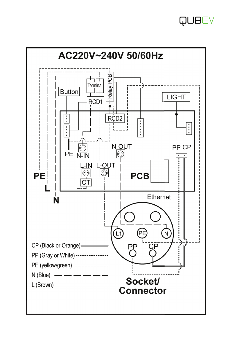
Schematic Diagrams
Figure 6 EVON0090 -1-Phase, Version Schematic Diagram
EARTH IN
ACCORDANCE
WITH CURRENT
REGULATIONS
Installation
QUBEVSM-V01-R0 Installation and Operation Manual Intelligent Electric Vehicle Chargepoints
February 2023 Page 14 of 42
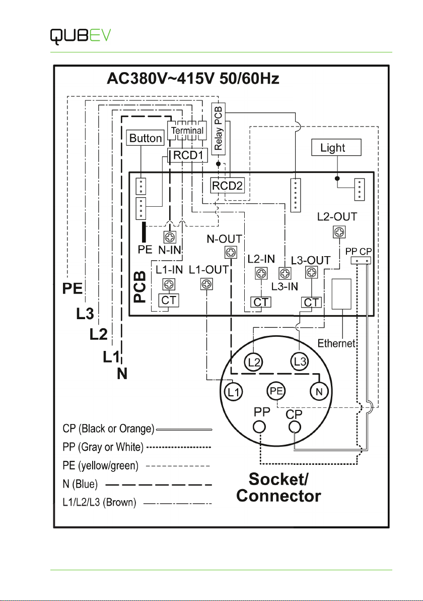
Figure 7 EVON00100 - 3-Phase, Version Schematic Diagram
EARTH IN
ACCORDANCE
WITH CURRENT
REGULATIONS

Installation
Intelligent Electric Vehicle Chargepoints QUBEVSM-V01-R0 Installation and Operation Manual
Page 15 of 42 February 2023
Installation Procedure
NOTE: All electrical work must be performed in accordance with the applicable Electrical Wiring
Regulations for the region of use.
NOTE: If load balancing will be enabled on this charge point it should, ideally, be installed
alongside the ‘standard installation’.
CAUTION: Equipment Damage
During the next steps, the charger front panel will be removed. Take care to not damage or
strain cables or cable connections that may pass between the enclosure and the front panel.
1. Remove the QUBEV Smart from the packaging.
2. Release the fixings that secure the front panel to the rear enclosure.
3. Carefully lift the front panel away from the rear enclosure to access to the interior.
CAUTION: Equipment Damage (Socket Versions)
The front panel is connected to the charger by electrical cables. Take care not to damage,
strain, or disconnect the cables. At the end of the procedure, make sure all connections are
secure before refitting the panel.
4. Visually inspect the QUBEV Smart and internal components.
xAny components that may have come away from the DIN rail in transit must be
refitted to the rail if there is no damage to the component or its securing
mechanism.
IMPORTANT: Items damaged in transit must first be reported to the courier and then
to the supplier.
xWhere possible, photographic evidence of package and/or unit damage
should be provided.
xIncorrect or damaged units must NOT be installed. Contact your supplier to
discuss rectification.
5. Make note of the location of the incoming power terminals within the enclosure. This will
help when positioning the unit to match the customer’s needs.
6. Remove the mounting bracket from the packaging or, if already mounted to the charger,
remove the 4x securing bolts from the bracket then removed the bracket from the charger.
xThe securing bolts will be required when the charger is mounted back onto the
bracket.
NOTE: If the charger will be post mounted, secure the mounting bracket to the plate on the
mounting post using the fasteners provided then move to step 11.
7. Use the mounting bracket to mark the mounting positions.
xPlace the mounting bracket onto the mounting location (wall).
xMake sure the bracket is flat against the wall and is orientated correctly and is level.
xMark the 4 fixing holes onto the surface of the wall.
xIf the power supply cable, CT cable, ethernet cable, etc. will be coming through the
wall, mark the appropriate cable aperture(s).
Installation
QUBEVSM-V01-R0 Installation and Operation Manual Intelligent Electric Vehicle Chargepoints
February 2023 Page 16 of 42
8. Drill the 4x marked fixing holes in the wall and insert the wall plugs.
9. If required, drill the wall for at the cable aperture locations.
10. Secure the mounting bracket to the wall with the 4x screws from the fixing kit.
11. Cut a neat hole in the charger body to allow entry of the power cable and the cable sealing
gland.
xIdeally, the cable should enter the unit from below or through the back of the
enclosure.
xA suitable cable gland must be used to maintain the IP of the unit.
xIf a CT and/or ethernet communications will be used, space may be required for
additional holes and cable glands.
12. Make sure any installation debris is removed from the charger enclosure and the internal
components.
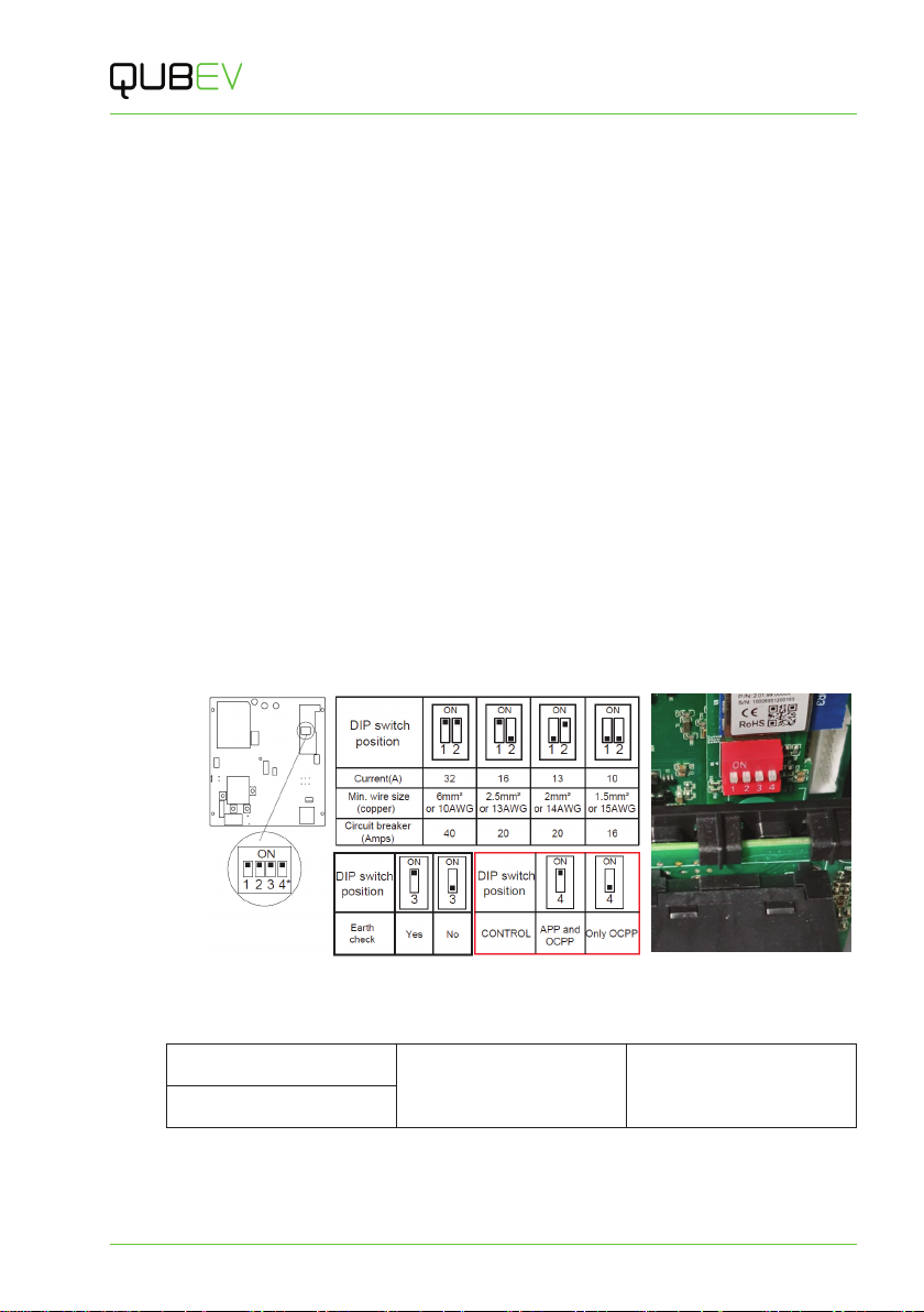
13. If required, adjust the charger output power using the DIP switches.
Factory Default = 32Amps.
xThe DIP switches are located behind the PEN module which may need to be
temporarily removed for access. To gain access…
xremove the securing screw from each end of the DIN rail that holds the PEN
module and the incoming power terminals.
xcarefully lift the DIN and the attached components away.
xSet the DIP switches to the required output as indicated in the illustration below.
Figure 8 DIP Switch Positions
14. Make a record of the Amps setting here.
Amps: Signature: Date:
Name:
15. If required, set the Control method DIP switch to App and OCPP or to Only OCPP, as
shown in the illustration above.
Factory Default = App and OCPP.

Installation
Intelligent Electric Vehicle Chargepoints QUBEVSM-V01-R0 Installation and Operation Manual
Page 17 of 42 February 2023
16. Refit and secure the DIN rail and components.
17. Carefully place the charger body temporarily onto the mounting bracket so that cable
lengths can be determined.
18. Determine the most suitable cable routing and the cable length of all cables that will enter
the enclosure so that each cable can connect to the appropriate terminal(s).
xCable routing may depend on the cable entry point(s) into the enclosure.
19. Terminate the supply cable in the appropriate manner and connect it to the charger as per
the schematic.
x1-phase models will use the terminals L1, N and E (PE).
x3-phase models will use the terminals L1, L2, L3, N and E (PE).
NOTE: The ethernet connection within the charger is solely for connection to an OCPP
back-office. It is not for use with the Smart Application.
20. If required, connect the ethernet cable and the CT cable to the charger.
xIf the supplied rubber gromets will be used, the rubber may need to be carefully cut to
enable the ethernet cable to be fitted.
xThe ethernet connector and the CT connector locations within the enclosure are
shown at Figure 2 on page 7.
xDetails about CT installation are shown on page 19.
21. Make sure ALL accessible cable connections are secure and have not become loose or
damaged in transit or during installation.
22. Make sure ALL debris is removed from the enclosure and that no debris is present on any
of the components.
IMPORTANT NOTE:
It is the responsibility of the installing engineer to make sure that all accessible cable
terminations throughout this product are secure and tight and have not become loose,
strained, or disconnected during transit and/or installation.
NOTE: All electrical work must be performed in accordance with the current Electrical Wiring
Regulations.
CAUTION: Equipment Damage – Sensitive Equipment
If you will be performing insulation resistance tests on the power supply cables, it is advised
to be done BEFORE connecting the cable to the charger. The high voltages applied during
the test may damage sensitive components if tested after the cable is connected.

Installation
QUBEVSM-V01-R0 Installation and Operation Manual Intelligent Electric Vehicle Chargepoints
February 2023 Page 18 of 42
Install Load Balancing
NOTE: This manual assumes the installation of a single chargepoint. Whilst multiple
chargepoints can be connected to a property in a similar way, installers may wish to consider
connecting/monitoring via third-party equipment.
If connecting/monitoring via third-party equipment, make sure you are fully aware of the
manufacturer’s instructions so that the device/system can be installed correctly and in
conjunction with the chargepoint installation.
If load balancing will be enabled on this charge point it should, ideally, be installed alongside the
‘standard installation’.
If installing at a later date, work may be required to enable entry of the Current Transformer (CT)
cable into the chargepoint enclosure.
Overview
Power coming into the property is monitored by a Current Transformer (CT) that clamps around
the property’s incoming power cable and is then connected to the chargepoint.
xThe CT has a cable allowing it to be connected to the chargepoint.
xAdditional cable may be added to the CT cable but to maintain a good signal, it is
recommended that cables extensions are kept as short as possible.
Connect the CT to the Property
Do not use third-party CTs. They may not be compatible with the system and the point at which
load balancing will take place cannot be guaranteed.
1. These instructions are for a single current transformer (CT) used with a 1-phase charger.
Connection of CTs used with a 3-phase charger is very similar and is explained below this
section.
2. The CT clamp should be positioned around the Live (positive) cable between the Meter
and the Consumer Unit.
xThe arrow shown on the CT clamp must point in the direction of electrical flow
TOWARD the consumer unit.
xAlternatively, if required, the CT clamp may be
positioned on the Negative cable leaving the
Consumer Unit. The arrow on the CT clamp must
point in the direction of electrical flow AWAY from
the consumer unit.
3. Release the clip on the CT clamp then open the clamp.
4. Place the CT clamp around the L1 cable.
xMake sure the arrow on the clamp points in the
correct direction.
xNo other cables should pass though the CT clamp.
5. Close the CT clamp and secure it with the clip.
Figure 9 Typical CT Clamp

Installation
Intelligent Electric Vehicle Chargepoints QUBEVSM-V01-R0 Installation and Operation Manual
Page 19 of 42 February 2023
Figure 10 Single-Phase System CT Clamp Positioning Figure 11 three-Phase System CT Clamp Positioning
Connect a 3-Phase CT to the Property
3-Phase electrical supplies have 3x Live cables (L1, L2 & L3).
This means that for a 3-phase system where load balancing is required, a CT clamp must be
installed around each one of L1, L2 and L3.
Unlike a 1-phase system, connecting the CTs to the neutral cable will not allow the system to
function correctly as there are 3 CTs and only 1 Neutral cable.
1. Connect a CT cable clamps to each of L1, L2 and L3 as illustrated above.
Extend the CT Cable
If required, a CT cable may be extended up to a theoretical maximum of 100m.
xTo avoid interference and reduce the loss of signal, extension cables should be as short
as possible. Extensions of 20m or less are recommended.
xExtension cables must be a screened ‘Twisted Pair’. A screened twisted pair within a CAT6
computer network cable may be used.
NOTE: Twisted pairs within a CAT cable are indicated by their matching colours.
Do NOT use conductors of different colours, to extend a cable; interference may be
induced.
If extending more than one CT, use a different colour pair for each CT.
This manual suits for next models
3
Table of contents
Popular Electric Vehicle manuals by other brands

Club Car
Club Car IQ PLUS 2008 Maintenance service supplement

Peterbilt
Peterbilt 220EV 2023 quick start guide

ARCIMOTO
ARCIMOTO FUV 2022 quick start guide

Columbia
Columbia Journeyman Series Maintenance manual

Duck Dynasty
Duck Dynasty DUCK DYNASTY POWER QUAD owner's manual

Ezgo
Ezgo Express L6 ELiTE owner's manual

